Page is loading ...

4001
250mm Chart recorder
Maintenance
Manual
E
UR
O
T
H
E
R
M

Useful Part Numbers
GD236721U080 ...... 80 division chart (35m)
GD236721U100 .... 100 division chart (35m)
GD236721U120 .... 120 division chart (35m)
GD236721U140 .... 140 division chart (35m)
GD236721U150 .... 150 division chart (35m)
LA232380...................... Ink ribbon cartridge
CH050023... 2 Amp Line fuse (110V supply)
CS236673 ... 1 Amp Line fuse (240V supply)
CS237285 ........................ 5A protection fuse
PA239247 ...... Clock support battery (Mk1*)
PA234093 ...... RAM support battery (Mk1*)
PA235482 ................ Support battery (Mk2*)
* Notes:
1 Mk1 refers to the Mark 1 version of the control board.
2 Mk2 refers to the Mark 2 version of the control board.
3 Two off PA235482 required for Mark 2 control board

4001 MAINTENANCE MANUAL
Contents page 1
HA238377
Issue 5A Feb 05
Model 4001
Maintenance Manual
List of Contents
Section Page
1 INTRODUCTION ................................................................................. 1 - 1
1.1 MECHANICAL DESCRIPTION ....................................................................... 1 - 1
1.1.1 Writing and display systems................................................................................ 1 - 1
TRACE PRODUCTION ....................................................................................... 1 - 5
DISPLAY/KEYBOARD......................................................................................... 1 - 5
CHART ILLUMINATION...................................................................................... 1 - 5
1.1.2 Case and card cage........................................................................................... 1 - 6
1.2 Electronics description .................................................................................. 1 - 6
1.2.1 Control board .................................................................................................... 1 - 7
1.2.2 Display/keyboard .............................................................................................. 1 - 7
1.2.3 Card cage ......................................................................................................... 1 - 7
SIGNAL INTERFACE MODULE (SIMS) ................................................................. 1 - 7
INPUT BOARDS ................................................................................................ 1 - 8
RELAY OUTPUT BOARD ..................................................................................... 1 - 8
POWER SUPPLY UNIT (PSU) ............................................................................... 1 - 8
2 PRINCIPLES OF OPERATION ............................................................... 2 - 1
2.1 DC INPUT BOARD ....................................................................................... 2 - 1
2.1.1 Data acquisition ................................................................................................. 2 - 1
2.1.2 Cold junction compensation ................................................................................ 2 - 3
2.1.3 Auto-zero........................................................................................................... 2 - 3
2.1.4 Channel element power supplies.......................................................................... 2 - 3
2.2 RESISTANCE TEMPERATURE DETECTOR (RTD) INPUT BOARD .......................... 2 - 4
2.2.1 Constant current generator .................................................................................. 2 - 4
2.2.2 Input circuitry ..................................................................................................... 2 - 4
2.2.3 Auto zero .......................................................................................................... 2 - 4
2.3 CONTROL BOARD....................................................................................... 2 - 5
2.3.1 Master microprocessor........................................................................................ 2 - 5
2.3.2 Writing system microprocessor ............................................................................ 2 - 5
PRINT HEAD AND RIBBON CARTRIDGE DRIVE................................................... 2 - 5
NEEDLE DRIVE .................................................................................................. 2 - 7
CLUTCH DRIVE ................................................................................................. 2 - 7
CHART DRIVE ................................................................................................... 2 - 7
2.3.3 Display system microprocessor ............................................................................ 2 - 8
KEYBOARDS .................................................................................................... 2 - 8
2.3.4 Other control board functions .............................................................................. 2 - 9
WATCHDOG AND RESET FACILITIES .................................................................. 2 - 9
BATTERY BACK UP SWITCH .............................................................................. 2 - 9
SYSTEM CLOCK ............................................................................................... 2 - 9
EIA232 LINK POWER........................................................................................ 2 - 9
2.3.5 Print head carriage optos.................................................................................... 2 - 10
INITIALISATION ................................................................................................ 2 - 10
RECALIBRATION ............................................................................................... 2 - 11
2.4 DISPLAY BOARD .......................................................................................... 2 - 12
2.4.1 Display.............................................................................................................. 2 - 12
ANODE ADDRESSING ...................................................................................... 2 - 12
2.4.2 Buzzer............................................................................................................... 2 - 12

4001 MAINTENANCE MANUAL
HA2382377
Issue 5A Feb 05Contents page 2
3 PREVENTIVE MAINTENANCE .............................................................. 3 - 1
3.1 EDGE DETECT OPTO ................................................................................... 3 - 1
3.2 DRIVE CORDS .............................................................................................. 3 - 1
3.3 PRINT HEAD POSITIONING.......................................................................... 3 - 1
3.4 CHART DRIVE .............................................................................................. 3 - 1
3.5 SAFETY EARTH CONTINUITY........................................................................ 3 - 1
3.6 CALIBRATION.............................................................................................. 3 - 2
3.6.1 DC input board .................................................................................................. 3 - 2
EQUIPMENT REQUIRED .................................................................................... 3 - 2
CHANNEL CALIBRATION CHECK ...................................................................... 3 - 2
COLD JUNCTION COMPENSATION CHECK ...................................................... 3 - 4
3.6.2 RTD Input board channel calibration check ........................................................... 3 - 4
INTRODUCTION............................................................................................... 3 - 4
FULL CALIBRATION CHECK ............................................................................... 3 - 5
SHORT CHECK................................................................................................. 3 - 5
THREE, FOUR AND FIVE BOARD CHECKS .......................................................... 3 - 7
3.7 TENSIONS AND TORQUES.......................................................................... 3 - 8
3.8 RETURN TO SERVICE CHECKS...................................................................... 3 - 9
List of Contents (Continued
Section Page

4001 MAINTENANCE MANUAL
Contents page 3
HA238377
Issue 5A Feb 05
4 FAULT FINDING GUIDE ....................................................................... 4 - 1
4.1 CONTROL BOARD VERSION........................................................................ 4 - 1
4.1.1 Mark I Control board.......................................................................................... 4 - 2
LINKS .............................................................................................................. 4 - 2
4.1.2 Mark II Control board ......................................................................................... 4 - 3
TEST POINTS .................................................................................................... 4 - 3
4.1.3 Connector pinouts .............................................................................................. 4 - 4
4.2 ERROR/WARNING MESSAGES .................................................................... 4 - 5
4.2.1 Paper misfeed (Edge detector not detecting edge of chart) ..................................... 4 - 5
4.2.2 Cartridge missing (Edge detect opto receives no reflections) ................................... 4 - 5
4.2.3 Servo system failure (No. of steps moved, not = feedback position) ........................ 4 - 6
4.2.4 I/P capabilities exceeded.................................................................................... 4 - 7
4.2.5 Invalid alarm parameter...................................................................................... 4 - 7
4.2.6 Invalid keystroke ................................................................................................ 4 - 7
4.2.7 Replace Link 3 ................................................................................................... 4 - 8
(Mark I Control boards only).......................................................................................... 4 - 8
4.3 WIRING AND CONFIGURATION FAULTS ...................................................... 4 - 8
4.3.1 ?????? Remains at the display after the channel is updated................................... 4 - 8
4.3.2 Channel reading independent of associated input signal ...................................... 4 - 8
4.3.3 RTD board readings become erroneous after time ................................................ 4 - 8
4.3.4 Instrument alarm flashing .................................................................................... 4 - 9
4.3.5 Alarm symbol flashing without an active alarm...................................................... 4 - 9
4.3.6 Alarm will not unassign....................................................................................... 4 - 9
4.3.7 Login number not accepted ................................................................................. 4 - 9
4.3.8 Input data not accepted ...................................................................................... 4 - 9
4.3.9 Communications not operating ............................................................................ 4 - 9
4.4 PRINT QUALITY............................................................................................ 4 - 10
4.4.1 Incorrect colour .................................................................................................. 4 - 10
4.4.3 Poor print Quality............................................................................................... 4 - 11
4.4.4 Reset during printer operation, or during rapid paper transit .................................. 4 - 11
4.4.2 Incorrect print position ........................................................................................ 4 - 11
4.5 PAPER TRANSPORT ...................................................................................... 4 - 12
4.5.2 Incorrect functioning of chart drive ....................................................................... 4 - 12
4.5.1 Chart does not drive ........................................................................................... 4 - 12
4.6 OPERATOR INTERFACE ................................................................................ 4 - 13
4.6.1 No Display ........................................................................................................ 4 - 13
4.6.2 Partial display.................................................................................................... 4 - 14
4.6.3 Display keyboard ............................................................................................... 4 - 14
4.6.4 Ticking display ................................................................................................... 4 - 14
4.7 CONTROL BOARD....................................................................................... 4 - 14
4.7.1 Ticking display ................................................................................................... 4 - 14
4.7.5 No printhead movement at power-on (Mark II control boards only) ........................ 4 - 15
4.7.2 Loss of configuration or user-entered data ............................................................. 4 - 15
4.7.3 Recorder inoperative, but chart illuminated ........................................................... 4 - 15
4.7.4 Display clock not accurate .................................................................................. 4 - 15
4.7.6 Loss of user entered data (Mark II control boards only)........................................... 4 - 16
4.7.7 Configuration not updated (Mark II control boards only) ........................................ 4 - 16
4.7.8 Battery low warning (Mark II control boards only) ................................................. 4 - 16
4.8 MECHANICAL ............................................................................................. 4 - 16
4.8.1 Door difficult to open, close or lock...................................................................... 4 - 16
4.8.2 Access system catch inoperative or stiff ................................................................ 4 - 16
List of Contents (Continued
Section Page

4001 MAINTENANCE MANUAL
HA2382377
Issue 5A Feb 05Contents page 4
5 CORRECTIVE MAINTENANCE .............................................................. 5 - 1
5.1 STATIC ELECTRICITY ..................................................................................... 5 - 1
5.1.1 Introduction........................................................................................................ 5 - 1
TERMINOLOGY ................................................................................................ 5 - 2
5.1.2 Precautions against static discharge ..................................................................... 5 - 3
5.2 PRINT HEAD CARRIAGE ASSEMBLY REMOVAL/REPLACEMENT ....................... 5 - 4
5.2.1 Equipment required ............................................................................................ 5 - 4
5.2.2 Disassembly procedure ....................................................................................... 5 - 4
FEEDBACK STRIP .............................................................................................. 5 - 5
OPTICAL ASSEMBLIES ....................................................................................... 5 - 5
PRINT HEAD..................................................................................................... 5 - 5
5.2.3 Re-assembly procedure ....................................................................................... 5 - 6
PRINT HEAD..................................................................................................... 5 - 6
EDGE DETECTOR AND FEEDBACK STRIP OPTICAL ASSEMBLIES........................... 5 - 6
FEEDBACK STRIP .............................................................................................. 5 - 6
5.2.4 Finishing off ....................................................................................................... 5 - 7
5.3 RIBBON CARTRIDGE CARRIAGE ASSEMBLY REMOVAL / REPLACEMENT ........ 5 - 8
5.3.1 Equipment required ............................................................................................ 5 - 8
5.3.2 Disassembly procedure ........................................................................................ 5 - 8
5.3.3 Replacement of the ribbon cartridge carriage assembly ......................................... 5 - 9
BEVEL GEAR SHIMMING................................................................................... 5 - 9
5.3.4 Re-assembly ....................................................................................................... 5 - 10
5.4 RE-CORDING THE CARRIAGES ..................................................................... 5 - 11
5.4.1 Equipment required ............................................................................................ 5 - 11
LATER INSTRUMENTS........................................................................................ 5 - 11
ORIGINAL DESIGN........................................................................................... 5 - 11
5.4.2 Parts required .................................................................................................... 5 - 11
LATER INSTRUMENTS........................................................................................ 5 - 11
ORIGINAL DESIGN........................................................................................... 5 - 11
5.4.3 PREPARATION.................................................................................................... 5 - 12
5.4.4 Print head carriage re-cording (later recorders) ..................................................... 5 - 12
EXISTING CORD REMOVAL ............................................................................... 5 - 13
NEW CORD INSTALLATION .............................................................................. 5 - 13
RE-ASSEMBLY ................................................................................................... 5 - 14
5.4.5 Ribbon cartridge re-cording (later recorders) ......................................................... 5 - 15
EXISTING CORD REMOVAL ............................................................................... 5 - 16
NEW CORD INSTALLATION .............................................................................. 5 - 17
RE-ASSEMBLY ................................................................................................... 5 - 18
5.4.6 Print head carriage re-cording (Original design) ................................................... 5 - 19
PREPARATION .................................................................................................. 5 - 19
EXISTING CORD REMOVAL ............................................................................... 5 - 19
NEW CORD INSTALLATION .............................................................................. 5 - 20
5.4.7 Ribbon Cartridge Carriage re-cording (Original design) ........................................ 5 - 22
EXISTING CORD REMOVAL ............................................................................... 5 - 22
NEW CORD INSTALLATION .............................................................................. 5 - 23
5.4.8 Cord tension checks (original design) ................................................................... 5 - 24
RIBBON CARTRIDGE CARRIAGE ........................................................................ 5 - 24
PRINT HEAD CARRIAGE ASSEMBLY ................................................................... 5 - 24
5.4.9 Colour select setting up procedure ....................................................................... 5 - 25
PRINT NEEDLES TOO MUCH TO THE LEFT.......................................................... 5 - 25
PRINT NEEDLES TOO MUCH TO THE LEFT.......................................................... 5 - 25
5.4.10 Re-assembly ..................................................................................................... 5 - 26
5.5 SETTING UP THE OPTICAL ASSEMBLIES ........................................................ 5 - 27
5.5.1 Original design.................................................................................................. 5 - 27
EQUIPMENT REQUIRED .................................................................................... 5 - 27
EDGE DETECTOR.............................................................................................. 5 - 27
FEEDBACK STRIP .............................................................................................. 5 - 28
5.5.2 Current design ................................................................................................... 5 - 28
List of Contents (Continued
Section Page

4001 MAINTENANCE MANUAL
Contents page 5
HA238377
Issue 5A Feb 05
5.6 SERVO / COLOUR SELECT MOTOR REPLACEMENT ....................................... 5 - 29
5.6.1 Equipment required ............................................................................................ 5 - 29
5.6.2 Removal ............................................................................................................ 5 - 29
5.6.3 Replacement ...................................................................................................... 5 - 29
5.7 CHART DRIVE MAINTENANCE ..................................................................... 5 - 30
5.7.1 Equipment required ............................................................................................ 5 - 30
5.7.2 Disassembly procedure ....................................................................................... 5 - 30
CHART DRIVE MOTOR ...................................................................................... 5 - 31
TAKE-UP SPOOL................................................................................................ 5 - 31
CHART DRIVE GEARHEAD................................................................................. 5 - 31
DRIVE SHAFT, CHART GUIDE AND TOOTHED BELT ............................................. 5 - 31
5.7.3 Re-assembly procedure ....................................................................................... 5 - 32
DRIVE SHAFT AND CHART GUIDE ..................................................................... 5 - 32
CHART DRIVE GEARHEAD/MOTOR ................................................................... 5 - 32
TOOTHED BELT................................................................................................. 5 - 32
TAKE-UP SPOOL................................................................................................ 5 - 32
5.7.4 Finishing off ....................................................................................................... 5 - 33
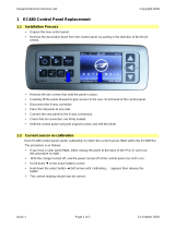
5.8 CHART CONTROL PANEL REPLACEMENT ...................................................... 5 - 34
5.8.1 Equipment required ............................................................................................ 5 - 34
5.8.2 Removal procedure............................................................................................. 5 - 34
5.8.3 Replacement procedure....................................................................................... 5 - 35
5.8.4 Finishing off ....................................................................................................... 5 - 36
5.9 KEYBOARD, DISPLAY AND CHART ILLUMINATION ASSEMBLY REPLACEMENT.. 5 - 37
5.9.1 Equipment required ............................................................................................ 5 - 37
5.9.2 Keyboard panel and chart illumination assembly removal ...................................... 5 - 37
CHART ILLUMINATION ASSEMBLY REPLACEMENT .............................................. 5 - 37
PROCEDURE..................................................................................................... 5 - 37
5.9.3 Removal of the keyboard and the display board ................................................... 5 - 38
5.9.4 Re-assembly procedure ....................................................................................... 5 - 39
DISPLAY BOARD ............................................................................................... 5 - 39
RIBBON CARTRIDGE CARRIAGE ASSEMBLY ....................................................... 5 - 39
KEYBOARD ...................................................................................................... 5 - 39
5.9.5 Finishing off ....................................................................................................... 5 - 40
5.10 RECORDER CASE ...................................................................................... 5 - 40
5.10.1 Introduction ..................................................................................................... 5 - 41
5.10.2 Equipment required .......................................................................................... 5 - 41
5.10.3 Parts required .................................................................................................. 5 - 41
5.10.4 Top cover replacement ...................................................................................... 5 - 41
5.10.5 Lower cover replacement .................................................................................. 5 - 42
PANEL MOUNTING CASE................................................................................. 5 - 42
PORTABLE CASE ............................................................................................... 5 - 42
5.10.6 Case conversion............................................................................................... 5 - 43
PANEL MOUNTING TO PORTABLE ..................................................................... 5 - 43
PORTABLE TO PANEL MOUNTING ..................................................................... 5 - 43
5.10.7 Mother board replacement ................................................................................ 5 - 44
EQUIPMENT REQUIRED .................................................................................... 5 - 44
MOTHER BOARD REMOVAL .............................................................................. 5 - 44
REPLACEMENT MOTHER BOARD INSTALLATION ................................................ 5 - 45
5.11 DOOR AND ACCESS SYSTEM CATCH REPLACEMENT .................................. 5 - 46
5.11.1 Door replacement............................................................................................. 5 - 46
DOOR CATCH EASING .................................................................................... 5 - 46
5.11.2 Latch Spring Replacement ................................................................................. 5 - 46
5.11.3 Door lock replacement ...................................................................................... 5 - 46
5.11.4 Access system catch replacement ....................................................................... 5 - 47
EQUIPMENT REQUIRED .................................................................................... 5 - 47
REMOVAL PROCEDURE ..................................................................................... 5 - 47
REPLACEMENT PROCEDURE.............................................................................. 5 - 47
List of Contents (Continued
Section Page

4001 MAINTENANCE MANUAL
HA2382377
Issue 5A Feb 05Contents page 6
5.12 RECORDER STATIC GROUNDING CONTINUITY .......................................... 5 - 49
5.12.1 Introduction ..................................................................................................... 5 - 49
5.12.2 Equipment required .......................................................................................... 5 - 49
5.12.3 Continuity check............................................................................................... 5 - 52
5.13 BATTERY REPLACEMENT............................................................................. 5 - 57
5.13.1 RAM back-up battery replacement ..................................................................... 5 - 57
WITH POWER ON............................................................................................ 5 - 57
WITH POWER OFF ........................................................................................... 5 - 57
5.13.2 Clock support battery ....................................................................................... 5 - 58
5.13.3 Battery disposal ............................................................................................... 5 - 58
5.14 DISPLAY BOARD MODIFICATION FOR 5V CHART ILLUMINATION ................. 5 - 59
5.14.1 Display board version....................................................................................... 5 - 59
5.14.2 Modification procedures ................................................................................... 5 - 60
GENERAL......................................................................................................... 5 - 60
PROCEDURE A ................................................................................................ 5 - 61
PROCEDURE B.................................................................................................. 5 - 62
PROCEDURE C ................................................................................................. 5 - 62
5.15 DISPLAY SIDEPLATE REPLACEMENT ............................................................. 5 - 63
5.15.1 Introduction ..................................................................................................... 5 - 63
5.15.2 Kit contents ...................................................................................................... 5 - 63
5.15.3 Equipment required .......................................................................................... 5 - 63
5.15.4 Disassembly procedure ..................................................................................... 5 - 64
5.15.5 SUPPORT PLATE PULLEYS .................................................................................. 5 - 66
FITTING THE BRACKETS .................................................................................... 5 - 66
FITTING THE PULLEYS........................................................................................ 5 - 66
5.15.6 Reassembly procedure ...................................................................................... 5 - 67
6 ELECTRONICS..................................................................................... 6 - 1
6.1 DC Input board............................................................................................ 6 - 3
6.1.1 DC input board component layout ....................................................................... 6 - 3
6.1.2 Schematic disagram ........................................................................................... 6 - 5
6.2 RTD Input board........................................................................................... 6 - 9
6.2.1 RTD input board component layout....................................................................... 6 - 9
6.2.2 RTD Input board schematic diagram..................................................................... 6 - 11
6.3 CONTROL BOARD....................................................................................... 6 - 15
6.3.1 Setting the low voltage threshold.......................................................................... 6 - 15
EQUIPMENT REQUIRED .................................................................................... 6 - 15
PROCEDURE..................................................................................................... 6 - 15
6.3.2 Mark I Control board layout ................................................................................ 6 - 17
6.3.3 Mark I Control board schematic diagram ............................................................. 6 - 19
6.4 PSU BOARD ................................................................................................ 6 - 27
6.4.1 PSU Board component layout .............................................................................. 6 - 27
6.4.2 PSU Board schematic diagram............................................................................. 6 - 29
6.5 MOTHER BOARD......................................................................................... 6 - 33
6.5.1 Mother board schematic diagram ........................................................................ 6 - 33
6.6 RELAY OUTPUT BOARD ................................................................................ 6 - 35
6.6.1 Relay output board component layout .................................................................. 6 - 35
6.6.2 Relay output board schematic diagram................................................................. 6 - 37
6.7 DISPLAY BOARD .......................................................................................... 6 - 39
6.7.1 Display board component layout ......................................................................... 6 - 39
6.7.2 Display board schematic diagram........................................................................ 6 - 41
6.8 EIA232 TO EIA422 CONVERSION MODULE................................................. 6 - 43
6.8.1 Conversion module component layout .................................................................. 6 - 43
6.8.2 Conversion module schematic diagram ................................................................ 6 - 43
6.9 MARK II CONTROL BOARD .......................................................................... 6 - 45
6.9.1 Mark II Control board layout ............................................................................... 6 - 45
6.9.2 Mark II Control board schematic diagram............................................................. 6 - 47
List of Contents (Continued
Section Page

4001 MAINTENANCE MANUAL
Contents page 7
HA238377
Issue 5A Feb 05
7 SPARE PARTS ..................................................................................... 7 - 1
7.1 CONSUMABLES .......................................................................................... 7 - 1
7.2 ACCESSORIES............................................................................................. 7 - 1
7.3 CASE ASSEMBLY ......................................................................................... 7 - 1
7.4 POWER SUPPLY ........................................................................................... 7 - 1
7.5 INPUT/OUTPUT (I/O) BOARDS..................................................................... 7 - 1
7.5.1 Two-wire dc input ............................................................................................... 7 - 1
7.5.2 Resistance thermometer input ............................................................................... 7 - 1
7.5.3 Relay output....................................................................................................... 7 - 1
7.6 CONTROL BOARD....................................................................................... 7 - 1
7.6.1 Mark I ............................................................................................................... 7 - 1
7.6.2 Mark II .............................................................................................................. 7 - 1
7.7 DISPLAY ASSEMBLY...................................................................................... 7 - 2
7.8 WRITING SYSTEM ....................................................................................... 7 - 2
7.8 DATAPACK CLEANING SOFTWARE............................................................... 7 - 2
7.9 OPTION UP-GRADE KITS .............................................................................. 7 - 2
7.10 SERVICE ACCESSORIES ............................................................................. 7 - 2
7.11 CONFIGURATION EQUIPMENT.................................................................. 7 - 2
7.12 LITERATURE ............................................................................................... 7 - 2
7.13 SOFTWARE ROM PACKS............................................................................ 7 - 2
7.14 SPARE PART IDENTIFICATION ..................................................................... 7 - 3
7.14.1 Electronics ....................................................................................................... 7 - 4
7.14.2 Writing system ................................................................................................. 7 - 5
OVERVIEW ...................................................................................................... 7 - 5
8 PARTS LISTS....................................................................................... 8 - 1
8.1 INTRODUCTION.......................................................................................... 8 - 1
8.1.1 Column headings ............................................................................................... 8 - 1
ITEM ................................................................................................................ 8 - 1
PART NUMBER.................................................................................................. 8 - 1
NO USED ........................................................................................................ 8 - 1
DESCRIPTION................................................................................................... 8 - 1
COMMENTS .................................................................................................... 8 - 1
8.2 CASE.......................................................................................................... 8 - 2
8.3 DISPLAY SYSTEM ASSEMBLY......................................................................... 8 - 6
8.4 WRITING SYSTEM ASSEMBLY....................................................................... 8 - 9
8.5 CHART DRIVE SYSTEM ................................................................................. 8 - 16
Index ............................................................................................ Index - 1
List of Contents (Continued
Section Page

4001 MAINTENANCE MANUAL
HA2382377
Issue 5A Feb 05Contents page 8
This page is deliberately left blank

4001 MAINTENANCE MANUAL
HA238377
Issue 5A Feb 05
Section 1
Page 1 - 1
1 INTRODUCTION
This manual is intended for use by maintenance personnel when servicing and maintaining the 4001 recorder. It is
assumed that those using this manual are familiar with the Installation and Operation Manual supplied with the re-
corder.
The manual is divided into a number of sections, as follows:
1. Introduction. This gives a brief introduction to the manual and to the recorder.
2. Principles of operation. This section describes how input data is accessed and processed, and how the control
board operates on the resulting signal to provide traces on the chart, alarm outputs etc. Also described are com-
munications between the control board and the display and keyboards.
3. Preventive maintenance. This section contains details of the periodic checks which may be made in order to en-
sure trouble-free operation. Included in this section is a procedure for checking the calibration of input boards.
4. Fault diagnosis. Section 4 is a basic fault-finding guide, intended to be used in locating faulty any area of the
recorder.
5. Corrective Maintenance. Section 5 provides disassembly, re-assembly and replacement procedures for the me-
chanical assemblies which make up the recorder.
6. Electronic Subsystems. This section contains circuit board schematics and layouts for the printed circuit boards
used in the 4001 recorder.
7. Spare Parts. This gives a list of those spare parts which are available for the 4001 recorder.
8. Parts lists. A complete list of parts for the recorder.
Note: As the recorder has been obsolete for some years, most spare parts are no longer available.
1.1 MECHANICAL DESCRIPTION
Mechanically, the recorder is in two parts:
1. Writing and display systems
2. Case and card cage
1.1.1 Writing and display systems
Figures 1.1.1 a, b and c show the major functional elements of the writing system.
The writing system mechanical assembly is located on guide rails secured to the inner sides of the case. With the case
door open, the writing system may be pulled forwards on the rails, until it is arrested by safety stops. To change chart
or ribbon cartridge, or to gain access to certain of the mechanical sub-assemblies, the top part of the writing system
may be opened upwards, about a horizontal hinge system. To gain access to the major electronics sub-systems, the
writing system may be swung open on a vertical hinge.
The writing system contains two stepper motors, one to drive the chart; the other to drive the print head and ribbon
cartridge assemblies. Under normal recording conditions, chart speed is as defined by the customer configuration,
entered via the display/keyboard (see Installation and Operation manual). Fast forward and rewind facilities are also
available, and are controlled via the Chart Control panel located to the bottom right of the chart. In order to carry out
a fast forward or rewind operation, the print function has first to be disabled by the use of an On/Off line key, also
located on the chart control panel.
Full operating procedures are given in the Installation and Operation manual supplied with the recorder.

4001 MAINTENANCE MANUAL
Section 1
Page 1 - 2
HA238377
Issue 5A Feb 05
Keyboard/display
assembly
Tear-off cord tensioning-
spring anchor point
Chart illumination
assembly
Keyboard/display har-
ness retaining bracket
Inner chassis liner
Front plate
Chart control panel
Tear-off cord handle
On-off switch
Chart drive
access cover
Pinch roller
Print head carriage
Upper chart guide
Print ribbon cartridge
retaining clip
1.1.1 WRITING AND DISPLAY SYSTEMS (Cont.)
Figure 1.1.1a Writing system front view

4001 MAINTENANCE MANUAL
HA238377
Issue 5A Feb 05
Section 1
Page 1 - 3
Opto flexi
earthing point
Opto flexi
earthing point
Upper chart
guide
Ribbon cartridge carriage
guide-rail support-plate
Opto and print
head flexies
Roll chart
pay-off spool
Ribbon drive
gearbox
Printhead
carriage
Display board
Ribbon cartridge carriage
guide-rail
1.1.1 WRITING AND DISPLAY SYSTEMS (Cont.)
Figure 1.1.1b Writing system top view

4001 MAINTENANCE MANUAL
Section 1
Page 1 - 4
HA238377
Issue 5A Feb 05
Servo/Colour
select motor
Ribbon cartridge carriage
drive capstan
Print head carriage
drive capstan
Chart drive motor
Chassis support bracket
Chart drive
gearbox
Chart drive shaft
Chart tear-off cord
tension spring
Lower chart guide
Take-up spool
1.1.1 WRITING AND DISPLAY SYSTEMS (Cont.)
Figure 1.1.1c Writing system view on underside

4001 MAINTENANCE MANUAL
HA238377
Issue 5A Feb 05
Section 1
Page 1 - 5
1 Red
2 Orange
3 Green
4 Violet
5 Blue
6 Black
7 Red
8 Orange
9 Green
10 Violet
11 Blue
12 Black
13 Red
14 Orange
15 Green
16 Violet
17 Blue
18 Black
19 Red
20 Orange
21 Green
22 Violet
23 Blue
24 Black
25 red
26 Orange
27 Green
28 Violet
29 Blue
30 Black
Chan-
nel
Colour
Chan-
nel
Colour
Chan-
nel
Colour
1.1.1 WRITING AND DISPLAY SYSTEMS (Cont.)
TRACE PRODUCTION
Traces are produced on the chart by a nine-needle print head (carried on a guide rail behind the chart) in conjunction
with a six-colour continuous ribbon held in a cartridge. This cartridge is clipped to a carriage carried on a second
guide rail, above the chart.
The print head carries nine needles arranged in a vertical line. The number of needles used depends on chart speed.
At high chart speeds all nine needles are used, with the position for each of the nine dots being calculated separately.
The number of needles used at any particular chart speed is detailed in the Installation and Operation manual, supplied
with the recorder.
The ribbon is advanced by means of a mechanical gearbox, driven by a rack associated with the ribbon cartridge car-
riage guide rail. Each of the 30 input channels is allocated one of the six colours, as shown in table 1.1.1. The colour-
select system prints all the traces for colour 1 first, followed by those for colour 2 and so on. (The colour sequence is
that of the ribbon viz: red, orange, green, violet, blue, black.)
When an instruction to print a dot is received, the correct colour for the dot is selected by moving the ribbon cartridge
relative to the print head. The print head and cartridge carriages are now moved to the correct position for the dot,
and the relevant needle is energised by means of an associated solenoid, The needle strikes the under side of the
chart, such that the area of chart above the needle is forced into contact with the ribbon, producing a coloured dot.
The correct position for the dot is determined by optical means, using the edge of the chart as a datum, and a feedback
grating strip, located on the rear of the print head carriage guide rail, to determine the precise position of the print
head.
Table 1.1.1 Channel colour allocation
DISPLAY/KEYBOARD
This assembly consists of a sealed, membrane keyboard mounted on the writing system chassis above the chart. The
eighty-character vacuum fluorescent display unit is mounted on a printed circuit board (Display board AH232100),
located behind the keyboard assembly.
The keyboard is used to enter or to alter the instrument’s configuration. The display shows either the measured values
of channels, or the ‘pages’ used during configuration (see the Installation and Operation manual).
CHART ILLUMINATION
Chart illumination is by means of a chart illumination assembly containing a number of low-voltage lamps. The as-
sembly is located below the display/keyboard, and is accessed by removing the keyboard.

4001 MAINTENANCE MANUAL
Section 1
Page 1 - 6
HA238377
Issue 5A Feb 05
EIA232
outlet
EIA232 to
EIA422
conversion
module
(option)
I/O Board
SIM
I/O Board
SIM
I/O Board
SIM
DART
Watchdog.
Battery back-up
Real-time clock
RAM
Master
microprocessor
and memory
Keyboard
display
Display driver
Print head
solenoids
Needle driver
Servo/
Colour select
motor
Motor driver
Writing system
microprocessor
Chart drive
motor
Motor driver
Opto detectors
DATA
ADDRESS
CONTROL BOARD
WRITING SYSTEM
CUSTOMER CONNECTIONS
CARD CAGE
Display
microprocessor
1.1.2 Case and card cage
The recorder case houses the writing and display systems, and a printed-circuit card-cage. The card cage holds the
Power Supply Unit (PSU) and the input/output (I/O) circuit boards. Signal Interface Modules (SIMs), which allow
the connection of customer equipments to be made to the recorder, are clipped to the rear of the card cage.
The PSU and I/O boards are all plugged into a backplane (mother board) by means of which the control board com-
municates with the I/O boards. A second connector on each I/O board mates with a matching connector mounted on
an associated SIM, accessible by removing the rear (terminal) cover of the instrument. SIMs associated with DC
input boards also contain a temperature sensor which is used to provide cold junction compensation (CJC).
1.2 ELECTRONICS DESCRIPTION
Figure 1.2 is an overall block diagram of the recorder electronics systems.
Figure 1.2 4001 Block diagram

4001 MAINTENANCE MANUAL
HA238377
Issue 5A Feb 05
Section 1
Page 1 - 7
1.2 ELECTRONICS DESCRIPTION (Cont.)
The recorder receives voltage or current signals from external transducers (thermocouples, resistance thermometers,
pressure transducers etc.) and scales and linearises them, as programmed via the keyboard. After processing, the re-
sulting data is used to produce traces on the chart, to display the measured value ant to generate alarm signals as re-
quired.
The recorder carries out a self-checking routine and produces error and/or warning messages if, for example, the chart
is missing or if there is a fault in the drive mechanism for he print head etc.
The electronics sub-systems are located in three areas of the recorder:
a. The control board
b. The Display/keyboard assembly
c. The card cage
1.2.1 Control board
The control board contains three microprocessors and associated circuitry to control the operation of the recorder.
The microprocessors are arranged as a master and two slaves. The master microprocessor controls the slave micro-
processors and is also responsible for communicating with the I/O boards and for supporting external communica-
tions, if the EIA232/EIA422 serial data link is installed.
One of the slave processors is used to control the writing system (chart drive, print head/ribbon cartridge, print nee-
dles etc.). The other slave is used to control the display and to poll the keyboards. (Reading the keyboards is done by
the master processor - see section 2.3.3.
1.2.2 Display/keyboard
Writing to the display is performed using two data streams: anode data and grid data. Thee data is sent from the dis-
play slave microprocessor as a serial data stream to latch/driver ICs on the display board. The anode data consists of
72 bits, sufficient to drive one vertical pair of characters. The grid data consists of 40 bits, only one of which is ‘on’
at any one time.
Data from the display keyboard and the chart control panel is polled by the slave microprocessor, which pulls each of
the polling lines high, in turn. This results in one of the data lines going high, should one of the keys happen to be
pressed at that time. The data lines are read by the master microprocessor.
1.2.3 Card cage
The card cage is an integral part of the recorder case, and holds the PSU and the I/O boards with their associated Sig-
nal Interface Modules (SIMs). Each I/O board is fitted with two connectors - one of which connects with the mother
boards; the other with the SIM.
SIGNAL INTERFACE MODULE (SIMS)
The SIM is the means by which (non-comms) signals enter and leave the recorder.
Input boards have six channels and the SIM provides the means of terminating customer pinouts from thermocouples,
RTDs or other suitable transducer type.
Relay output boards provide the necessary drive signals to relays located in either of the two types of Relay Output
SIM. One type of Relay Output SIM contains four high power relays; the other contains eight medium power relays.

4001 MAINTENANCE MANUAL
Section 1
Page 1 - 8
HA238377
Issue 5A Feb 05
1.2.3 CARD CAGE (Cont.)
INPUT BOARDS
The input boards accept up to six inputs via the relevant type of SIM. The channels are isolated from one another and
from the remainder of the input board circuitry by means of independent transformer secondaries for each channel.
The gain, scaling and linearisation applied to the input signals are determined by a slave processor on the input board,
under the control of the control board master microprocessor.
For each channel, an analogue-to-digital converter (ADC) is used to produce a digital value for the input signal. This
value is applied to a number of look-up tables to produce a scaled and linearised version of the input signal. This is
output serially to the control board master microprocessor once a second.
RELAY OUTPUT BOARD
The relay output board contains a slave processor under the control of the control board master microprocessor. The
outputs from this slave are passed via a latch to relay drivers, which drive the relays located in the SIM.
The relay coils are energised for power on and non alarm conditions. Thus, if power fails, the relays go into there
alarm state.
The recorder allows a maximum of 60 alarm set-points to be allocated freely amongst the 30 possible input channels.
In other words, the relay outputs can each be activated by any of the 60 set points.
Relay configuration is ‘Form C’.
POWER SUPPLY UNIT (PSU)
WARNING!
WITH LINE POWER APPLIED, LARGE AREAS OF THE CIRCUIT BOARD WITHIN THE PSU ARE AT
A HIGH VOLTAGE. THIS PRESENTS A HAZARD TO THE USER IF THE CARD IS EXPOSED.
DC power for the recorder electronics is generated by a switched-mode PSU located in the card cage. This PSU sup-
plies two voltage rails: 24 Volts and 5 Volts.
Power for the serial communications link is generated on the control board from the 24 Volt rail.
The power to drive the vacuum fluorescent display is generated on the display board.
Input channel power is generated on each input board from the 24 Volt rail.

4001 MAINTENANCE MANUAL
HA238377
Issue 5A Feb 05
Section 2
Page 2 - 1
2 PRINCIPLES OF OPERATION
The operation of the recorder is under the control of the control board located at the rear of the writing system. The
control board contains three microprocessors set up as a master and two slaves. The software to run the recorder is
held in a pair of Programmable, read Only Memories (PROMS). The customer entered configuration data (held in a
battery-backed Random Access Memory (RAM)) provides the master processor with the information necessary to
process the input signals as appropriate.
The input/output (I/O), external communications (if implemented) and the Real Time Clock (RTC) functions are all
controlled directly by the master processor. The writing system is controlled by one of the slaves; the display and
keyboard are under the control of the other.
The writing system slave outputs data which is used to energise the chart drive motor, the print head/ribbon carriage
motor and to actuate the print head needles.
The display system slave is responsible for providing anode and grid data to the display, and for polling the display
and chart-control keyboards.
Each I/O board is located in a slot in the card cage. Each slot has a unique address which is permanently set up on the
mother board. Thus, providing that the correct board type for each slot is entered during the configuration of the re-
corder, any I/O board can be placed in any slot. It should be noted, however, that for proper operation of the recorder,
slot one may not have an output board fitted.
2.1 DC INPUT BOARD
Figure 2.1 is a block diagram for the dc input board.
2.1.1 Data acquisition
The input signal (from a transducer) is filtered by a two-pole RC circuit before being routed to an analogue-to-digital
converter (ADC) (IC2; IC4) via an attenuation/amplification select circuit (IC1, IC2, IC3). The gain or attenuation
selected depends on the customer-entered configuration, and is passed to the input board microprocessor at initialisa-
tion, and whenever the configuration is edited.
The output of the ADC is a bit stream in which the proportion of logic 1s represents the amplitude of the input signal.
The signal is compressed by counting the number of zeros in a given number of ADC clock pulses, the output of the
counter then being transmitted serially across a Galvanic isolation barrier, consisting of an opto-isolator (IC5; IC6).
The ADC and data compression functions are implemented using a gate array (IC4) which additionally controls the
communication of attenuation/gain information to the relevant channel elements.
The dc input board contains six identical channel circuits as described above.
The timing of the transmissions across the barrier is such that adjacent channels’ data do not appear at the outputs of
their opto-isolators at the same time. This allows the outputs of channels 1 and 2, of channels 3 and 4 and of channels
5 and 6 to be wired together in pairs. The three resulting data streams are reconstructed by voltage comparators
(IC16) before being presented to three serial input registers (IC13, IC14 and IC15) - one for each pair of channels.
The data in the registers is read, one channel at a time, and presented to a number of look-up tables held in RAM. The
tables apply offset, scale and linearisation to the data stream. The offset table contents are calculated from auto zero
and cold junction compensation inputs.

4001 MAINTENANCE MANUAL
Section 2
Page 2 - 2
HA238377
Issue 5A Feb 05
Channel 1
Channel 6
Primary
-6
+14
-6
+14
Smoothing
& Regulation
Smoothing
& Regulation
Control
Counter
CPU Clock
Attenuation;
Gain;
Auto zero
ADC
Gate array (channel 1)
Pulse
shaping
Attenuation;
Gain;
Auto zero
ADC
Gate array (channel 2)
Isolation
barrier
Control
Control
Isolation
barrier
Isolation
barrier
Isolation
barrier
Register
Register
Register
Control
Control
Ch1/2
Ch3/4
Ch5/6
PIA Port A
PIA Port A
Control
Control
Control
PIA Port B
0 to 6
Port B
Control
Offset
lookup
table
Linearising
lookup
table
Digital
Filter
RAM
Control
DataData
Module Listen
Module Talk
CJC Data
Control
(CPU)
Wake-up
Mode control
Mode control
Data com-
pression &
control logic
Data com-
pression &
control logic
Input
Input
Input
(cold junction)
ADC
SIM
Control Board
D0 to D7
PIA
2.1.1 DATA ACQUISITION (Cont.)
Figure 2.1 DC input board - block diagram
/