Page is loading ...

pH
CONTROLLER/MONITO
R
Model : PPH-2108
Your purchase of this pH CONTROLLER/MONITO
R
MONITOR marks a step forward for you into the field of
precision measurement. Althou
g
h this pH controller is a
complex and delicate instrument, its durable structure
developed. Please read the followin
g
instructions carefully
and always keep this manual within easy reach.
OPERATION MANUAL

Caution Symbol
Caution :
* Risk of electric shock !
Caution :
* Do not use fingers or any tool
to touch the FLASH TUBE.
* The instrument contains no user
serviceable parts and should not
be opened by the user.
* Repair or after service should be
done by a qualified technician
only.
* Power plug should apply the correct
ACV power voltage
* Operating duty cycle should be
adhered to.
* Cleaning - Only use the dry cloth to
clean the plastic case !
* Equipment protectted throughout
by Double Insulation or Reinforced
Insulation.
Environmental Condition
* Comply with EN61010.
Transient overvoltage at Mains Supply 2500V.
* Pollution Degree 2.
* Altitude up to 2000 meters.
* Indoor use.
* Relative humidity 80% max.

TABLE OF CONTENTS
1. FEATURES......................................................................
.
1
2. SPECIFICATIONS.............................................................2
2-1 General Specifications................................................ 2
2-2 Electrical Specifications..............................................
.
4
3. FRONT PANEL DESCRIPTION...........................................
.
5
3-1 Display.....................................................................
.
5
3-2 PV ( process value ) indicator..................................... 5
3-3 SV ( set value ) indicator............................................5
3-4 Set Button................................................................
.
5
3-5 Button..................................................................▼ 5
3-6 Button..................................................................▲ 5
3-7 PH/Temp Button........................................................5
3-8 pH control relay indicator...........................................
.
5
3-9 Temp. control relay indicator...................................... 5
3-10 pH indicator............................................................
.
5
3-11 Temp. indicator.......................................................
.
5
3-12 Wire terminals ........................................................ 5
3-13 RS232 terminal........................................................5
3-14 BNC Input socket ....................................................5
3-15 Case holder ............................................................ 5
3-16 pH Electrode plug ( optional )................................... 5
3-17 pH Electrode ( optional )..........................................
.
5
3-18 Temp. Probe ( optional )..........................................
.
5
3-19 Temp. Wires ( optional )..........................................
.
5
4. MEASURING PROCEDURE................................................
.
5
4-1 Terminal connection..................................................
.
6
4-2 pH calibration ...........................................................6
4-3 pH measurement ( with ATC probe )...........................7
4-4 pH measurement ( without ATC probe )...................... 7
4-5 1st layer setting procedures.......................................
.
8
4-6 2nd layer setting procedures......................................
.
10
5. pH CALIBRATION PROCEDURES.......................................14
6. RS232 PC SERIAL INTERFACE..........................................17
7. pH ELECTRODE QUALITY CHECK.....................................
.
19
8. SYSTEM RESET............................................................... 19
9. THE ADDRESS OF AFTER SERVICE CENTER...................... 20

1. FEATURES
* Professional pH and Temp. measurement monitor and
controller.
* pH range : 0 to 14 pH x 0.01 pH.
* pH function with high input impedance avoids measuring
error.
* Optional Temp. probe ( ATC probe, Automatic Temp.
Compensation probe ) is available for pH measurement
compensation and the Temp. measurement.
* Wide manual temperature compensation for pH function,
adjustment can be easily operated by push button on
the front panel.
* pH calibration is easily to be done by push button on the
front panel.
* Build in pH control relay and the Temp. control relay.
* Relay will be make action ( On/Off ) when the reading
value reach high limit or low limit value.
* Temperature Offset value setting.
* Hysteresis value setting for high and low alarm.
* , temp. unit setting with default.℃℉
* Large red LED display, high brightness and easy to read.
* RS232 computer interface, send out the pH and the
temperature data at the same time.
* Optional pH electrode.
* Optional Temperature probe ( ATC probe ).
* Optional data acquisition software.
* Optional GSM controller.
* Microprocessor circuit ensures high accuracy and
provides special functions and features.
* Standard 96 X 48 mm DIN case.
* Wide applications: water conditioning, aquariums,
beverage, fish hatcheries, food processing,
photography, laboratory, paper industry, plating
industry, quality control, school & college.
1

2. SPECIFICATIONS
2-1 General Specifications
Display 4 digits red LED, digit size : 14 mm.
Circuit Custom chip of microprocessor LSI
circuit.
Range PH 0 to 14 PH
Temp. -30 to 100 ℃
Display Unit pH pH
Temp. , ℃℉
pH Input 10^12 ohm
Impedance
Temperature Manual -30 to 100 , be adjusted by℃
Compensation push button on front panel.
for pH Automatic With the optional Temp.
measurement ( ATC ) probe ( TP-07A )
0 to 65 .℃
pH PH7, PH4, and PH10, 3 points calibration
Calibration ensure the best linearity and accuracy.
pH Optional,
Electrode Any PH electrode with BNC connector.
Temp. Probe Optional, 0 to 65 , TP-07A℃
ATC Probe
Probe Calibration Can set the meter's total operation period to
Period Setting warn the user to make the new calibration for
* PCPS function
the pH electrode.
Sampling Time Approx. 1 second.
Relay outputs Number 2 relays
Function
Relay 1 :
pH control relay.
Relay 2 :
Temperature control relay.
Max load 1 ACA/250 ACV
1 DCA/24 DCV
2

Setting value 1. High limit value setting.
2. Low limit value setting.
3. Hysteresis value setting.
4. Temp. Offset value setting.
* 1, 2, 3 Setting for pH and Temp. function.
External DC 12 V, 50 mA max.
Power Supply
Data Output RS 232 PC serial interface.
Operating 0 to 50 .℃
Temperature
* Meter
Operating Less than 80% R.H.
Humidity
* Meter
Power Supply 90 to 260 ACV, 50/60 Hz.
Power Approx. 4.7 VA/AC 110V.
Consumption Approx. 5.3 VA/AC 220V.
Weight 384 g/ 0.84 LB.
* Meter only.
Dimension DIN size : 96 x 48 mm.
Depth : 110 mm.
Accessories Instruction manual.........................
.
1 PC
Included Case holder with screw...................2 PCs
Optional PH electrodes :
Accessories
* Industrial in line pH electrode, PE-21
* General purpose PH electrode, PE-03
PH buffer solution :
* pH 7 buffer solution, PH-07, PH-07A.
* pH 7 buffer solution, PH-04, PH-04A.
* Temp. probe ( ATC probe ), TP-07A
* Data Acquisition software,
SW-U801-WIN.
* RS232 cable, UPCB-02.
* USB cable, USB-01.
* GSM controller, GSM-889.
* Interface cable ( cable between meter
to GSM-889 ), GMCB-89.
3

2-2 Electrical Specifications (23 ±5 )℃
pH ( meter only )
Range Resolution Accuracy
0 to 14 PH 0.01 PH ± (0.02 PH + 2 d)
Temperature
( used optional Temp. probe, TP-07 A)
Measurement Range Resolution Accuracy
℃ 0 to 65 ℃℃0 to 65 ℃℃0.8 .℃
℉ 32 to 149 ℉℉32 to 149 ℉℉1.5 .℉
*
Specification tests under the environment RF Field Stren
g
th less than 3 V/M
and frequency less than 30 MHz only.
4

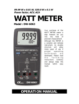
Fig. 1
3. FRONT PANEL DESCRIPTION
Fig
.
1
3-1 Display
3-2 PV ( process value ) indicator
3-3 SV ( set value ) indicator
3-4 Set Button
3-5 Button▼
3-6 Button▲
3-7 PH/Temp Button
3-8 pH control relay indicator
3-9 Temp. control relay indicator
3-10 pH indicator
3-11 Temp. indicator
3-12 Wire terminals
3-13 RS232 terminal
3-14 BNC Input socket
3-15 Case holder
3-16 pH Electrode plug ( optional )
3-17 pH Electrode ( optional )
3-18 Temp. Probe ( optional )
3-19 Temp. Wires ( optional )
5

4. MEASURING PROCEDURE
Terminal layout Fig. 2
4-1 Terminal connection
1)Input the ACV power ( 90 to 260 ACV ) to T1, T2.
Do not input the
over voltage to the
AC input terminals.
2)Connect the " pH Control Relay " output from T3, T4.
Connect the " Temp. Control Relay " output from T5, T6.
4-2 pH calibration
When the first time use the pH electrode or the pH
electrode already be used a long period, then before
the measurement, it should make the
calibration first, the calibration procedures, refer to
page
Chapter 5. pH CALIBRATION PROCEDURES
6

4-3 pH measurement ( with ATC probe )
1)Prepare the optional Temp. probe ( ATC probe TP-07A )
connect the Temp. Wires ( 3-19, Fig. 1 ) to the " Wire
terminals " ( 3-12 ) T10, T9 ( bare wire ).
Prepare the optional pH electrode ( For example PE-21,
PE-03... ), Connect the " pH Electrode plug " ( 3-16,
Fig. 1 ) to " BNC Input socket " ( 3-14, Fig. 1 ).
2)Power on the meter, immerse the above pH electrode
and the Temp. probe into the measuring solution.
The " Display " ( 3-1, Fig. 1 ) will show the pH value,
in the same time the " pH indicator " ( 3-10, Fig. 1 )
will light.
3)Press the " PH/Temp Button " ( 3-7, Fig. 1 ) once,
the " Temp. indicator " ( 3-11, Fig. 1 ) will light, the
" Display " ( 3-1, Fig. 1 ) will show the Temp. value
that sensing from the Temp. probe ( ATC probe
TP-07A ).
* Press the " " PH/Temp Button " ( 3-7, Fig. 1 ) once again,
the " Display " will return the " pH value ", in the
same time the " pH indicator " ( 3-10, Fig. 1 ) will light again.
* The pH measurement value will be compensated automatically
by the Temp. value that sensing from the Temp. probe
( ATC probe, TP-07A ).
* During the Temp. measurement, if intend to change the default
Temp. unit from the to , refer to page 10.℃℉
4-4 pH measurement ( without ATC probe )
1)Prepare the optional pH electrode ( For example PE-21,
PE-03... ), Connect the " pH Electrode plug " ( 3-16,
Fig. 1 ) to " BNC Input socket " ( 3-14, Fig. 1 ).
Not connect the Temp. probe ( ATC probe , TP-07A ) to
the " Wire terminals " ( 3-12 ) T10, T9.
7

2)Power on the meter, Immerse the above pH electrode
into the measuring solution.
The " Display " ( 3-1, Fig. 1 ) will show the pH value,
in the same time the " pH indicator " ( 3-10, Fig. 1 )
will light.
3)Press the " PH/Temp Button " ( 3-7, Fig. 1 ) once,
the " Temp. indicator " ( 3-11, Fig. 1 ) will light, the "
Display " ( 3-1, Fig. 1 ) will show the Manual Temp.
value.
* Press the " " PH/Temp Button " ( 3-7, Fig. 1 ) once again,
the " Display " will return the " pH value ", in the
same time the " pH indicator " ( 3-10, Fig. 1 ) will light again.
* The pH measurement value will be compensated
by the Manual Temp. value.
* The default " Manual Temp. value " is 25 .℃
* The procedures to set the Manual Temp. value, refer
to page 11.
* The method to change the default Manual Temp. unit from the
to , refer to page 10.℃℉
4-5 1st layer setting procedures
LoLt Low Limit
HILt High Limit
Low Limit Value Setting
1)Press the " Set Button " ( 3-4, Fig. 1 ) once, the
" Display " will show " LoLt ", now the meter is ready
for the pH " Low Limit " value setting.
Press the " " PH/Temp Button " ( 3-7, Fig. 1 ) once,
the " Temp indicator " ( 3-11, Fig. 1 ) will light, now
the meter is ready for the Temperature " Low Limit "
value setting.
8

Remark :
* Under " Display " show " LoLt ", if " pH indicator "
( 3-10, Fig. 1 ) is lit, meter is ready for " pH Low
Limit " setting.
* Under " Display " show " LoLt ", if " Temp. indicator "
( 3-11, Fig. 1 ) is lit, meter is ready for " Temperature
Low Limit " value setting.
* The function of " Low Limit value " setting, refer to
page 12, Fig. 2.
2)Use the " " Button " ( 3-5, Fig. 1 ) and the " ▼▲
Button " ( 3-6, Fig. 1 ) to adjust the desiring " Low
Limit " value.
* When adjust the value, the " SV indicator " ( 3-3, Fig. 1 )
will light.
High Limit Value Setting
1)After set the " Low Limit " value, press the " Set
Button " ( 3-4, Fig. 1 ) twice, the " Display " will show
" HILt ", now the meter is ready for the pH " High
Limit " value setting.
Press the " " PH/Temp Button " ( 3-7, Fig. 1 ) once,
the " Temp indicator " ( 3-11, Fig. 1 ) will light, now
the meter is ready for the Temperature " High Limit "
value setting.
Remark :
* Under " Display " show " HILt ", if " pH indicator "
( 3-10, Fig. 1 ) is lit , meter is ready for " pH High
Limit value " setting.
* Under " Display " show " HILt ", if " Temp. indicator "
( 3-11, Fig. 1 ) is lit, it meter is ready for
" Temperature High Limit value " setting.
* The function of " High Limit value " setting, refer to
page 12, Fig. 2.
9

2)Use the " " Button " ( 3-5, Fig. 1 ) and the " ▼▲
Button " ( 3-6, Fig. 1 ) to adjust the desiring " High
Limit " value.
* When adjust the value, the " SV indicator " ( 3-3, Fig. 1 )
will light.
After adjust the " High Limit " value, press the " Set
Button " ( 3-4, Fig. 1 ) twice, " Display " will return to
the normal measuring screen.
4-6 2nd layer setting procedures
tPty Temp. unit setting
tPSt Temp. compensation
value setting
HySt Hysteresis setting
tPoA Temp. Offset setting
PCPS Probe Calibration
Period Setting
Temperature unit setting
1)Press the " Set Button " ( 3-4, Fig. 1 ) continuously at
least two seconds, the " Display " will show " tPty ",
now the meter is ready for the Temperature unit ( ,℃
) setting.℉
2)Use the " " Button " ( 3-5, Fig. 1 ) and the " ▼▲
Button " ( 3-6, Fig. 1 ) to adjust the desiring
temperature unit to " C " or " F ".
* When adjust the Temp. unit, the " SV indicator " ( 3-3, Fig. 1 )
will light.
10

Temp. compensation value setting
The pH measurement value is effected by the
measurement environment Temp. value. If intend to
make the precision pH measurement, it should connect
the Temp. probe ( ATC probe, TP-07A ) to " Wire
terminals " T9, T10. Otherwise, it should adjust the
Temp. compensation values to reach the Temp. values
of the measured solution, the procedures are :
1)After select the temperature unit ( , ), press the℃℉
" Set Button " ( 3-4, Fig. 1 ) twice, the " Display "
will show tPSt ", now the meter is ready for the
the Temp. compensation value setting.
2)Use the " " Button " ( 3-5, Fig. 1 ) and the " ▼▲
Button " ( 3-6, Fig. 1 ) to adjust the desiring
Temp. compensation value.
* If the meter already connect the Temp. probe ( ATC probe,
TP-07A ), though already adjust the Temp. compensation
value, the pH measurement value will be not effected by the
setting Temp. compensation value, it compensated by the Temp.
probe only.
* When adjust the Temp. compensation value, the " SV indicator "
( 3-3, Fig. 1 ) will light.
Hysteresis value setting
1)After select the temperature compensation value,
press the " Set Button " ( 3-4, Fig. 1 ) twice, the
" Display " will show HySt ", now the meter is ready
for the Hysteresis value setting.
2)Use the " " Button " ( 3-5, Fig. 1 ) and the " ▼▲
Button " ( 3-6, Fig. 1 ) to adjust the desiring
Hysteresis setting value.
* When adjust the Hysteresis value, the " SV indicator "
( 3-3, Fig. 1 ) and the " will light.
11

Press the " " PH/Temp Button " ( 3-7, Fig. 1 ) once,
the " Temp indicator " ( 3-11, Fig. 1 ) will light, now
the meter is ready for the Temperature " Hysteresis "
value setting.
Remark :
* Under " Display " show " HySt ", if " pH indicator "
( 3-10, Fig. 1 ) is lit, meter is ready for " pH Hysteresis
value " setting.
* Under " Display " show " HySt ", if " Temp. indicator "
( 3-11, Fig. 1 ) is lit, meter is ready for
" Hysteresis value " setting.
* The function of " Hysteresis value " setting, refer to
page 12, Fig. 2.
Fig. 2
For example :
High limit value : 100
Low limit value : 20
Hysteresis value : 5
a. The control relay will On when measuring value up to 100.
The control relay will Off again when measuring value
down to 95.
b. The control relay will On when measuring value down to 20.
The control relay will Off when measuring value up to 25.
Temp. offset value setting
1)After finish the Hysteresis setting, press the
" Set Button " ( 3-4, Fig. 1 ) twice, the " Display "
will show " tPoA ", now the meter is ready for the
the Temp. offset value setting.
2)Use the " " Button " ( 3-5, Fig. 1 ) and the " ▼▲
Button " ( 3-6, Fig. 1 ) to adjust the desiring
Temp. offset value.
12

* When adjust the Offset value, the " SV indicator " ( 3-3, Fig. 1 )
and Temp. indicator ( 3-11, Fig. 1 ) will light.
Remark :
* For example of " Temp. Offset value setting " :
The Temp. reading value is 18.2
The offset value is 1.1
The new display value will be 19.3 ( 18.2 + 1.1).
Probe Calibration Period Setting ( PCPS )
Typically the pH electrode should be calibrated
after it is used for a certain period.
" Probe Calibration Period Setting function " can set a
period time ( unit is hour, default value is 720 hours ),
then after the pH electrode usage hours reach to setting
PCPS hours, the display reading will present warning
message to inform the user should to execute the new
calibration procedures.
1)After finish the Temp. offset value setting, press the
" Set Button " ( 3-4, Fig. 1 ) twice, the " Display "
will show " PCPS ", now the meter is ready for the
the PCPS value setting.
2)Use the " " Button " ( 3-5, Fig. 1 ) and the " ▼▲
Button " ( 3-6, Fig. 1 ) to adjust the desiring " Probe
Calibration Period Setting value ( PCPS value ) ".
* When adjust the PCPS value, the " SV indicator " ( 3-3, Fig. 1 )
and pH indicator ( 3-10, Fig. 1 ) will light.
* When the meter's usage hours reach to the PCPS value, the
Display will show text " CAL " and the measurement value
in alternation.
* It can reset the usage hours to zero by pressing the
" Set Button " ( 3-4, Fig. 1 ) and the " Button " ▼
( 3-5, Fig. 1 ) at the same time.
13

Note : During the Display show above " CAL " text,
before to reset the usage hours, the user can no
execute the normal function setting.
3)After finish the PCPS value setting, press the
" Set Button " ( 3-4, Fig. 1 ) again, the " Display "
will return to normal measurement screen and finish
the " 2nd layer setting procedures ".
5. pH CALIBRATION PROCEDURES
5-1 Preparation and consideration of pH calibration
1)Prepare the
a. " pH 7 buffer solution " ( optional, such as PH-07. PH-07A )
b. " pH 4 buffer solution " ( optional, such as PH-04. PH-04A )
2)The complete calibration procedures should be
executed by both buffer solution :
a. " pH 7 buffer solution "
b. " pH 4 buffer solution "
3)It should be calibrated under the " pH 7 buffer
solution " at first, then calibrated under the
" pH 4 buffer solution " following.
5-1 pH calibration ( without ATC probe )
1)Power on the meter, immerse the pH electrode
into the standard " Buffer solution ".
The " Display " ( 3-1, Fig. 1 ) will show the pH value
of the buffer solution.
2)Use the two fingers to press " Set Button " ( 3-4, Fig. 1 )
and " Button " ( 3-6, Fig. 1 ) continuously at the▲
same time until the " Display " show the text " CAL "/
Solution Temp. adjustment
Follow the text " CAL " , the display will show the existing
manual Temp. value with flashing, at the same time
" SV indicator " ( 3-3, Fig. 1 ) and the " Temp. indicator "
( 3-11 ) will light.
14

Use the " " Button " ( 3-5, Fig. 1 ) and the " ▼▲
Button " ( 3-6, Fig. 1 ) to adjust the Display until its
value reach to the Temp. value of " Buffer solution ",
then press " Set Button " ( 3-4, Fig. 1 ) will entry the
manual Temp. value.
pH Calibration
After enter the above manual Temp. value, the Display
will show the pH value 7.00 or 4.00 with flashing,
*
Use the pH 7 buffer solution, it will show 7.00
*
Use the pH 4 buffer solution, it will show 4.00
at the same time " SV indicator " ( 3-3, Fig. 1 ) and
the " pH indicator " ( 3-10 ) will light.
* If the aim calibration value is pH 7.00 ( 4.00 )
exactly, then wait about 5 seconds the meter will
entry the calibration value and finish the pH
calibration procedures , the Display will return to
normal screen, the " PV indicator " ( 3-2, Fig. 1 ) will
on, the " SV indicator " ( 3-3, Fig. 1 ) will off.
* If the aim calibration value is not pH 7.00 ( 4.00 )
exactly, during the Display flashing, use the " ▼
Button " ( 3-5, Fig. 1 ) and the " Button " ( 3-6,▲
Fig. 1 ) to adjust Display until it reach to the
pH value of " Buffer solution ", then press " Set
Button " ( 3-4, Fig. 1 ) to entry calibration data. The
Display will return to normal screen, the " PV
indicator " ( 3-2, Fig. 1 ) will On, the " SV indicator "
( 3-3, Fig. 1 ) will off.
During the calibration, if the Display show " Err ",
means pH electrode's output value already beyond
± 1.2 pH and the electrode can not be used any
more, it should change the new electrode.
15

When change the new pH electrode, it recommend
that to execute the " SYSTEM RESET " at first,
refer to page 19.
5-2 pH calibration ( with ATC probe )
1)Power on the meter, immerse the above pH electrode
and the Temp. probe into the measuring solution.
The " Display " ( 3-1, Fig. 1 ) will show the pH value
of the Buffer solution.
2)Use the two fingers to press " Set Button " ( 3-4, Fig. 1 )
and " Button " ( 3-6, Fig. 1 ) continuously at the▲
same time until the " Display " show the text " CAL ",
then present the Temp. value with flashing that
sensing from the Temp. probe ( ATC probe ), after
few seconds ( about 5 seconds ) the Display will change
to the pH value 7.00 or 4.00 with flashing,
*
Use the pH 7 buffer solution, it will show 7.00
*
Use the pH 4 buffer solution, it will show 4.00
at the same time " SV indicator " ( 3-3, Fig. 1 ) and
the " pH indicator " ( 3-10 ) will light.
* If the aim calibration value is pH 7.00 ( 4.00 )
exactly, then wait about 5 seconds the meter will
entry the calibration value and finish the pH
calibration procedures , the Display will return to
normal screen, the " PV indicator " ( 3-2, Fig. 1 ) will
on, the " SV indicator " ( 3-3, Fig. 1 ) will off.
* If the aim calibration value is not pH 7.00 ( 4.00 )
exactly, during the Display flashing, use the " ▼
Button " ( 3-5, Fig. 1 ) and the " Button " ( 3-6,▲
Fig. 1 ) to adjust Display until it reach to the pH
value of " Buffer solution ", then press " Set Button "
( 3-4, Fig. 1 ) to entry calibration data. The Display
will return to normal screen, the " PV indicator "
( 3-2, Fig. 1 ) will On, the " SV indicator " ( 3-3, Fig. 1 )
will off.
16

6. RS232 PC SERIAL INTERFACE
The instrument has RS232 PC serial interface via a 3.5
mm terminal ( 3-13, Fig. 1 ).
The data output is a 16 digit stream which can be
utilized for user's specific application.
A RS232 lead with the following connection will be
required to link the instrument with the PC serial port.
Meter PC
(3.5 mm jack plug) (9W 'D" Connector)
Center Pin..............................
.
Pin 4
Ground/shield........................Pin 2
Pin 5
The 16 digits data stream will be displayed in the
following format :
D15 D14 D13 D12 D11 D10 D9 D8 D7 D6 D5 D4 D3 D2 D1 D0
17
/