Page is loading ...

45060A
Printed in Canada 16-12-2011
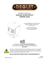
OWNER`S MANUAL
DROLET EPA WOODSTOVES
HT-1600 & HT-2000
US ENVIRONMENTAL PROTECTION
AGENCY PHASE II CERTIFIED
WOODSTOVES
Vérified and/or tested following
ULC S627 et UL 1482 Standards by:
READ AND KEEP THIS MANUAL FOR REFERENCE
Manufactured by: STOVE BUILDER INTERNATIONAL INC.
250, rue de Copenhague, Saint-Augustin-de-Desmaures (Quebec) G3A 2H3
Tel.: 418 878-3040 Fax: 418 878-3001
www.drolet.ca
This manual is available for free download on the manufacturer’s web site. It is a copyrighted
document. Re‐sale is strictly prohibited. Themanufacturermayupdate this manual from time to
time and cannot be responsible for problems, injuries, or damages arising out of the use of
informationcontainedinanymanualobtainedfromunauthorizedsources.


2
TABLE OF CONTENTS
INTRODUCTION .................................................................................................................... 3
TECHNICAL SPECIFICATIONS ............................................................................................ 4
TIPS ON WOOD HEATING .................................................................................................... 5
ASSEMBLY ............................................................................................................................ 6
PEDESTAL AND DECORATIVE SIDEWALL INSTALLATION ................................................. 6
BRICKS AND INSULATION INSTALLATION (HT-1600) ........................................................... 7
BRICK AND INSULATION INSTALLATION (HT-2000) ............................................................. 8
AIR TUBES INSTALLATION (HT-2000): ....................................................................................... 9
DOOR ADJUSTMENT .................................................................................................................... 10
THE BENEFITS OF INSTALLING A BLOWER .................................................................... 11
INSTALLATION .................................................................................................................... 12
POSITIONING THE STOVE ........................................................................................................... 12
CLEARANCES TO COMBUSTIBLES AND FLOOR PROTECTOR ........................................... 13
CHIMNEY ........................................................................................................................................ 20
CHIMNEY CONNECTOR (STOVE PIPE) ..................................................................................... 21
DRAFT .............................................................................................................................................. 23
TYPICAL INSTALLATIONS .......................................................................................................... 24
WOODSTOVE UTILIZATION ............................................................................................... 28
TESTING YOUR WOOD ................................................................................................................. 29
THE FIRST FIRES ........................................................................................................................... 29
IGNITION ......................................................................................................................................... 29
HEATING ......................................................................................................................................... 30
RELOADING .................................................................................................................................... 31
CREOSOTE FORMATION AND NEED FOR REMOVAL ........................................................... 31
ASH DISPOSAL ............................................................................................................................... 32
MAINTENANCE ................................................................................................................... 33
GLASS .............................................................................................................................................. 33
GASKETING .................................................................................................................................... 33
PAINT ............................................................................................................................................... 33
DROLET LIMITED LIFETIME WARRANTY ......................................................................... 34
REGISTER YOU WARRANTY ONLINE
To receive full warranty coverage, you will need to show evidence
of the date you purchased your stove. Keep your sales invoice.
We also recommend that you register your warranty online at
http://www.drolet.ca/en/service-support/warranty-registration
Registering your warranty online will help us track rapidly the
information we need on your stove.

3
INTRODUCTION
SBI INC., one of the most important wood stove and fireplace manufacturers in Canada,
congratulates you on your purchase and wishes to help you get maximum satisfaction from
your wood stove. In the pages that follow, we will give you advice on wood heating and
controlled combustion as well as technical specifications regarding installation, operation
and maintenance of the model you have chosen.
The instructions pertaining to the installation of your wood stove comply with ULC-S627 and
UL-1482 standards.
We recommend that our wood burning hearth products be installed and serviced by
professionals who are certified in the United States by NFI (National Fireplace Institute
®
) or
in Canada by WETT (Wood Energy Technical Training) or in Quebec by APC (Association
des Professionnels du Chauffage).
Read this entire manual before you install and use your new stove. If this stove is not
properly installed, a house fire may result. To reduce the risk of fire, follow the
installation instructions. Failure to follow instructions may result in property
damage, bodily injury, or even death.
Consult your municipal building department or fire officials about restrictions and
installations requirements in your area and the need to obtain a permit.
Keep this instructions manual for future references.
CAUTIONS:
THE INFORMATION GIVEN ON THE CERTIFICATION LABEL AFFIXED TO THE APPLIANCE ALWAYS
OVERRIDES THE INFORMATION PUBLISHED, IN ANY OTHER MEDIA (OWNER’S MANUAL,
CATALOGUES, FLYERS, MAGAZINES AND/OR WEB SITES).
HOT WHILE IN OPERATION. KEEP CHILDREN, CLOTHING AND FURNITURE AWAY. CONTACT MAY
CAUSE SKIN BURNS.
DO NOT USE CHEMICALS OR FLUIDS TO IGNITE THE FIRE.
DO NOT LEAVE THE STOVE UNATTENDED WHEN THE DOOR IS SLIGHTLY OPENED.
DO NOT BURN WASTES, FLAMMABLE FLUID SUCH AS GASOLINE, NAPHTHA OR MOTOR OIL.
DO NOT CONNECT TO ANY AIR DISTRIBUTION DUCT OR SYSTEM.
ALWAYS CLOSE THE DOOR AFTER THE IGNITION.

4
TECHNICAL SPECIFICATIONS
HT-1600 HT-2000
Combustion Type:
Wood Wood
Recommended Surface
900 to 1 800 ft
2
1 000 to 2 400 ft
2
Heating Capacity* : E.P.A :
40 000 BTU/h 60 200 BTU/h
Real : 70 000 BTU/h 95 000 BTU/h
Optimum Efficiency :
76% 78%
Average Emission:
3,5 g/h 3,9 g/h
Colour :
Metallic Black Metallic Black
Flue Pipe Diameter :
6’’ (152 mm) 6’’ (152 mm)
Chimney type : Maximum :
Continuous :
2 100°F (1150°C)
1 200°F (650°C)
2 100°F (1150°C)
1 200°F (650°C)
Minimum Chimney Height :
12’ (3,66 m) 12’ (3,66 m)
Maximum Log Length :
18’’ (457 mm) 22’’ (558 mm)
Dimensions
Overall:
On Pedestal Model :
W x D x H
25 1/8 x 26 ½ x 33 1/4"
(638 x 673 x 844mm)
W x D x H
28 1/8 x 29 3/8 x 34 3/8"
(714 x 746 x 873 mm)
Combustion Chamber :
Width x Depth :
Volume :
18 ¼ x 17 ¼"
(464 x 438 mm)
2,5 pi
3
(0,07 m
3
)
22 7/8 x 20 5/8"
(581 x 524 mm)
3,4 pi
3
(0,09 m
3
)
Door Opening :
Width x Height :
16 ¾ x 8 ¾"
(416 x 222 mm)
17 7/8 x 8 7/8"
(454 x 225 mm)
Pyroceram Glass Door :
Width x Height :
16 3/8 x 9 5/8’’
(416 x 244 mm)
16 3/8 x 9 5/8"
(416 x 244 mm)
Mass:
420 lbs (190 Kg) 550 lb (249 Kg)
OPTIONS
Blower 75 CFM (2,83 m
3
/min) with
variable speed control
Yes
Yes
Thermodisc 100-120
o
F (37-49
0
C). Yes Yes
*Why is the BTU indicated on the EPA label smaller than the one advertised?
You will notice a difference between the BTU output as indicated on the unit’s white EPA label affixed to the glass and
the BTU as advertised on our web site and/or product literature. The maximum BTU output we advertise for this unit is
what will be obtained with a full load of seasoned cordwood inserted inside the firebox. The EPA output, on the other
hand, is what has been obtained during emissions testing. The EPA test procedure requires that a special type of wood
be used and positioned inside the firebox in a manner that does not represent the way the firebox volume would normally
be utilized using seasoned cordwood. The EPA test load is typically much smaller. Hence, the BTU as per the EPA label
is reduced. The BTU output that should be considered by a normal user is the one we advertise for seasoned cordwood.

5
TIPS ON WOOD HEATING
Wood is a renewable energy. It is also a very clean heat source when used with
appliances that are certified by the U.S. Environmental Protection Agency (EPA), a
standard accepted in Canada as well.
EPA-certified wood stoves are different than conventional wood stoves. Burning with an
EPA-certified wood stove may therefore require that you modify some of your heating
habits. To get the most satisfaction out of your new wood-heating system, please make sure
you go through the following check list.
The chimney is the engine that drives the wood-heating system. Use a chimney that
is UL-listed, with an inner diameter to match the stove’s outlet collar (6” for all Drolet
wood stoves);
Try to run the chimney inside the building for as much length as you can. A tall and
warm chimney will produce a good draft;
Try to install your chimney straight up and avoid 90 degree turns in the flue pipe and
offsets in the chimney;
Make sure that the chimney is tall enough and its top is clear of obstacles so it can
produce a stable draft;
Use a chimney thermometer installed at a distance of approximately 18 inches on the
flue pipe above the stove. Flue gases should reach at least 350oF before you close
the stove’s primary air intake completely. Operate your unit within the comfort zone
indicated on the thermometer;
To reduce the risk of smoke spillage into the room upon reloading your stove, leave
the primary air intake completely open for a few minutes. This will heat up the
chimney and build up draft before you open the stove door;
Maximize hot air circulation! Our wood stoves are designed to easily receive a
variable speed blower that will improve heat distribution in front of the stove;
Remember that wood stoves produce radiant heat. Since heat rises, the use of floor
traps will greatly improve the heat transfer to rooms upstairs;
Use a mobile home approved stove if you are going to install your wood-heating
system in a mobile home. A fresh air kit must be connected to the stove. Never install
your wood stove in a bedroom;
Burn only dry cordwood;
Make sure you have a good bed of red coals before you load your stove with logs
exceeding 3 inches in diameter;
Read and keep you owner’s manual. It will provide you with tips on how to run a
successful wood-heating system.

6
ASSEMBLY
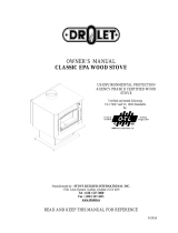
PEDESTAL AND DECORATIVE SIDEWALL INSTALLATION
Pedestal Installation :
1. Remove all bricks and insulations in
the appliance.
2. Slowly, lay down the stove on his
back.
3. Install legs or the pedestal with the
supplied nuts and bolts. Stand up
the stove and place it with the
required clearances. Note that
there is eight holes in the bottom of
the stove but only four will align with
the pedestal.
4. Slide the front part of the pedestal
base around the pedestal and fix
the rear part with the two supplied
screws.
5. Slide the ash pan in position
Figure 1: HT-2000

7
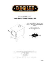
BRICKS AND INSULATION INSTALLATION (HT-1600)
1. Remove from the stove all bricks and insulation.
2. Install all side bricks (11 x 4 1/2" x 9" & 1 x 4 ½” x 8 3/16") as shown in drawing below.
3. Install the back bricks (6 x 4 1/2" x 9")
4. Install the bottom bricks (4 x 4 1/2" x 9") + (2 x 6 " x 8") and the ash cap.
5. Install the "T" shape support.
6. Install the baffle bricks (4 x 4 1/2" x 9") + (2 x 3" x 9") on T shape support.
7. Finally, gently slide the insulation panels over the baffle bricks.
Nbr. Description Qty
1 1 ¼” x 4 ½” x 9” 25
2 1 ¼” x 4 ½” x 8 3/16" 1
3 1 ¼” x 6” x 7" 2
4 ASH CAP (SE09224) 1
5
1 ¼” x 3” x 9"
2
6 ISOLATOR (9 ½" x 12" ) 2
7 SUPPORT (SE09242) 1
Figure 2: HT-1600 Refractory Bricks Assembly

8
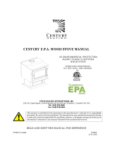
BRICK AND INSULATION INSTALLATION (HT-2000)
The stove is normally supplied with secondary air tubes in position. To install the baffle bricks
and white ceramic insulation, it’s necessary to remove the two front secondary air tubes. First
place only one baffle brick and one white ceramic insulation. Use the same method to put the
other baffle brick and insulation. Put back in place the secondary air tubes.
Install the yellow insulation and the 6" x 8" or 6" x 6" bricks. Install the side and bottom bricks.
Figure 3: HT-2000 Refractory Bricks Assembly
The baffle on the left is not positionned correctly. The baffle on the right is positionned perfectly. It
must be ontop of the bricks and at the rear of the unit.

9
AIR TUBES INSTALLATION (HT-2000):
The secondary air tubes are painted different colours . The back tube is yellow, the middle
on is red and the front is unpainted. Before installing, make sure the locating holes in the
tubes (holes near one end of the tube) are on the left side. Insert one tube in the right side
air channel and slide it to the right as much as possible. Bring the left end of the tube aligned
with the ring welded to the left air channel. Move the tube to the left until the locating holes
are aligned with those in the ring. Insert a cutter pin to hold in place. The air injection holes
should be facing down in the front and middle tubes.
Figure 4: Air Tubes Installation

10
DOOR ADJUSTMENT
In order for your stove to operate properly, the door should be adjusted periodically to
provide an air tight fit. To adjust:
Remove the lock pin (spring pin) by pulling and turning it using pliers ("wise grip")
Turn the handle counter clock wise one turn to increase pressure
Re-install the lock pin (spring pin) with a small hammer
Figure 5: Door Adjustment

11
THE BENEFITS OF INSTALLING A BLOWER
A blower can be installed at the back of your DROLET stove. This option is necessary if you
wish to redistribute into a room the heat trapped at the back of your stove. By forcing hot air
toward the front, the blower enables you to extend the radiation power of your stove.
You can purchase this option through your DROLET dealer. Make sure to specify this part
number: #AC02050. You can also install a thermodisc to enable the blower to start or stop
automatically when the stove is hot or too cold. The thermodisc part number is AC05530.
Installation instructions are supplied with the blower and the thermodisc.

12
INSTALLATION
SAFETY NOTICE
IF THIS STOVE IS NOT PROPERLY INSTALLED, A HOUSE FIRE MAY RESULT. TO REDUCE THE RISK OF
FIRE, FOLLOW THE INSTALLATION INSTRUCTIONS. FAILURE TO FOLLOW INSTRUCTIONS MAY
RESULT IN PROPERTY DAMAGE, BODILY INJURY, OR EVEN DEATH.
CONSULT YOUR MUNICIPAL BUILDING DEPARTMENT OR FIRE OFFICIALS ABOUT RESTRICTIONS AND
INSTALLATIONS REQUIREMENTS IN YOUR AREA.
USE SMOKE DETECTORS IN THE ROOM WHERE YOUR STOVE IS INSTALLED.
KEEP FURNITURE AND DRAPES WELL AWAY FROM THE STOVE.
NEVER USE GASOLINE, GASOLINE-TYPE LANTERN FUEL, KEROSENE, CHARCOAL LIGHTER FLUID, OR
SIMILAR LIQUIDS TO START OR "FRESHEN UP" A FIRE. KEEP ALL SUCH LIQUIDS WELL AWAY FROM
THE STOVE.
IN THE EVENT OF A CHIMNEY FIRE, PUSH THE AIR CONTROL FULL CLOSED TO DEPRIVE THE FIRE OF
OXYGEN. CALL THE FIRE DEPARTMENT.
DO NOT CONNECT TO ANY AIR DISTRIBUTION DUCT OR SYSTEM.
A SOURCE OF FRESH AIR INTO THE ROOM OR SPACE HEATED SHALL BE PROVIDED WHEN
REQUIRED.
POSITIONING THE STOVE
It is very important to position the wood stove as close as possible to the chimney, and in an
area that will favour the most efficient heat distribution possible throughout the house. The
stove must therefore be installed in the room where the most time is spent, and in the most
spacious room possible. Recall that wood stoves produce radiating heat, the heat we feel
when we are close to a wood stove. A wood stove also functions by convection, that is
through the displacement of hot air accelerated upwards and its replacement with cooler air.
If necessary, the hot air distribution from the stove may be facilitated by the installation of a
blower.
The wood stove must not be hooked up to a hot air distribution system since an
excessive accumulation of heat may occur.
A wood stove must never be installed in a hallway or near a staircase, since it may
block the way in case of fire or fall to respect required clearances.

13
CLEARANCES TO COMBUSTIBLES AND FLOOR PROTECTOR
To install your appliance correctly, it is extremely important to respect all clearances to any
combustibles as indicated on your stove’s certification label.
Clearances to combustible materials
(see figure 1.3 to match each letter to a clearance)
CLEARANCES (SINGLE WALL PIPE)
CANADA / USA
MODEL A B C D E F K L
HT-1600
15’’
(385 mm)
16’’
(410 mm)
12’’
(305 mm)
18’’
(460 mm)
26’’
(665 mm)
24’’
(610 mm)
48’’
(1220
mm)
84’’
(213 cm)
HT-2000
19’’
(485 mm)
19’’
(485 mm)
11’’
(280 mm)
23’’
(585 mm)
30’’
(765 mm)
23’’
(585 mm)
48’’
(1220
mm)
84’’
(213 cm)
CLEARANCES (DOUBLE WALL PIPE)
CANADA / USA
MODEL A B C D E F K L
HT-1600
12’’
(305 mm)
16’’
(410 mm)
10’’
(255 mm)
15’’
(385 mm)
26’’
(665 mm)
22’’
(560 mm)
48’’
(1220
mm)
84’’
(213 cm)
HT-2000
10’’
(255 mm)
14’’
(360 mm)
8’’
(205 mm)
14’’
(360 mm)
25’’
(635 mm)
20’’
(510 mm)
48’’
(1220
mm)
84’’
(213 cm)

14
FIGURE 1.3 Clearances to combustible materials and floor protection

15
Floor protector
If the stove is to be installed on top of a combustible floor, it must be guarded by a non
combustible material as shown on figure 1.3 (see the dotted line area).
FLOOR PROTECTOR*
CANADA USA
G
8’’ (205 mm) – Note 1 N/A (Canada only)
H
8’’ (205 mm) N/A (Canada only)
I
18’’ (460 mm)
From door opening
16’’ (410 mm)
From door opening
J
N/A (USA only) 8’’ (205 mm)
M
8’’ (205 mm) N/A (Canada only)
N
N/A (USA only) Note 2
*Steel with a minimum thickness of 0.015’’ (0.38 mm) or ceramic tiles sealed together
with grout. No protection is required if the unit is installed on a non-combustible floor (ex:
concrete).
Note 1 : The floor protection at the back of the stove is limited to the stove’s required
clearance if such clearance is smaller than 8 inches (205 mm).
Note 2 : Only required under the horizontal section of the connector. Must exceed
each side of the connector by at least 2 inches (51 mm).
Reduced clearances using shielding
You may decrease the clearances by installing heat radiation shields between the walls or
the ceiling and the stove. These heat radiation shields must be installed permanently, and
can include sheet metal, a rigid non-combustible sheet or a masonry wall.
Clearances of not less than 1" (25 mm) and not more than 3" (76 mm) between the bottom
of the shield and the floor and not less than 3" (76 mm) between the top of the shield and
the ceiling must be respected to allow vertical air circulation behind the shield. The shield
must extend 20" (500 mm) above the stove top and 18" (450mm) to each side of the stove
(see graphic 1).

16
Following the installation of such a heat radiation shield, the clearances mentioned on the
stove certification plate may be reduced as stated in the following table.
TYPE OF PROTECTION
Reducing Clearances
With Shielding
Sides and
Rear/Back
Top
Sheet metal, a minimum of 0,024" (0,61mm) spaced out
at least 1" (25mm) by non-combustible spacers
(see graphic 2).
67% 50%
Ceramic tiles, or an equivalent non-combustible material
on fire-proof supports spaced out at least 1" (25 mm) by
non-combustible spacers (see graphic 3).
50% 33%
Ceramic tiles, or an equivalent non-combustible material
on fire-proof supports with a minimum of 0,024" (0,61
mm) sheet metal backing spaced out at least 1" (25 mm)
by non-combustible spacers (see graphic 4)
67% 50%
Brick spaced out at least 1" (25 mm) by non-combustible
spacers (see graphic 5)
50% N/A
Brick with a minimum of 0,024" (0,61 mm) sheet metal
backing spaced out at least 1" (25 mm) by non-
combustible spacers (see graphic 6).
67% N/A

17
Graphic 1
A- Minimum clearance required between the appliance and an unshielded combustible
ceiling.
B- 20 in. (500 mm) minimum;
C- 1 in. (25 mm) minimum;
D- Between 1 in. and 3 in. (25 mm and 75 mm);
E- 3 in.(75 mm) minimum;
F- 18 in. (457 mm) minimum.
1- Shielding;
2- Non-combustible spacers;
3- Ceiling protector;
4- Combustible wall;
5- Ceiling;
6- Appliance (side view);
7- Appliance (top view).

18
Graphic 2
A- 1 in.(25 mm) minimum;
1- Combustible wall;
2- Non-combustible spacers;
3- 0.024’’ (0.61mm) sheet metal.
Graphic 3
A- 1 in. (25 mm) minimum;
1- Combustible wall;
2- Non-combustible spacers;
3- Non-combustible support;
4- Ceramic tile or non-combustible material.
Graphic 4
A- 1 in. (25 mm) minimum;
1- Combustible wall;
2- Non-combustible spacer;
3- 0.024’’ (0.61 mm) thick sheet metal;
4- Non-combustible support;
5- Ceramic tile or non-combustible material.

19
Graphic 5
A- 1 in. (25 mm) minimum;
1- Combustible wall;
2- Non-combustible spacers;
3- Brick.
Graphique 6
A- 1 in. (25 mm) minimum;
1- Combustible wall;
2- Non-combustible spacers;
3- 0.024’’ (0.61 mm) thick sheet metal;
4- Brick.
/