Page is loading ...

Crestron CNX-TS
Single Gang Temperature Sensor
Operations & Installation Guide

This document was prepared and written by the Technical Documentation department at:
Crestron Electronics, Inc.
15 Volvo Drive
Rockleigh, NJ 07647
1-888-CRESTRON
All brand names, product names and trademarks are the property of their respective owners.
©2002 Crestron Electronics, Inc.

Crestron CNX-TS Single Gang Temperature Sensor
Contents
Single Gang Temperature Sensor: CNX-TS 1
Introduction......................................................................................1
Features and Functions ..........................................................1
Specifications.........................................................................2
Physical Description ..............................................................2
Industry Compliance..............................................................4
Setup.................................................................................................5
Network Wiring.....................................................................5
Identity Code .........................................................................6
Installation .............................................................................7
Programming....................................................................................8
Programming with SIMPL Windows....................................8
Programming with VT Pro-e ...............................................13
Problem Solving.............................................................................13
Troubleshooting...................................................................13
Further Inquiries ..................................................................14
Firmware Upgrades .............................................................14
Future Updates.....................................................................14
Software License Agreement.........................................................15
Return and Warranty Policies ........................................................17
Merchandise Returns / Repair Service .......................17
CRESTRON Limited Warranty ...................................17
Operations & Installation Guide - DOC. 8173 Contents • i


Crestron CNX-TS Single Gang Temperature Sensor
Single Gang Temperature Sensor:
CNX-TS
Introduction
Features and Functions
The CNX-TS is a wall-mounted single gang temperature sensor that can
be part of a Crestron Home™ total control system. The temperature
sensor is a standard Cresnet device, and provides temperature sensing
when the control system is properly programmed using SIMPL™
Windows
. Multiple sensors can be used in a room to give a more
accurate temperature reading.
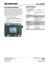
Functional Summary
• Multiple temperature sensors for more accurate reading
• Temperature sensor reports to Cresnet for HVAC monitoring
Operations & Installation Guide - DOC. 8191 Single Gang Temperature Sensor: CNX-TS • 1

Single Gang Temperature Sensor Crestron CNX-TS
Specifications
The following table provides specifications for the sensors.
Specifications for the Sensors
SPECIFICATION DETAILS
Power Re
q
uirements
24 VDC, 0.010A, .25 Watts
Default Network ID
53
Temperature Range
32
o
F - 113
o
F (0
o
C - 45
o
C)
Control System Update Files
1, 2, 3
2-Series Control System Update Version C2-1001.CUZ or later
CEN/CN-TVAV Update File Version 5.10.13V.UPZ or later
CNMSX-AV/Pro Update File Version 5.12.63X.UPZ or later
CNRACKX/-DP Update File Version 5.10.11W.UPZ or later
ST-CP Update File Version 4.02.04S.UPZ or later
Dimensions and Weight Height: 4.76 in (12.1 cm)
Width: 2.91 in (5.57 cm)
Depth: 1.40 in (3.56 cm)
4
Weight: 2.60 oz (75 g)
1 The latest software versions can be obtained from the Downloads | Software Updates section
of the Crestron website (www.crestron.com
). Refer to the NOTE after footnote 4.
2. Crestron 2-Series control systems include the AV2, PAC2, PRO2, RACK2, CP2, and MP2.
3. CNX update files are required for either CNMSX-AV/Pro or CNRACKX/-DP. Filenames for
CNX update files have a UPZ extension, and ST-CP files are in one EXE or zipped UPZ file.
To avoid program problems, make sure you are using the update file with the correct suffix
letter (e.g., S, V, W, X).
4. The depth of the Sensor is listed without the Cresnet connector (approximately 0.45 in) plus
clearance for the wiring.
NOTE: Crestron software and any files on the website are for
Authorized Crestron dealers only. New users may be required to register
to obtain access to certain areas of the site (including the FTP site).
Physical Description
Refer to the illustrations on the next page. The sensor unit consists of a
Cresnet circuit board, a rear speaker, and a male port (standard Cresnet
network port labeled 24 Y Z G). The port provides operating power and
communications to/from the sensor.
2 • Single Gang Temperature Sensor: CNX-TS Operations & Installation Guide - DOC. 8191

Crestron CNX-TS Single Gang Temperature Sensor
The faceplate consists of a removable faceplate that is attached to the
sensor unit.
Temperature Sensor Physical View (with faceplate)
2.912 in*
4.762 in*
12.096 cm
1.067 in
2.710 cm
1.400 in*
3.556 cm
5.568 cm
*Approximate measurements with supplied faceplate, other
faceplates may have different measurements.
Front View
Side Views
Sensor Unit
1.788 in
4.158 in
4.542 cm
10.562 cm
Speaker
Cresnet port
TOP
NET
24 Y Z G
2.710 in
6.884 cm
1.693 in
4.301 cm
Front View
Back View
Static sensitive device, observe
electrostatic discharge (ESD) precautions.
Operations & Installation Guide - DOC. 8191 Single Gang Temperature Sensor: CNX-TS • 3

Single Gang Temperature Sensor Crestron CNX-TS
Installation View
1 in. panhead
Single gang electrical box
(2.5 in. depth recommended)
Sensor unit
Faceplate
Industry Compliance
As of the date of manufacture, the sensors have been tested and found to
comply with specifications for CE marking and standards per EMC and
Radiocommunications Compliance Labelling (N11785).
NOTE: This device complies with part 15 of the FCC rules. Operation is
subject to the following two conditions: (1) this device may not cause
harmful interference, and (2) this device must accept any interference
received, including interference that may cause undesired operation.
4 • Single Gang Temperature Sensor: CNX-TS Operations & Installation Guide - DOC. 8191

Crestron CNX-TS Single Gang Temperature Sensor
Setup
Network Wiring
NOTE: When installing network wiring, refer to the latest revision of
the wiring diagram(s) appropriate for your specific system configuration,
available from the Downloads | Product Manuals | Software and Wiring
Diagrams section of the Crestron website (www.crestron.com)
.
When calculating the wire gauge for a particular Cresnet run, the length
of the run and the power factor of each network unit to be connected
must be taken into consideration. If Cresnet units are to be daisy-chained
on the run, the power factor of each unit to be daisy-chained must be
added together to determine the power factor of the entire chain. If the
unit is a home-run from a Crestron system power supply network port,
the power factor of that unit is the power factor of the entire run. The
length of the run in feet and the power factor of the run should be used in
the following resistance equation to calculate the value on the right side
of the equation.
Resistance Equation
R = Resistance (refer to table below).
L = Length of run (or chain) in feet.
PF = Power factor of entire run
(
or chain
)
.
R <
L x PF
40,000
Where:
The required wire gauge should be chosen such that the resistance value
is less than the value calculated in the resistance equation. Refer to the
table below.
Wire Gauge Values
RESISTANCE (R) WIRE GAUGE
4
16
6
18
10
20
15
22
13
Doubled CAT5
8.7
Tripled CAT5
Operations & Installation Guide - DOC. 8191 Single Gang Temperature Sensor: CNX-TS • 5

Single Gang Temperature Sensor Crestron CNX-TS
NOTE: All Cresnet wiring must consist of two twisted-pairs. One
twisted pair is the +24V conductor and the GND conductor and the other
twisted pair is the Y conductor and the Z conductor.
NOTE: When daisy-chaining Cresnet units, strip the ends of the wires
carefully to avoid nicking the conductors. Twist together the ends of the
wires that share a pin on the network connector, and tin the twisted
connection. Apply solder only to the ends of the twisted wires. Avoid
tinning too far up the wires or the end becomes brittle. Insert the tinned
connection into the Cresnet connector and tighten the retaining screw.
Repeat the procedure for the other three conductors.
Identity Code
Every equipment and user interface within the network requires a unique
identity code (NET ID). These codes are recognized by a two-digit
hexadecimal number from 03 to FE. The NET ID of each unit must
match an ID code specified in the SIMPL Windows program. The NET
ID of the sensor has been factory set to 53. The NET IDs of multiple
sensors in the same system must be unique. NET IDs are changed from a
personal computer (PC) via the Crestron Viewport. Complete the
following procedure to change the NET ID.
NOTE: For detailed information on establishing communication
between the PC and Control System, refer to the network’s Control
System Operations Guide.
1. Ensure that the sensor is the only device connected to the
control system (verify that the software is running).
2. Open the Crestron Viewport.
3. From the Viewport menu, select Functions | Set Network ID.
The software checks the baud rate and then opens the "Set
Network ID" window.
4. In the "Set Network ID" window, select the CNX-TS from the
Current Network Devices text window.
5. From the Choose the new network ID for the selected device
(Hex): text box, select the new NET ID for the sensor.
6. Click Set ID to initiate the change. This will display the "ID
command has been sent" window.
6 • Single Gang Temperature Sensor: CNX-TS Operations & Installation Guide - DOC. 8191

Crestron CNX-TS Single Gang Temperature Sensor
7. In the "Command Complete" window, click OK.
8. In the Current Network Devices text window, verify the new
NET ID code.
9. In the "Set Network ID" window, click Close.
NOTE: The new NET ID code may also be verified by selecting
Diagnostic | Report Network Devices in the Viewport (alternately,
select F4).
10. Repeat this procedure for each sensor to be added to the
system.
Installation
Tools/hardware required
Temperature sensor and faceplate (supplied)
Cresnet network cable
Phillips screwdriver
Two 3/16 in. flathead phillips screws (supplied)
Insulation (not supplied)
NOTE: The insulation will protect the sensor from any in-the-wall
conditions (such as drafts, etc.). Use type in compliance with local codes.
After the Cresnet network wiring has been installed and verified, use the
following procedure to install the sensor (refer to illustration on page 4)
in a single gang electrical box.
1. Turn Cresnet system power OFF.
2. Connect the Cresnet cable with supplied mate to the sensor’s
Cresnet port and the other end to the control system.
3. Insert insulation in electrical box (make sure it fills void of
box not occupied by sensor).
CAUTION: Excess wire that is pinched between the sensor and
electrical box could short out. Make sure that all excess wire is
completely inside the electrical box and not between the box and the
sensor. The CNX-TS contains an electrostatic sensitive device (ESD).
Observe precautions for handling ESDs to avoid damaging unit.
Operations & Installation Guide - DOC. 8191 Single Gang Temperature Sensor: CNX-TS • 7

Single Gang Temperature Sensor Crestron CNX-TS
4. Make sure sensor unit is oriented as marked with arrow at top,
and place it in the electrical box.
5. Attach faceplate and button unit using the supplied (2) 1 in.
panhead screws.
6. Turn Cresnet system power ON.
Programming
You can create a program that allows you to control the sensor through a
Crestron control system using the Crestron programming tool SIMPL™
Windows. This tool is intended for users with different levels of
programming knowledge. The flexibility of the tool is proportional to the
degree of programming expertise (i.e., the more flexible, the more a
programmer needs to know and account for).
NOTE: You can also create and then load a WAV file program (for
sound) in the CNX-TS using VisionTools™ (VT Pro-e).
The following are minimum software version requirements for the PC:
• SIMPL Windows version 2.01.05, or later. Requires SIMPL+
Cross Compiler version 1.1 (Library update file 183 or later)
• VT Pro-e version 2.4 or later
• Crestron Database version 15.7.2 or later (version 15.8.2 if you
use sounds)
Programming with SIMPL Windows
NOTE: The following assumes that the reader has knowledge of SIMPL
Windows. If not, refer to the extensive help information provided with
the software.
NOTE: In the following description, the PRO2 control system is used.
SIMPL Windows is Crestron's software for programming Crestron
control systems. It provides a well-designed graphical environment with
a number of workspaces (i.e., windows) in which a programmer can
select, configure, program, test, and monitor a Crestron control system.
8 • Single Gang Temperature Sensor: CNX-TS Operations & Installation Guide - DOC. 8191

Crestron CNX-TS Single Gang Temperature Sensor
SIMPL Windows offers drag and drop functionality in a familiar
Windows
environment.
This section explains how to create a SIMPL Windows program that
includes a single gang sensor.
Configuration Manager is where programmers “build” a Crestron control
system by selecting hardware from the Device Library. In Configuration
Manager, drag the PRO2 from the Control Systems folder of the Device
Library and drop it in the upper pane of the System Views.
The PRO2 with its associated communication ports is displayed in the
System Views upper pane.
PRO2 System View
The System Views lower pane displays the PRO2 system tree. This tree
can be expanded to display and configure the communications ports.
Expanded PRO2 System Tree
C2Net-Device Slot in Configuration Manager
The C2Net-Device Slot can accept a sensor such as the CNX-TS. Once a
sensor is configured in a C2Net-Device Slot, the slot allows Cresnet
communication between the sensor and the control system.
In Configuration Manager, drag the CNX-TS from the Crestron Control
Modules | Crestron Sensing Modules folder of the Device Library and
drop it on the PRO2 C2Net-Device slot in System Views. The System
Views upper pane displays the CNX-TS device icon below the PRO2
Operations & Installation Guide - DOC. 8191 Single Gang Temperature Sensor: CNX-TS • 9

Single Gang Temperature Sensor Crestron CNX-TS
graphic. The PRO2 system tree as shown on the next page, displays the
sensor in Slot 9, with a default NET ID of 53.
C2Net Device, Slot 9
Double-click the CNX-TS icon in the upper pane to open the “Device
Settings” window. This window displays CNX-TS device information.
The NET ID can be changed in this window using the NET ID tab.
Device Settings Window
NOTE: SIMPL Windows automatically resets the default NET ID
values of a device added to a program if a duplicate device or a device
with the same default NET ID already exists in the program. Always
ensure that the network device NET IDs set via Viewport match the ones
in your SIMPL Windows program.
10 • Single Gang Temperature Sensor: CNX-TS Operations & Installation Guide - DOC. 8191

Crestron CNX-TS Single Gang Temperature Sensor
CNX-TS Symbol in Programming Manager
Programming Manager is where programmers “program” a Creston
control system by assigning signals to symbols. The following graphic
shows the CNX-TS symbol in the SIMPL Windows’ Programming
Manager.
Detail View of the CNX-TS symbol in SIMPL Windows’ Programming
Manager
The following two tables list inputs and outputs, respectively, and their
functional descriptions.
NOTE: All signals listed in the tables are DIGITAL signals unless
noted. A digital signal can be high (logic level of 1), low (logic level of
0), and also have rising edge (when it goes from low to high) and falling
edge (from high to low transitions).
Operations & Installation Guide - DOC. 8191 Single Gang Temperature Sensor: CNX-TS • 11

Single Gang Temperature Sensor Crestron CNX-TS
CNX-TS Symbol Input Signal Descriptions
INPUT DESCRIPTION
Enable_Temp_Rpt Enables temperature reporting to
High/1=reporting enable
Low/0=reporting disable
Temp_Format Controls temperature format.
High/0=Fahrenheit
Low/1=Celsius
Sound20-120* Activates sound file specified by the
corresponding join number in VT Pro-e.
Rising edge starts sound file.
AudioVol (analog) Controls audio volume thru speaker.
Ramp Level=0-100% (If no signal is
connected, default is 0%.)
*Sound20 is the sound assignment to join20. Sounds must be assigned in VTPro-e
and the resulting project loaded. Refer to the VT Pro-e help file for more information.
To create additional sound symbols in SIMPL Windows, right click on the CNX-TS
symbol and select Insert Symbol/Parameter Field (alternatively, select Alt +).
CNX-TS Symbol Output Signal Descriptions
OUTPUT DESCRIPTION
PlayingSound Notifies control system that sound file
is playing.
High/1=playing
Low/0=not playing
Temp(x10) (analog) Reports ambient temperature every 2
seconds (Enable_Temp_Rpt must be
High/1). Units are tenths of a degree,
e.g. 685 is 68.5 degrees.
Example Program
An example program for the sensor is available from the Crestron FTP
site (www.ftp.crestron.com
). Select the Examples folder and search for
CNX-TS.SMW.
12 • Single Gang Temperature Sensor: CNX-TS Operations & Installation Guide - DOC. 8191

Crestron CNX-TS Single Gang Temperature Sensor
Programming with VT Pro-e
To play WAV files, a CNX-TS project must be created in VT Pro-e (with
the WAV files and correct join numbers as part of the project).
NOTE: If you need to create WAV files, refer to Windows Help (Using
Sound Recorder).
NOTE: Join numbers assigned to a WAV file in VT Pro-e begin at 20
because join numbers below 20 are already assigned to other sensor
buttons or functions.
Once the project is created, use File | Upload Project from the VT Pro-e
main menu to load it in the CNX-TS. For more information, refer to the
VT Pro-e help file.
NOTE: This can be done after an identity code (NET ID) is assigned to
the sensor (page 6) or after installation (page 7).
Problem Solving
Troubleshooting
The table below provides corrective action for possible trouble situations.
If further assistance is required, please contact a Crestron customer
service representative.
CNX-TS Troubleshooting
TROUBLE POSSIBLE CAUSE(S) CORRECTIVE ACTION
No temperature
indication.
Wrong NET ID. Poll network. Verify SIMPL
Windows program for setting
Net ID.
Cables not connected or
connected incorrectly.
Check cable connections.
Wrong or incorrect SIMPL
Windows program.
Verify SIMPL Windows
program for enabling sensor.
No sound from
speaker.
Feedback audio signal not
present.
Verify VT Pro-e program for
feedback audio signals.
Operations & Installation Guide - DOC. 8191 Single Gang Temperature Sensor: CNX-TS • 13

Single Gang Temperature Sensor Crestron CNX-TS
Further Inquiries
If after reviewing this Operations and Installation Guide, you cannot
locate specific information or have questions, please take advantage of
Crestron's award winning customer service team by calling:
• In the US and Canada, call Crestron’s corporate headquarters at
1-888-CRESTRON [1-888-273-7876].
• In Europe, call Crestron International at +32-15-50-99-50.
• In Asia, call Crestron Asia at +852-2341-2016.
• In Latin America, call Crestron Latin America at
+5255-5093-2160.
• In Australia and New Zealand, call Creston Pacific at
+613-9480-2999
Firmware Upgrades
To take advantage of all the sensor’s features, it is important that the unit
contains the latest firmware available. Therefore, please check Crestron’s
website (http://www.crestron.com/downloads/software_updates.asp
) for
the latest version of firmware. Not every product has a firmware upgrade,
but as Crestron improves functions, adds new features, and extends the
capabilities of its products, firmware upgrades are posted. If you have
questions regarding upgrades procedures, contact Crestron customer
service.
Future Updates
As Crestron improves functions, adds new features, and extends the
capabilities of the sensors, additional information may be made available
as manual updates. These updates are solely electronic and serve as
intermediary supplements prior to the release of a complete technical
documentation revision.
Check the Crestron website (www.crestron.com
) periodically for manual
update availability and its subjective value. Updates are available from
the Download | Product Manuals section and are identified as an
“Addendum” in the Download column.
14 • Single Gang Temperature Sensor: CNX-TS Operations & Installation Guide - DOC. 8191

Crestron CNX-TS Single Gang Temperature Sensor
Software License Agreement
This License Agreement (“Agreement”) is a legal contract between you (either an individual or a single business entity) and
Crestron Electronics, Inc. (“Crestron”) for software referenced in this guide, which includes computer software and, as applicable,
associated media, printed materials, and “online” or electronic documentation (the “Software”).
BY INSTALLING, COPYING, OR OTHERWISE USING THE SOFTWARE, YOU REPRESENT THAT YOU ARE AN
AUTHORIZED DEALER OF CRESTRON PRODUCTS OR A CRESTRON AUTHORIZED INDEPENDENT PROGRAMMER
AND YOU AGREE TO BE BOUND BY THE TERMS OF THIS AGREEMENT. IF YOU DO NOT AGREE TO THE TERMS OF
THIS AGREEMENT, DO NOT INSTALL OR USE THE SOFTWARE.
IF YOU HAVE PAID A FEE FOR THIS LICENSE AND DO NOT ACCEPT THE TERMS OF THIS AGREEMENT,
CRESTRON WILL REFUND THE FEE TO YOU PROVIDED YOU (1) CLICK THE DO NOT ACCEPT BUTTON, (2) DO NOT
INSTALL THE SOFTWARE AND (3) RETURN ALL SOFTWARE, MEDIA AND OTHER DOCUMENTATION AND
MATERIALS PROVIDED WITH THE SOFTWARE TO CRESTRON AT: CRESTRON ELECTRONICS, INC., 15 VOLVO
DRIVE, ROCKLEIGH, NEW JERSEY 07647, WITHIN 30 DAYS OF PAYMENT.
LICENSE TERMS
Crestron hereby grants You and You accept a nonexclusive, nontransferable license to use the Software (a) in machine
readable object code together with the related explanatory written materials provided by Creston (b) on a central processing unit
(“CPU”) owned or leased or otherwise controlled exclusively by You, and (c) only as authorized in this Agreement and the related
explanatory files and written materials provided by Crestron.
If this software requires payment for a license, you may make one backup copy of the Software, provided Your backup copy
is not installed or used on any CPU. You may not transfer the rights of this Agreement to a backup copy unless the installed copy of
the Software is destroyed or otherwise inoperable and You transfer all rights in the Software.
You may not transfer the license granted pursuant to this Agreement or assign this Agreement without the express written
consent of Crestron.
If this software requires payment for a license, the total number of CPU’s on which all versions of the Software are installed
may not exceed one per license fee (1) and no concurrent, server or network use of the Software (including any permitted back-up
copies) is permitted, including but not limited to using the Software (a) either directly or through commands, data or instructions from
or to another computer (b) for local, campus or wide area network, internet or web hosting services; or (c) pursuant to any rental,
sharing or “service bureau” arrangement.
The Software is designed as a software development and customization tool. As such Crestron cannot and does not
guarantee any results of use of the Software or that the Software will operate error free and You acknowledge that any development
that You perform using the Software or Host Application is done entirely at Your own risk.
The Software is licensed and not sold. Crestron retains ownership of the Software and all copies of the Software and
reserves all rights not expressly granted in writing.
OTHER LIMITATIONS
You must be an Authorized Dealer of Crestron products or a Crestron Authorized Independent Programmer to install or use
the Software. If Your status as a Crestron Authorized Dealer or Crestron Authorized Independent Programmer is terminated, Your
license is also terminated.
You may not rent, lease, lend, sublicense, distribute or otherwise transfer or assign any interest in or to the Software.
You may not reverse engineer, decompile, or disassemble the Software.
You agree that the Software will not be shipped, transferred or exported into any country or used in any manner prohibited
by the United States Export Administration Act or any other export laws, restrictions or regulations (“Export Laws”). By downloading
or installing the Software You (a) are certifying that You are not a national of Cuba, Iran, Iraq, Libya, North Korea, Sudan, or Syria or
any country to which the United States embargoes goods (b) are certifying that You are not otherwise prohibited from receiving the
Software and (c) You agree to comply with the Export Laws.
If any part of this Agreement is found void and unenforceable, it will not affect the validity of the balance of the Agreement,
which shall remain valid and enforceable according to its terms. This Agreement may only be modified by a writing signed by an
authorized officer of Crestron. Updates may be licensed to You by Crestron with additional or different terms. This is the entire
agreement between Crestron and You relating to the Software and it supersedes any prior representations, discussions, undertakings,
communications or advertising relating to the Software. The failure of either party to enforce any right or take any action in the event
of a breach hereunder shall constitute a waiver unless expressly acknowledged and set forth in writing by the party alleged to have
provided such waiver.
Operations & Installation Guide - DOC. 8191 Single Gang Temperature Sensor: CNX-TS • 15

Single Gang Temperature Sensor Crestron CNX-TS
If You are a business or organization, You agree that upon request from Crestron or its authorized agent, You will within
thirty (30) days fully document and certify that use of any and all Software at the time of the request is in conformity with Your valid
licenses from Crestron of its authorized agent.
Without prejudice to any other rights, Crestron may terminate this Agreement immediately upon notice if you fail to comply
with the terms and conditions of this Agreement. In such event, you must destroy all copies of the Software and all of its component
parts.
PROPRIETARY RIGHTS
Copyright. All title and copyrights in and to the Software (including, without limitation, any images, photographs,
animations, video, audio, music, text, and “applets” incorporated into the Software), the accompanying media and printed materials,
and any copies of the Software are owned by Crestron or its suppliers. The Software is protected by copyright laws and international
treaty provisions. Therefore, you must treat the Software like any other copyrighted material, subject to the provisions of this
Agreement.
Submissions. Should you decide to transmit to Crestron’s website by any means or by any media any materials or other
information (including, without limitation, ideas, concepts or techniques for new or improved services and products), whether as
information, feedback, data, questions, comments, suggestions or the like, you agree such submissions are unrestricted and shall be
deemed non-confidential and you automatically grant Crestron and its assigns a non-exclusive, royalty-tree, worldwide, perpetual,
irrevocable license, with the right to sublicense, to use, copy, transmit, distribute, create derivative works of, display and perform the
same.
Trademarks. CRESTRON and the Swirl Logo are registered trademarks of Crestron Electronics, Inc. You shall not remove
or conceal any trademark or proprietary notice of Crestron from the Software including any back-up copy.
GOVERNING LAW
This Agreement shall be governed by the laws of the State of New Jersey, without regard to conflicts of laws principles.
Any disputes between the parties to the Agreement shall be brought in the state courts in Bergen County, New Jersey or the federal
courts located in the District of New Jersey. The United Nations Convention on Contracts for the International Sale of Goods, shall
not apply to this Agreement.
CRESTRON LIMITED WARRANTY
CRESTRON warrants that: (a) the Software will perform substantially in accordance with the published specifications for a
period of ninety (90) days from the date of receipt, and (b) that any hardware accompanying the Software will be subject to its own
limited warranty as stated in its accompanying written material. Crestron shall, at its option, repair or replace or refund the license fee
for any Software found defective by Crestron if notified by you within the warranty period. The foregoing remedy shall be your
exclusive remedy for any claim or loss arising from the Software.
CRESTRON shall not be liable to honor warranty terms if the product has been used in any application other than that for
which it was intended, or if it as been subjected to misuse, accidental damage, modification, or improper installation procedures.
Furthermore, this warranty does not cover any product that has had the serial number or license code altered, defaced, improperly
obtained, or removed.
Notwithstanding any agreement to maintain or correct errors or defects Crestron, shall have no obligation to service or
correct any error or defect that is not reproducible by Crestron or is deemed in Crestron’s reasonable discretion to have resulted from
(1) accident; unusual stress; neglect; misuse; failure of electric power, operation of the Software with other media not meeting or not
maintained in accordance with the manufacturer’s specifications; or causes other than ordinary use; (2) improper installation by
anyone other than Crestron or its authorized agents of the Software that deviates from any operating procedures established by
Crestron in the material and files provided to You by Crestron or its authorized agent; (3) use of the Software on unauthorized
hardware; or (4) modification of, alteration of, or additions to the Software undertaken by persons other than Crestron or Crestron’s
authorized agents.
ANY LIABILITY OF CRESTRON FOR A DEFECTIVE COPY OF THE SOFTWARE WILL BE LIMITED
EXCLUSIVELY TO REPAIR OR REPLACEMENT OF YOUR COPY OF THE SOFTWARE WITH ANOTHER COPY OR
REFUND OF THE INITIAL LICENSE FEE CRESTRON RECEIVED FROM YOU FOR THE DEFECTIVE COPY OF THE
PRODUCT. THIS WARRANTY SHALL BE THE SOLE AND EXCLUSIVE REMEDY TO YOU. IN NO EVENT SHALL
CRESTRON BE LIABLE FOR INCIDENTAL, CONSEQUENTIAL, SPECIAL OR PUNITIVE DAMAGES OF ANY KIND
(PROPERTY OR ECONOMIC DAMAGES INCLUSIVE), EVEN IF A CRESTRON REPRESENTATIVE HAS BEEN ADVISED
OF THE POSSIBILITY OF SUCH DAMAGES OR OF ANY CLAIM BY ANY THIRD PARTY. CRESTRON MAKES NO
WARRANTIES, EXPRESS OR IMPLIED, AS TO TITLE OR INFRINGEMENT OF THIRD-PARTY RIGHTS,
MERCHANTABILITY OR FITNESS FOR ANY PARTICULAR PURPOSE, OR ANY OTHER WARRANTIES, NOR
AUTHORIZES ANY OTHER PARTY TO OFFER ANY WARRANTIES, INCLUDING WARRANTIES OF
MERCHANTABILITY FOR THIS PRODUCT. THIS WARRANTY STATEMENT SUPERSEDES ALL PREVIOUS
WARRANTIES.
16 • Single Gang Temperature Sensor: CNX-TS Operations & Installation Guide - DOC. 8191
/