Page is loading ...

THE STERO COMPANY
DOOR TYPE UTENSIL
WASHER
PARTS MANUAL
TOLL FREE CALL 8OO -762-7600

Installation, Operation and Care of
UTENSIL
SAVE THESE INSTRUCTIONS
GENERAL
Utensil Washer is a semi-automatic rack-type washer. It uses a 3 phase 3 H.P. motor.
The fill line incorporates an atmospheric vacuum breaker to prevent any reverse flow of water from the utensil
washer into the potable water supply.
A float, located in the wash tank, will shut off the heat supply if the water level becomes too low. When the water
returns to a safe level, the heating circuit is again operational.
INSTALLATION
UNPACKING
Immediately after unpacking, the machine should be checked for possible shipping damage. If this machine is found
to be damaged after unpacking, save the packing material and contact the carrier within 15 days of delivery.
When lifting the washer with a hi-lift or forklift, be sure to place the forks in such a position that the drain assembly
beneath the tank is not damaged.
Prior to installation, test the electrical service to assure that it agrees with the specifications on the machine data
plate located on the side of the control box.
LOCATION
Place the machine in its operating position. Before finalizing location, make sure that consideration has been given
for electrical conduit, water supply, drain connections, steam supply (if applicable), tabling, and adequate clearance
for opening the door.
The utensil washer must be level before any connections are made. Turn the threaded feet as required to level the
machine and adjust to the desired height.
A hood or vent may be required in order to meet local codes.
—3—

PLUMBING
WARNING: PLUMBING CONNECTIONS MUST COMPLY WITH APPLICABLE SANITARY, SAFETY, AND
PLUMBING CODES.
Drain
The drain connection is made using 2" pipe.
Water Supply
The water supply line is connected to the line strainer with 3/4" pipe. The water supply line is located on top of the
machine at the rear (see Fig. 1).
Minimum water temperatures are: 150°F wash and 180°F rinse.
Proper utensil washer operation requires a flowing pressure of 20 ± 5 p.s.i. at the washer. If the flowing pressure
exceeds 25 p.s.i., a pressure reducing valve (not supplied) must be installed in the water supply line.
A pressure gauge (Fig. 1) is provided for verification of proper water pressure. Refer
to the floor plans on Pages 10 & 11 for plumbing information.
ELECTRICAL CONNECTIONS
WARNING: ELECTRICAL AND GROUNDING CONNECTIONS MUST COMPLY WITH THE APPLICABLE PORTIONS OF THE
NATIONAL ELECTRICAL CODE AND/OR OTHER LOCAL ELECTRICAL CODES.
WARNING: DISCONNECT ELECTRICAL POWER SUPPLY AND PLACE A TAG AT THE DISCONNECT SWITCH INDICATING
THE CIRCUIT IS BEING WORKED ON.
A fused disconnect switch or circuit breaker (not supplied) must be installed in each electrical service line supplying this utensil
washer and should meet the requirements of your local electrical code. There is one service connection for the motors and
controls. A second service connection is required for machines with electric tank heat.
All connections are made at the terminal block in the control box. Connect a permanent electrical power supply to the incoming
power supply block, and connect a ground lead to the grounding lug in the control box if grounding is not provided by the conduit
used.
—4—

Three-phase motors must rotate in the direction of the arrow on the pump housing. In order to check rotation, close
the machine doors and press the FILL button on the control box (See Fig. 3). When the machine is completely filled,
turn the manual WASH/RINSE switch (Fig. 3) to WASH. Watch the motor output shaft where it enters the pump
housing. The motor shaft must rotate in the direction of the arrow on the pump motor housing.
If the rotation is incorrect, DISCONNECT ELECTRICAL POWER SUPPLY and interchange any two of the incoming
motor power supply leads. Re-energize the washer and verify correct rotation.
The wiring diagram is located inside the control box. Refer to the floor plans on pages 10 & 11 for any additional electrical
information.
OPERATION
PREPARATION
Place the two strainers and tank spacer in position (Fig. 4).
Scatter the initial charge of detergent on the strainers. Replenish as needed. If an automatic detergent dispenser has
been added, follow supplier's instructions.
Turn the DRAIN VALVE HAND KNOB (Fig. 2) clockwise to the CLOSED position. Close
the counterbalanced doors.
Press the FILL button on the control box (Fig. 3). The red pilot light will be illuminated until the tank has been filled.
Once the machine has been filled, turn the TANK HEAT switch (Fig. 3) to ON. The red HEAT light will be illuminated and
the heater will maintain the wash water temperature at a minimum of 150°F.
—5—

UTENSIL WASHING
Thoroughly scrape the utensils to remove large particles of food and debris.
Fill the utensil rack, raise the counterbalanced doors, slide the rack into the machine, and close the doors.
Automatic Operation
Set the WASH/RINSE switch (Fig. 3) to OFF. Push the START button and the machine will automatically run
through a 128-second wash cycle, immediately followed by a 15-second rinse cycle. The WASH and RINSE red
lights will be illuminated during their respective cycles. The automatic cycle times are preset at the factory;
however, if necessary, they may be increased. Contact your local Service Office.
Manual Operation
Set the WASH/RINSE switch (Fig. 3) to WASH. The machine will continue to wash as long as the switch is in
this mode. When ready to rinse, hold the WASH/RINSE switch in the RINSE position for the desired rinse time.
The manual mode of operation is recommended for heavily soiled utensils.
The machine is equipped with a door interlock switch. When the doors are open, the control circuit is interrupted and
the machine will not operate. If a cycle is interrupted before completion, pushing the START button will begin the
entire wash/rinse cycle over again.
When the wash and rinse cycles are finished, raise the counterbalanced doors, remove the clean utensils, slide in
another rack, and close the doors.
Wash water in the utensil washer should be changed after each peak period.
Strainers should be emptied and rinsed before they fill up with food soils. Plugged strainers interfere with the return
of the wash water to the pump, contribute to foaming, and starve out the pump spray action, creating poor results
and high detergent costs.
—6—

MAINTENANCE
WARNING: DISCONNECT ELECTRICAL POWER SUPPLY AND PLACE A TAG AT THE DISCONNECT SWITCH
INDICATING THE CIRCUIT IS BEING WORKED ON BEFORE BEGINNING ANY MAINTENANCE PROCEDURE.
MOTOR
The motor has sealed bearings and, therefore, requires no lubrication maintenance.
WASH ARMS
Both wash arms and the lower rinse arm (Fig's. 4 & 5) should turn freely and continue turning for a few seconds after
being whirled by hand. To check, DISCONNECT ELECTRICAL POWER SUPPLY, rotate arms, and remove any
obstructions causing improper operation.
If the strainers are not properly in place, obstructions (such as food particles) may clog the wash arm nozzles.
CLEANING
It is recommended that the machine be thoroughly cleaned at the end of each working shift or at least daily.
DISCONNECT ELECTRICAL POWER SUPPLY to the unit.
Turn TANK HEAT switch to OFF.
Open machine doors.
Clean off tables into the utensil washer.
Drain the machine by turning the DRAIN VALVE HAND KNOB (see Fig. 2) counterclockwise to the OPEN position.
Remove and empty the strainers. Wash and rinse them thoroughly.
Check wash arm and rinse arm nozzles (Fig's. 4 & 5) to make sure they are free of any lime and solids. The wash
arms are easily removed for cleaning.
-7-

Lift lower rinse arm off the rinse pin (Fig. 4). Inspect sprayers to be sure orifices are clean and clear of scale.
Lift off lower wash arm (Fig. 4). If sprayers are clogged with debris, remove the end cap, push the debris
clogging the nozzle back into the arm and rinse out the arm.
Unscrew the upper wash arm retaining disc (Fig. 5) and remove the arm, being careful not to drop it. Follow the
same cleaning procedure as for the lower wash arm.
Check the four stationary corner rinse nozzles at the top of the machine to make sure they are free of lime and
solids.
Thoroughly cleanse and flush the utensil washer interior, including the insides of the doors.
Replace the wash and rinse arms. Spin each wash arm and the rinse arm to be sure they rotate freely and are free
of any obstructions.
Replace the strainers.
Wash the exterior of the machine with a clean damp cloth. Dry with a soft clean cloth.
Leave the machine doors open to allow the interior to dry and air out.
Leave the drain valve open until ready to fill for next use.
—8—

TROUBLESHOOTING
This section provides simple operator-oriented troubleshooting tips. Should you encounter any of the symptoms listed in this
section, check the possible causes — this might eliminate the need for a service call. If a symptom persists after the possible
causes have been checked, contact your local Service Office.
SYMPTOM — No machine operation
POSSIBLE CAUSE:
1. Blown fuse or tripped circuit breaker at power supply.
2. Check tank water level.
3. Doors open.
SYMPTOM — No wash tank heat
POSSIBLE CAUSE:
1. The machine is equipped with a low water safety device which shuts off heat if the water level drops. Check for proper
water level.
2. Circuit breaker to machine tripped.
SYMPTOM — No or slow fill
POSSIBLE CAUSE:
1. Circuit breaker off.
2. Doors open.
3. Drain valve open.
4. Dirty line strainer causing reduced water flow. Turn off water supply remove strainer cap, withdraw and clean screen.
Reassemble.
SYMPTOM — Tank water leaking
POSSIBLE CAUSE:
1. Check drain for possible obstructions.
—9—

INSTRUCTIONS FOR
FENWAL
DIFFERENTIAL EXPANSION
THERMOSWITCH UNITS
PRINCIPLE OF OPERATION:
The Thermoswitch Control is constructed with two silver contacts mounted on, but electrically
insulated from, curved struts of low expansion coefficient. This assembly is mounted under tension or
compression in a seamless drawn brass or stainless steel tube. Changes in temperature cause the shell
to expand or contract, which exerts more or less tension or compression on the struts, causing the
contacts to make or break.
BASIC TYPES:
The shell of the Thermoswitch Control contains information regarding electrical rating,
temperature range, and contact action. Should the shell of the unit be inserted, immersed, or otherwise
obscured in such a manner as to make reference to this impossible, general operating characteristics may
be quickly determined if the catalogue number of the device is known. If the 5th digit of the catalog
number is even (or zero), the contacts close on the decreasing temperatures. If the 5th digit of the
catalog number is odd, the contacts close on increasing temperatures. Reference to the fourth digit
will quickly determine whether the unit is tension or compression operated. Should this digit be "2" or
"7", the unit is compression operated, should it be other than "2" or "7", the unit is tension operated.
Tension operated units may be subjected to momentary temperature exposure of 100°F above their set point.
They also may be subjected to any temperature below their set point without danger. Tension operated
Fenwal Thermoswitch units may be set below 0°F but compression operated units are recommended if rapid
temperature changes in excess of 100F or extreme temperature overshoots are to be encountered. Fenwal
compression operated units may be exposed to a temperature of 100°F indefinitely, and to temperatures
400°F above their set temperatures for short periods of time. The limits of exposure being subject to
many application variations. When in doubt, the factory should be consulted.
INSTALLATION & ADJUSTMENT TIPS
THE HEX HEAD OR THREADED TYPE can be installed like any pipe fitting. Avoid applying undue torque to the
unit. Torque in excess of 35 foot pounds for the standard size (5/8" dia. shell) or 70 root pounds for
the heavy duty (13/16" diam. shell) will offset the control calibration. If threaded units are
installed in a pipe tee, the tee should be large enough Co allow adequate circulation of the fluid
around the temperature sensitive section of unit.
10

DON'TS
Do not handle the unit: with pliers or force it: into position either by hand or with tools, or apply excessive torque in- tightening
threaded units. Do not subject unit to deformation of :he shell. Do not thermally shield unit from medium it is to control.
TESTING & ADJUSTING
The arrow on the head of THERMOSWITCH units indicated direction in which adjusting screw should be turned to increase the
temperature setting. Each full turn of the adjusting screw will change the temperature the approximate number of degrees indicated by the table.
After the THERMOSWITCH unit has been installed, final adjustment can be made by allowing the unit to operate for several cycles
to permit the controlled system to stabilize and then adjust ;o desired temperatures. The system should then be cooled Co ambient temperature,
reheated and stabilized to check the setting.
Where extremely accurate temperature control is desired, several read-adjustments may be necessary to stabilize the
THERMOSWITCH Control after which the adjustment will be maintained.
CAUTION
DO NOT turn the adjusting screw in any further than is necessary for operation. Do not remove adjusting screw from unit as ;his
voids the Standard Guarantee. Incorrect replacement or over adjustment will permanently damage the element assembly.
TURN ADJUSTMENT SCREW CLOCKWISE TO RAISE TEMPERATURE
11

UTENSIL WASHER
TABLE OF CONTENTS
DESCRIPTION
STRUCTURAL COMPONENTS
FRAME 1
TANK 3
HOOD 5
DOOR ASSEMBLY 7
TRACKS 9
STRAINER PANS 11
RACKS
13
PUMPING SYSTEMS
3 HP PUMP ASSEMBLY 15
MOTOR ASSEMBLY 17
SPRAYING SYSTEMS
WASH 19
RINSE 21
HEATING COMPONENTS
STEAM HEAT 23
ELECTRIC HEAT 25
PLUMBING COMPONENTS
BOOSTERS 27
SPIREC ASSEMBLY 29
THRUSH ASSEMBLY 31
ELECTRIC ASSEMBLY 33
FINAL RINSE 35
COMMON PARTS 37-39

TABLE OF CONTENTS
(CONTINUED)
DESCRIPTION PAGE
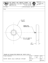
DRAIN AND OVERFLOW 41
GAUGE ASSEMBLY 43
ELECTRICAL SYSTEMS
CONTROL BOX 45
FLOAT SWITCH 47
THERMOSTATS 49
COMMON FITTINGS 51

1

FRAMES
ITEM DESCRIPTION REMARKS PART NO.
1 FRAME, STRAIGHT THRU U-31A A10-2729
2 FRAME, STRAIGHT THRU U-31A2 A10-2761
3 FRAME. CORNER TYPE U-31AC LEFT OR RIGHT
B10-3912
4 FOOT, ADJUSTABLE S.S. B10-3915
* TD DRDER SUPPLY MACHINE MODEL AND SERIAL NUMBER 2

3

TANKS
ITEM DESCRIPTION REMARKS PART NO.
1 TANK, STRAIGHT THRU U-31A
B10-2728
2 TANK, STRAIGHT THRU U-31A2
B10-2760
3 TANK, CORNER U-31AC RIGHT-LEFT * A10-5109
4 TANK, CORNER U-31AC LEFT-RIGHT * A10-5109
* TO ORDER SUPPLY MACHINE MODEL AND SERIAL NUMBER


HOODS
ITEM DESCRIPTION REMARKS PART NO.
1 STRAIGHT THRU, U-31A
B10-2726
2 VENT DAMPER U-31A2
A10-4217
3 STRAIGHT THRU U-31A2
B10-2759
4 VENT U-31A2
A10-5114
5 CORNER U-31AC RIGHT-LEFT
A10-3924
6 POST, CORNER RIGHT-LEFT
A10-3918
7 VENT DAMPER
A10-2775
8 VENT
B10-2774
9 CORNER U-31AC LEFT-RIGHT
A10-5112
10 POST, CORNER LEFT-RIGHT
A10-5113
* TO ORDER SUPPLY MACHINE MODEL AND SERIAL NUMBER 6


TYPICAL DOOR ASSEMBLY
ITEM DESCRIPTION REMARKS PART NO.
1 CABLE, U-31A
A10-2739
CABLE, U-31A2
A10-2741
CABLE, U31AC
A10-2740
2 BRACKET, ROD SUPPORT
A10-2749
3 ROD, WEIGHT GUIDE RIGHT SIDE
A10-2748
4 ROD. WEIGHT GUIDE LEFT SIDE
A10-2747
5 DOOR ANGLE
A10-2736
6 RETAINER, CORNER POST U-31AC LEFT-RIGHT
A10-5116
7 RETAINER, CORNER POST U-31AC RIGHT-LEFT
A10-3919
8 RETAINER, LEFT-REAR. RIGHT-FRONT
A10-2769
9 RETAINER, RIGHT-REAR. LEFT-FRONT
A10-2770
10 SPACER, DOOR GUIDE
A10-4215
11 TEFLON, UPPER CORNER POST (FDR #7)
A10-5120
12 TEFLON, UPPER CORNER POST (FOR #6)
A10-5121
13 TEFLON, UPPPER CORNER POST (FOR #8 & 9)
A10-2771
14 CORNER POST, U-31AC RIGHT-LEFT
A10-3918
15 CORNER POST, U-31AC LEFT-RIGHT
A10-5113
16 COUNTER WEIGHT
A10-2746
17 DOOR GUIDE
A10-2727
DOOR, SIDE ALL MODELS
A10-2734
18 DOOR, FRONT U-31AC ONLY
A10-3920
19 TEFLON, LOWER DOOR
A10-1536
20 RETAINER, TEFLON LOWER DOOR
A10-2772
21 HANDLE, DOOR
B10-1448
22 SPLASH GUARD, SIDE DOORS 25" LONG
A10-3921
SPLASH GUARD, FRONT DOOR 27" LONG
A10-3922
23 GASKET
A10-5118
24 BRACKET, SHEAVE
A10-2743
25 SHEAVE
A66-2742
26 BRACKET, CABLE RETAINER
A10-2745
27 MAGNET ASSEMBLY
B10-4274
28 REED SWITCH ASSEMBLY
A10-4275
* TO ORDER SUPPLY MACHINE MODEL AND SERIAL NUMBER
/