Page is loading ...

INSTRUCTION AND PARTS MANUAL
STERO MODEL SGW-M GLASS WASHER
WITH MECHANICAL TIMER
AND
STERO MODEL SGW-H-M WITH OPTIONAL PRE-HEATER
AND MECHANICAL TIMER
INTRODUCTION
Careful attention to these Instructions
will insure long and satisfactory service
from the Stero Glass Washing Machine.
SECTION 1
Installation Instructions
Operation
Adjustments
Maintenance
Trouble Shooting Guide
SECTION 2
Parts Drawings Parts
Numbers & Description
Wiring Diagram
1

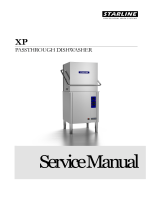
STERO GLASS WASHER SGW
DRAIN-2-1/4 I.D. HOSE CONNECTION
1 ONLY-
115V. ELECTRICAL FEEDER
1/3 H.P. MOTOR-115 V.-10 AMPS
2 K-W. HEATER (OPTIONAL) 115V.-17.4 AMPS
3/8" NPT WATER SUPPLY-120° MIN.
2

INSTALLATION INSTRUCTIONS
1. Set machine in place.
Level machine side to side and front to back.
A. Level adjustment made by screwing adjustable feet in or out as necessary.
2. Make final plumbing and electrical connections per tags attached to connection points. (See page 2).
A. Plumbing connections.
1. One (1) 3/8" N.P.T. 140° water supply.
NOTE: Install shut off valve prior to machine connection.
2. One (1) 2 1/4" I.D. hose drain connection.
B. Electrical connections.
NOTE: ALL STERO GLASS WASHERS A RE 115 VOLT, SINGLE PHASE.
1. The terminal strip is located in the control box and is marked LI N. A knock-out is provided in the bottom of the
control box for your electrical conduit.
2. Some glass washers are equipped with an optional 2 K.W heater to maintain water temperatures at between 120° and
140° f. (Model SGW-H).
NOTE: See name plate on door of the machine and size circuit breaker and wire accordingly.
COMPLY WITH LOCAL ELECTRICAL CODES.
OPERATION: START-UP
1. Make sure drain plug is seated in
drain.
2. Pump intake screen in place.
3. Fill the machine by pressing fill
toggle switch to left.
NOTE: Fill to 1/2" below overflow.
4. Be sure revolving wash arm is in
place with end caps tightly
secured—spin to test for free
rotation.
5. Set thermostat at 140° (when
equipped with optional pre-heater).
See Fig. 1
6. Close door—press start switch and
hold down for 2 to 5 seconds—door
must be closed as machine is
equipped with a door safety switch.
7. Stop Run Hold switch must be in
center (run) position. Hold position
will stop the cycle timer in whatever
cycle the machine is running. This is
primarily for processing the glasses
and/or chemically cleaning the
machine.
3

SEQUENCE OF EVENTS
1. Wash cycle-40 seconds.
A. Detergent dispensing pump is energized during wash
cycle.
2. Drain-11 seconds.
3. Flush-4 seconds. (Before the drain closes, the fill solenoid
valve will open. The pump motor will come on and the
machine will be flushed of any debris or detergent residue).
4. Fill-Drain closes at end of 4 seconds. Flush and fills to proper
level – ½" below overflow. This time depends on water
pressure of supply - approximately 15 seconds.
A. Sanitizer and rinse aid pumps activated during fill and
rinse.
5. Rinse-20 seconds.
ADJUSTMENTS
The machine has been thoroughly tested and adjustments have
been made at the factory. Due to differences in water pressure,
the water level may have to be adjusted. This is done by
removing the cover from the pressure switch, located behind
the front panel, between the start switch and temperature
gauge. Turn the adjustment screw clockwise to raise the water
level, counter-clockwise to lower water level.
CHEMICAL DISPENSING SYSTEM
Your glass washer is equipped with a complete liquid chemical dispensing system, consisting of the following:
1. Three (3) peristaltic pumps with color coded tubing.
A. Detergent - Red tubing
B. Sanitizer - White tubing
C. Rinse Aid - Blue tubing
2. Chemical Adjustments.
All chemicals are produced in varying concentrations and therefore, the chemical supplier MUST adjust the dispensers
to deliver the proper amount of chemical required to give good results.
4

CHEMICAL ADJUSTMENTS (Cont.)
To adjust the amount of chemical dispensed, locate the appropriate cam on the 7 cam mechanical timer. Turn the right side of
this cam with the timer wrench. Opening the gap will increase the amount of chemical dispensed. The timer is shown in Fig.
2.
NOTE: Excessive rinse aid will cause foaming. Foam reduces the wash and rinse pressure to an unacceptable level. If foam is observed on glasses or in
machine, check water temperature. If above 120°, have the chemical supplier decrease quantity of rinse additive being injected.
NOTE: Chlorine concentration should be kept at 50 PPM. Excessive chlorine will create a chlorine odor around the machine area and cause a
cloudy grey film to appear on the clean glassware.
CAUTION: Chlorine is corrosive. Excessive concentrations will damage your glass washer.
MAINTENANCE
Your new SGW-M is easy to maintain.
Since soils, washed from the glassware are discharged from the machine during the drain and flush cycle
the interior of the machine remains relatively clean.
DAILY MAINTENANCE
1. Remove and inspect the spray area, paying close attention to the sprayers to see that they are free of any debris that might
interrupt the spray pattern. If a sprayer is clogged, simply loosen the wash arm end caps, push the debris back through the
sprayer, into the wash arm and rinse out. Be sure slot in arm. bushing is clean.
2. Remove and clean pump intake screen.
3. Remove and clean scrap screen from drain sump.
4. Check level of chemical containers, replace as necessary. When replacing chemical containers use prime switch to prime
the pumps. Operate the machine several times after priming the chlorine sanitizer pump. This will wash the concentrated
chlorine off of the interior of the glass washer.
Now that all spray jets, pump intake screen and drain sump screen have been cleaned, replace as follows:
1. Replace scrap screen in drain sump.
2. Replace pump intake screen.
3. Replace spray arm.
NOTE: Be sure spray arm bushing and pivot pin are free of any grit that may slow down or keep the spray arm from revolving.
WEEKLY (or as necessary):
1. Remove the scrap screen from the drain sump and thoroughly clean the interior of the drain sump. This cleaning is
necessary to avoid any odors created by scrap which may have been allowed to fall from the scrap screen into the sump
itself.
MONTHLY:
1. Remove four spray jets from upper spray jet manifold and clean if clogged.
5

SGW AND SGW-H DISHWASHERS - TROUBLE SHOOTING GUIDE
PROBLEM LOOK FOR CORRECTION
MACHINE WILL NOT FILL
1) Closed water supply valve.
2) Plugged line strainer.
3) Defective pressure switch.
4) Defective till valve.
5) Drain valve open.
6) Defective fill switch.
7) Defective Timer.
1) Open valve.
2) Remove & clean screen.
3) Check & replace if necessary.
4) Check & replace if necessary.
5) Check seat for food particles, check "0"
ring (broken or out of place).
6) Replace fill switch.
7) Check fill Micro Switch on Timer.
MACHINE WILL NOT START
1) Tripped circuit breaker.
2) Defective door switch.
3) Stop-Run-Hold switch not in run position.
4) Start Switch not depressed long enough.
1) Reset breaker in customer breaker panel.
2) Check & replace if necessary.
3) Switch to run.
4) Hold start switch in for 5 seconds.
MACHINE OVERFILLS
Fill level is to 1/2"
of overflow.
DO NOT UNDERFILL
1) Pressure switch not adjusted properly.
2) Defective pressure switch.
3) Defective fill valve.
4) Defective Timer.
1)
Remove cover from pressure switch (which is located behind the front
cover panel, between the control box &
temperature gauge) using screw
driver, turn adjustment screw counter-clockwise.
2) Check & replace if necessary.
3) Check & replace if necessary.
4) Adjust, repair, or replace.
DRAIN HOLDING TANK OVERFLOWING
1) Holding lank scrap screen plugged.
2) Holding tank drain line plugged.
3) Check water lever for over-filling.
1) Clean scrap screen.
2) Clean out drain line.
3) Adjust water level.
PUMP MOTOR KICKING OUT
Rating plate on motor –
will show voltage & amp limit.
1) Wrong motor rotation.
2) Wrong line voltage.
3) Broken glass, dish, silver, etc. in wash pump.
4) Water level too low.
1) Change rotation.
2) Check with voltmeter.
3) Remove pump & clean housing - check intake &
discharge sides & clean if necessary.
4) Adjust water level.
6

NOT WASHING PROPERLY
1) Spray arm plugged.
2) Spray arm not revolving.
3) Empty detergent container.
4) Low water level.
1) Remove & clean arm body & jets.
2) Remove & clean arm & clean shaft & bushing (clean groove in
bushing).
3) Call detergent representative.
4) Adjust fill to proper level.
NOT RINSING PROPERLY
1) Check rinse aid injector.
2) Low water level.
3) Not draining wash water completely.
1) Not working - call detergent representative.
2) Check fill system & adjust or correct as necessary.
3) Check, if overfilling and/or drain not opening. Correct as necessary.
WATER LEAKING OUT OF DOOR
1) Spray arms not revolving
2) Spray arm clean-out caps not in place.
3) No dish rack in machine.
1) Remove spray arms. Clean nozzles, bushings & arm body.
2) Reset clean-out caps.
3) Place rack in machine.
MACHINE STAYS IN WASH MODE
1) Check Stop-Hold-Run switch. 1) If in HOLD position, switch to run.
BLOWS FUSES OR BREAKER
1) Grounded wire.
2) Loose electrical connection.
3) Defective detergent equipment.
4) Drain solenoid plunger binding.
1) Check wiring - repair or replace wire as necessary.
2) Tighten connection.
3) Disconnect & call detergent representative.
4)
Check drain solenoid for loose base plate fasteners. If loose, align
solenoid & tighten base plate fasteners. Replace solenoid if necessary.
WASH TANK WONT HOLD WATER
1) Food particles holding drain pipe from seating.
2) Drain not closing.
3) Defective "0" ring.
4) Defective drain solenoid.
1) Clean drain valve and seat.
2) Adjust linkage between drain body & drain solenoid.
3) Replace "0" ring.
4) Check & replace as necessary.
WONT FEED DETERGENT
OR RINSE AID
OR CHLORINE
1) Check detergent container.
2) Plugged detergent tubing.
4) Check terminals provided for dispensing equipment to be
sure dispensing equipment is fed electrically during wash
cycle (detergent) & rinse cycle (rinse injector & chlorine
pumps).
5) Pump(s) not running.
1) If empty - replace with full container - use priming swit
ch to get flow
started.
2) Call detergent representative.
3) Replace the mechanical timer or its micro switches as necessary.

COMPONENT PARTS, DRAWING AND PART NUMBERS
TABLE OF CONTENTS
Page
11
12
Stero Glass Washer (with pre-heater/ without pre-heater)
Glass Washer - Main assembly
Parts description and numbers
13
Pressure spray manifolds, upper & lower assemblies
14 Including pump & pressure switch
Parts description and numbers
15
16 Pump Assembly (Price Pump)
Parts description and numbers
17
18 Pump Assembly (Gould)
Parts description and numbers
19
20 Door pivot & spring balance assemblies
Parts description and numbers
21
22 Drain Assembly
Parts description and numbers
23
24 Drain solenoid assembly
Parts description and numbers
25
26 Chemical pump housing assembly
Parts description and numbers
27
28 Control box assembly
Parts description and number
29
Water supply piping with chemical injection
30 Tower assembly
Parts description and numbers
31
32 Solenoid Valve
Parts description and numbers
33
Wiring Diagram 34
When ordering parts, specify ONLY parts pertaining to your model machine
IMPORTANT
Always include model number, serial number and parts number
of your machine with your order
The model and serial number will be found on the name plate
located on the door of the machine
9

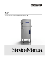
STERO'S SGW GLASS WASHER
(FRONT & SIDE PANELS NOT SHOWN)
PAGE 11

SGW GLASS WASHER MAIN ASSEMBLY

MAIN ASSEMBLY - PARTS LIST
ITEM DESCRIPTION REMARKS PART NO.
1 PANEL FRONT
B10-1351
2 PANEL SIDE - RIGHT HAND OPTIONAL EQUIP B10-1352
3 PANEL SIDE - LEFT HAND OPTIONAL EQUIP B10-1353
4 FRAME
B10-1354
5 FOOT - ADJUSTABLE
P60-1101
6 WASH TANK COMPLETE
B10-1355
7 HOOD - SINGLE DOOR SLANTED
B10-1356
8 DOOR - SLANTED SINGLE
B10-1357
9 DRAIN - SUMP TANK
B10-1358
10 DRAIN - SUMP STRAINER PAN
B10-1359
11 PUMP INTAKE SCREEN
A10-1415
12 TEMPERATURE GAUGE BRACKET
B10-1444
13 TEMPERATURE GAUGE
P65-1135
14 TEMPERATURE GAUGE BACK-UP RING
A10-1445
15 LOCKNUT S.S. 1/2"
A10-1446
16 DRAIN TANK BRACKETS
A10-1447
17 HOSE
P57-1137
18 CLAMP
P60-1138
19 DOOR HANDLE
B59-1448
20 LABEL – “SCRAP CATCHMENT STRAINER PAN" A69-1450
21
LABEL - " WARNING DISCONNECT ALL POWER"
A69-1449
22 LABEL - "DOOR SAFETY SWITCH"
A69-1451
23 LABEL - "HAVE FRONT PANELS IN PLACE" A69-1452
24 LABEL - "OPERATING INSTRUCTIONS'
A69-1453
25 TRACK GUIDES
A10-1500
13

PRESSURE SPRAY MANIFOLDS, UPPER AND LOWER ASSEMBLIES
INCLUDING PUMP & PRESSURE SWITCH.
PAGE 14

PRESSURE SPRAY MANIFOLDS UPPER & LOWER
PUMP
&
PRESSURE SWITCH PARTS LIST
ITEM DESCRIPTION REMARKS PART NO.
1 PUMP SUCTION TUBE ASSEMBLY
A10-1361
2 GASKET PUMP SUCTION TUBE FLANGE 2 REQUIRED A57-1341
3 LOCKNUT, CONDUIT - 1 1/4"
P52-1031
4 SEAL RING - 1 1/4"
P52-1032
5 SEAL RING - 1"
P52-1033
6 WASHER BACK-UP FOR SEAL RING
A10-1362
7 LOCKNUT, CONDUIT - 1"
P52-1034
8 MANIFOLD TEE BOTTOM BOX ASSEMBLY B10-1363
9 GASKET MANIFOLD TEE BOX
A57-1365
10 WASH ARM PIVOT PIN ASSEMBLY
A10-1366
11 WASH ARM
C10-1367
12 BUSHING - WASH ARM
A10-1735
13 COVER - WASH ARM TOP
A10-1339
14 END CAPS - WASH ARM
A10-4131
15 O RING
P57-2031
16 RISER TUBE ASSEMBLY
A10-1368
17 SPRAY MANIFOLD ASSEMBLY UPPER
B10-1371
18 SPRAY JETS 4 REQUIRED B10-1062
19 GASKET - RISER TO MANIFOLD
A57-1373
20 PRESSURE SWITCH
P54-1103
21 ¼" TUBE x 1/8" MIP ST. FITTING
P68-1507
22 1/4" TUBE x 1/4" MIP 90º ELBOW
P68-1506
23 1/2" x CLOSE NIPPLE
P52-1244
24 WIRE CORD - 16/3
P45-2180
25 SLEEVE, CONDUIT - 1/2"
P52-1039
26 LOCKNUT. CONDUIT - 1/2" 4 REQUIRED P52-1035
27 BUSHING, INSULATING - 1/2"
P52-1043
28 STRAIN RELIEF 90º ELBOW
P52-1059
29 SEAL RING - 1/2"
P52-1038
30 TUBING - 1/4" OD COPPER
P51-1671
15

PAGE 16
SGW PRICE PUMP ASSEMBLY
PAGE 16

PRICE PUMP ASSEMBLY
ITEM DESCRIPTION REMARKS PART NO.
1 MOTOR ELECTRIC 1/3 HP 115/230V
P41-1056
2 PUMP UNIT COMPLETE
P41-1026
3 SEAL RING 1 1/4"
P52-1032
4 LOCKNUT CONDUIT 1 1/4"
P52-1031
5 PUMP SUCTION TUBE ASSEMBLY
A10-1361
6 SEAL RING 1"
P52-1033
7 WASHER BACK-UP FOR SEAL RING
A10-1362
8 LOCKNUT - CONDUIT V
P52-1034
9 MANIFOLD TEE BOTTOM BOX ASSEMBLY
B10-1363
10 PUMP COUPLING
P41-1029
11 SHAFT SEAL
P57-1030
12 IMPELLER
A41-1294
13 GASKET
B57-1334
14 1/4" TUBE x 1/8" MIP 90º ELBOW
P68-1508
17

PAGE 18

GOULD PUMP / MOTOR ASSEMBLY
1/3
HP 115/230V
1
PHASE
ITEM DESCRIPTION REMARKS PART NO.
1 PUMP HOUSING (VOLUTE)
C10-3255
2 PUMP IMPELLER
P41-2452
3 PUMP SEAL
P57-2083
4 GASKET - FLANGE TO PUMP
A57-3287
5 PUMP SEAL HOUSING
P41-2082
6 MOTOR ONLY
B41-3256
7 COMPLETE ASSEMBLY
C10-3254
19

DOOR PIVOT & SPRING BALANCE
ASSEMBLIES
PAGE 20

DOOR PIVOT AND
SPRING BALANCE ASSEMBLY
ITEM DESCRIPTION REMARKS PART NO.
1 ANCHOR BRACKET, DOOR SPRING
A10-1374
2 DOOR SPRING
A60-1375
3 EYEBOLT 1/4-20 x 2 1/4" LONG
P67-1104
4 DOOR SPRING/SW ADJ BRKT ASSY
A10-2314
5 DOOR SWITCH BRACKET
A10-1380
6 DOOR SAFETY SWITCH N/O
B10-3273
7 DOOR PIVOT SUPPORT 2 REQUIRED A10-1383
8 DOOR BUSHING 2 REQUIRED P66-1062
9 3/16" CONDUIT CLAMP
A10-1348
21

MACHINE, DRAIN ASSEMBLY
PAGE 22
/