Page is loading ...

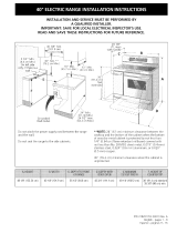
INSTALLATION AND SERVICE MUST BE PERFORMED BY
A QUALIFIED INSTALLER.
IMPORTANT: SAVE FOR LOCAL ELECTRICAL INSPECTOR'S USE.
READ AND SAVE THESE INSTRUCTIONS FOR FUTURE REFERENCE.
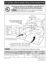
Do not pinch the power supply
cord between the range and
the wall.
Do not seal the range to the
side cabinets.
NOTE: 24" (61 cm)
minimum clearance
between the cooktop and
the bottom of the cabinet
when the bottom of wood
or metal cabinet is
protected by not less than
1/4" (0.64 cm) flame
retardant millboard covered
with not less than No. 28
MSG sheet metal, 0.015"
(0.4 mm) stainless steel,
0.024" (0.6 mm)
aluminum, or 0.020" (0.5
mm) copper.
30" (76.2 cm) minimum
clearance when the cabinet
is unprotected.
NOTE: Allow at least
19 ¼" (48.9 cm) clearance
for door depth when it is
open.
Shave Raised Edge
To Clear 30" (76.2
cm) Wide Cooktop
Rim.
1 1/2"Max.
(3.8 cm Max.)
Locate Cabinet Doors 1
(2.5 cm) Min. From Cutout
Opening
* Note: 29" (73.7 cm)
Wide Opening For
Overlapping Cooktop and
Built-In Look.
If Installing Models With
Optional Side Panels,
Cutout Area Including
Countertop Must Be At
Least 30" (76.2 cm) Wide.
1 1/2"
30" Min.
(76.2 cm) Min.
(76.2 cm) Min.**
18" Min.
(45.7 cm) Min.
Grounded Junction Box or Wall
Outlet Should Be Located 8" to
17" (20.3 - 43.2 cm) From Right
Cabinet and 2" to 4" (5.1-10.2
cm) From Floor
Min.
(61 cm) Min.
• Door Open,..
(see note) .......... /
A
r_ 22 718"_1
(58.1 cm)
ili! !i
Ol 1/8"
(45.7 cm
FRONT _ GRef'_
OF
CABINET
35 3/8"- 36 3/8"(90-92 cm) 30" (76.2 cm) 26 1/4"(66.7 cm) 29" (73.7 cm) 21 3/4" (55.2 cm) 36" (91.4 cm) standard
35%" (90cm)min.
G. Minimum cutout depth is increased to 24" (61 cm) with backguard. P/N318201603 (0201) Rev. B
English- pages 1-10
Espahol- p_tginas11-20

Important Notes to the Installer
1. Readall instructions contained in these installation
instructions before installing range.
2. Remove all packing material from the oven and the
drawer compartments before connecting the electrical
supply to the range.
3. Observe all governing codes and ordinances.
4. Besure to leavethese instructions with the consumer.
Important Note to the Consumer
Keep these instructions with your owner's guide for future
reference.
IMPORTANT SAFETY
INSTRUCTIONS
• Be sure your range is installed and grounded
properly by a qualified installer or service
technician.
• This range must be electrically grounded in
accordance with local codes or, in their absence,
with the National Electrical Code ANSI/NFPA No.
70--latest edition.
• The installation of appliances designed for
manufactured (mobile) home installation must conform
with Manufactured Home Construction and Safety
Standard, title 24CFR, part 3280 [Formerly the Federal
Standard for Mobile Home Construction and Safety,
title 24, Hun (part 280)] or when such standard is not
applicable, the Standard for Manufactured Home
Installation 1982 (Manufactured Home Sites,
Communities and Setups), ANSI Z225.1/NFPA 501A-
latest edition, or with local codes.
• Make sure the wall coverings around the range
can withstand the heat generated by the range.
• All ranges
can tip.
• Injury to
personscould
result.
• Install anti-tip
device
packed with
range.
IV!'W'-_It_II_[cl To reduce
the risk of tipping of the
range, the range must be
secured by properly
installed anti-tip bracket
(s)provided with the
range. To check if the
bracket (s)is installed
properly, grasp the top
rear edge of the range
and carefully tilt it
forward to make sure the
range isanchored.
Before installing the range in an area covered
with linoleum or any other synthetic floor
covering, make sure the floor covering can
withstand heat at least 90°F above room
temperature without shrinking, warping or
discoloring. Do not install the range over carpeting
unless you place an insulating pad or sheet of 1/4"
thick plywood between the range and carpeting.
Never leave children alone or
unattended in the area where an appliance is in use.
As children grow, teach them the proper, safe use of all
appliances. Never leave the oven door open when the
range is unattended.
Stepping, leaning or sitting on the
door or drawer of this range can result in serious
injuries and can also cause damage to the range.
• Do not store items of interest to children in the
cabinets above the range. Children could be seriously
burned climbing on the range to reach items.
• To eliminate the need to reach over the surface
units, cabinet storage space above the units
should be avoided.
• Do not use the oven as a storage space. This
creates a potentially hazardous situation.
• Never use your range for warming or heating the
room. Prolonged use of the range without adequate
ventilation can be dangerous.
• Do not store or use gasoline or other flammable
vapors and liquids near this or any other
appliance. Explosions or fires could result.
• Reset all controls to the "off" position after using
a programmable timing operation.
FOR MODELS WITH SELF-CLEANFEATURE:
• Remove broiler pan, food and other utensils
before self-cleaning the oven. Wipe up excess
spillage. Follow the precleaning instructions in the Use
and Care Guide.
Power Supply Cord Kit
The user is responsible for connecting the power supply
cord to the connection block located behind the back
panel access cover.
This appliance may be connected by means of
permanent "hard wiring" (flexible armored or
nonmetallic shielded copper cable), or by means of a
power supply cord kit. Only a power supply cord kit rated
at 125/250 volts minimum, 40 amperes minimum and
marked for use with ranges shall be used. See chart
(next page) for cord kit connection opening size
information. Cord must have either 3 or 4 conductors.

Formobilehomes,newinstallations,recreational
vehicles,orareaswherelocalcodesdonotpermit
groundingthroughneutral,a4 conductorpowersupply
cordkitratedat125/250voltsminimum,40amperes
andmarkedforusewithrangesshouldbeused(see
Figure4).
Terminalsonendofwiresmustbeeitherclosedloopor
open-endspadelugswithupturnedends.Cordmust
havestrain-reliefclamp.
Seebelowfor3or4conductorwireconnection.
Range Connection Opening Size Chart
Refer to chart below for proper range connection opening size
and power supply cord kit ampere rating information. See serial
plate on range for kilowatt rating data.
See Serial Plate on Range
for KW Rating
120/240 Volts 120/208 Volts
8.8-16.5 Kw 7.9-12.5 Kw
16.6-22.5 Kw 12.6-18.5 Kw
Minimum
Cord kit
Ampere
Rating
40 Amp
50 Amp
Diameter (inches) of Range
Connection Opening
Direct
Cord Kit Connection
1-3/8 in. 1-1/8 in.
1-3/8 in. 1-3/8 in.
NOTE: Electric Slide-in Range isshipped from factory with
1-1/8" dia. hole asshown on figure 3. If a larger hole is
required, punch out the knockout.
Risk of fire or electrical shock exists if
an incorrect size range cord kit is used, the
Installation Instructions are not followed, or the
strain relief bracket is discarded.
Electrical Shock Hazard
Electrical ground is required on this appliance.
Do not connect to the electrical supply until
appliance is permanently grounded.
Disconnect power to the circuit breaker or fuse
box before making the electrical connection.
This appliance must be connected to a
grounded, metallic, permanent wiring system,
or a grounding connector should be connected
to the grounding terminal or wire lead on the
appliance.
Failure to do any of the above could result in a
fire, personal injury or electrical shock.
Three Conductor Wire Connection to Range
(The 3-conductor cord or cable must be replaced with a
4-conductor cord or cable where grounding through the
neutral conductor is prohibited in new installations,
mobile homes, recreational vehicles or in other areas
where local codes do not permit neutral grounding)
If local codes permit connection of the frame grounding
conductor to the neutral wire of the copper power supply
cord (see Figure 3).
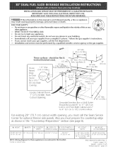
, Remove the 3 screws at the lower end of the rear
wire cover, then bend the lower end of the rear wire
cover (access cover) upward to expose range
terminal connection block (see Figure 2).
Figure 1
Do not loosen the nuts which secure
the factory-installed range wiring to terminal block
while connecting range. Electrical failure or loss of
electrical connection may occur.
Electrical Connection to the Range
This appliance is manufactured with the neutral terminal
connected to the frame.
BEND REAR WIRE COVER HERE
FORACCESSTOTERMINALBLOCK
Figure 2
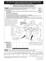
2. Remove the 3 loose nuts (after you remove the
rubber band) on the terminal block using 3/8" nut
driver or socket.
3. Connect the neutral of the copper power supply cord
to the center silver-colored terminal of the terminal
block, and connect the other wires to the outer
terminals. Match wires and terminals by color (red
wires connected to the right terminal, black wires
connected to the left terminal).
4. Replace the 3 nuts on the terminal block (see figure
3).
5. Lower the terminal cover and replace the 3 screws.

Silver colored Terminal
Block
Terminal
Wire
Terminal
Block
Black
wire
supplied by the user
must be installed at
this location
To 240 V
receptacle
Figure 3
1-1/8" Dia.
Direct
Connection
Hole. Punch
out knockout
for 1-3/8" Dia.
Cord Kit Hole
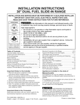
Four Conductor Wire Connection to Range
(mobile homes)
1. Remove the 3 screws at the lower end of the rear
wire cover, then raise the lower end of the rear wire
cover (access cover) upward to expose range
terminal connection block (see figure 2).
2. Remove the 3 loose nuts (after you remove the
rubber band) on the terminal block using a 3/8" nut
driver or socket.
3. Remove the ground strap from the terminal block
and from the appliance frame.
4. Connect the ground wire (green) of the copper
power supply cord to the frame of the appliance
with the ground screw, using the hole in the frame
where the ground strap was removed (see Figure 4).
5. Connect the neutral of the copper power supply cord
to the center silver-colored terminal of the terminal
block, and connect the other wires to the outer
terminals. Match wires and terminals by color (red
wires connected to the right terminal, black wires
connected to the left terminal).
6. Replace the 3 nuts on the terminal block (see figure
4).
7. Lower the terminal cover and replace the 3 screws.
Bla_
1-1/8" Dia.
Direct
Connection
Hole. Punch
out knockout
for 1-3/8" Dia.
Cord Kit Hole
A strainrelief
supplied by the user
must be installed at 240 V receptacle
this location
NOTE: Be sure to remove the supplied /<l
grounding strap
Figure 4
Direct Electrical Connection to the Circuit
Breaker, Fuse Box or Junction Box
If the appliance is connected directly to the circuit
breaker, fuse box or junction box, use flexible, armored
or nonmetallic sheathed copper cable (with grounding
wire). Supply a U.L. listed strain-relief at each end of the
cable. At the appliance end, the cable goes through the
Direct Connection Hole (see Figure 4) on the Cord
Mounting Plate. Wire sizes (copper wire only) and
connections must conform to the rating of the appliance.
Where local codes permit connecting the appliance-
grounding conductor to the neutral (white) wire
(see Figure 5):
(The 3-conductor cord or cable must be replaced with a
4-conductor cord or cable where grounding through the
neutral conductor is prohibited in new installations,
mobile homes, recreational vehicles or in other areas
where local codes do not permit neutral grounding)
.
2.
Disconnect the power supply.
In the circuit breaker, fuse box or junction box:
connect appliance and residence cable wires as
shown in figure 5.
4

White Wire
(Neutral)
Red
Cable from
Residence
Wires-
Cabinet Construction
To eliminate the risk of burns or fire by
reaching over heated surface units, do not have cabinet
storage space above the range. If there is cabinet
storage space above range, reduce risk by installing a
range hood that projects horizontally a minimum of 5"
(12.7 cm) beyond the bottom of the cabinet.
Box
White Wire
(Neutral)
Green U.L.-listed
(or Bare Copper) Conduit
Wire Cable from Connector
Range (or CSA listed)
Figure 5
3-Wire (Grounded Neutral) Electrical System
(Example: Junction Box)
Where local codes DO NOT permit connecting the
appliance-grounding conductor to the neutral
(white) wire, or if connecting to 4-wire electrical
system (see Figure 6):
1. Disconnect the power supply.
2. Separate the green (or bare copper) and white
appliance cable wires.
3. In the circuit breaker, fuse box or junction box:
connect appliance and residence cable wires as
shown in figure 6.
Cou ntertop Prepa ration
• The cooktop sides of the range fit over the cutout edge
of your countertop.
• If you have a square finish (flat) countertop, no
countertop preparation is required.
• Formed front-edged countertops must have molded
edge shaved flat 1/4" (0.64 cm) from each front corner
of opening.
• Tile countertops may need trim cut back 1/4" (0.64
cm) from each front corner and/or rounded edge
flattened.
width ,,f
30.00
_(76.2 cm)
Formed or tiled countertop
trimmed 1/4 (.064cm)
(.64 cm) back at front corners of
I countertop opening.
Cable from
Junction
Green Residence
(or Bare Copper) Box
Green
(or Bare Copper)
Wire
Cable from Conduit
Appliance Connector
(or CSA listed)
Figure 6 - 4-Wire Electrical System
(Example: Junction Box)
If the countertop opening width is greater than
the minimum cutout width, adjust the 1/4" (0.64
cm) dimension.
Countertop must be level. Place a level on the
countertop, first side to side, then front to back. If the
countertop is not level, the range will not be level. The
oven must be level for satisfactory baking results.
Cooktop sides of range fit over edges of countertop
opening.

Range Installation
When unpacking the range, do not
discard the 2 front shipping bolts, but screw them into
the holes at the front corners of the range; they will
function asthe front leveling legs. Discard the 2 other
bolts; they are not needed, and are installed on the
range for shipping purposes only. This appliance is
equipped with a new rear leveling system that allows
you to level the range after installation in cutout
opening.
Installation Without Side Panel(s)
1. The range cooktop overlaps the countertop at the
sides and the range rests on the floor. The cooktop is
30" (76.2 cm) wide.
2. Install base cabinets 29" (73.7 cm) apart. Make sure
they are plumb and level before attaching cooktop.
Shave raised countertop edge to clear 30" wide
range top rim.
3. Install cabinet doors 31 " (78.7 cm) min. apart so it
will not interfere with range door opening.
4. Cutout countertop exactly as shown on page 1.
5. A backguard kit can be ordered through Sears
Service Center.
For models equipped with Leveling Device:
6. When you unpack the range, the leveling devices
at rear are at the highest position they can be.
Make sure the front leveling legs are also at their
highest position.
7. _ Install the anti-tip bracket at this
point before placing the range at its final
position. Follow the installation instructions on
page 8 or on the anti-tip bracket template
supplied with the range.
8. Slide the range into the cutout opening.
9. Level the range (figure 7). The floor where the
range is to be installed must be level. Follow
the instructions under "Leveling the Range-
Models Equipped with Leveling Device"
For models equipped with Leveling Legs:
6. Adjust leveling legs so that the underside of the
cooktop issitting on the countertop.
7. Level the range. The floor where the range is
to be installed must be level. Follow the
instructions under "Leveling the Range-Models
Equipped with Leveling Legs"
5. Follow steps 6 to 9 "Installation Without Side
Panels" above.
Installation With Backguard
The cutout depth of 21 5/8" (55 cm) needs to be
increased to 24" (61 cm) when installing a backguard.
Leveling the Range - Models Equipped with
Leveling Device
Level the range after installation in the cutout
opening.
1. Open the range drawer and remove the two metallic
caps covering the 2 leveling screws. These leveling
screws control the height of the rear leg.
2. Adjust the appliance legs as follows until the
underside of the cooktop surface is sitting level on
the countertop (Figure 7).
a.To adjust the front legs, use a wrench on the leg
base and turn clockwise to lower or
counterclockwise to raise.
b.To adjust the rear legs, use a ratchet or a
nutdriver and turn the leveling screws
counterclockwise to lower or clockwise to raise.
Font
Leveling
Leg
LOWER
RAISE
Installation With Side Panel(s)
1. Install base cabinets 30 V8" (76.5 cm) mm. apart.
Make sure they are plumb and level.
2. Install cabinet doors 31 " (78.7 cm) min. apart so as
not to interfere with range door opening.
3. A backguard kit can be ordered through a Sears
Service Center.
4. An end panel kit can be ordered through a Sears
Service Center.
Figure 7
3. Check if the range is level by installing an oven rack
in the center of the oven and placing a level on the
rack (Figure 8).
4. Take 2 readings with the level placed diagonally in
one direction and then the other. Level the range, if
necessary, by adjusting the leveling legs.
6

Figure8
5. If the range cannot be level, contact a carpenter to
correct sagging or sloping floor.
6. Replace the metallic caps in position.
Leveling the Range - Models Equipped with
Leveling Legs
Level the range and set cooktop height before
installation in the cut-out opening.
1. Install an oven rack in the center of the oven.
2. Place a level on the rack (see figure 8). Take 2
readings with the level placed diagonally in one
direction and then the other. Level the range, if
necessary, by adjusting the 4 leg levelers with a
wrench (see Figure12).
3. Taking care to not damage the countertop, slide
range into cut-out opening and double check for
levelness. If the range is not level, pull unit out and
readjust leveling legs, or make sure floor is level.
Check Operation
Refer to the Use and Care Guide packaged with the
range for operating instructions and for care and
cleaning of your range.
Do not touch the elements. They may be
hot enough to cause burns.
Remove all packaging from the oven and the warmer
drawer (if equipped) before testing.
1. Operation of Surface Elements
Turn on each of the four surface elements and check to
see that they heat. Check the surface element indicator
light(s), if equipped.
2. Operation of Oven Elements
The oven isequipped with an electronic oven control. Each
of the functions hasbeen factory checked before shipping.
However, it issuggested that you verify the operation of
the electronic oven controls once more. Refer to the
Electronic Oven Control Guide for operation. Follow the
instructions for the Clock, Timer, Bake, Broil, Convection
(some models) and Clean functions.
Bake-After setting the oven to 350°F (177°C) for baking,
the lower element in the oven should become red.
Broil-When the oven isset to BROIL,the upper element
in the oven should become red.
Clean-When the oven isset for a self-cleaning cycle, the
upper element should become red during the preheat
portion of the cycle. After reaching the self-cleaning
temperature, the lower element will become red.
Convection {some models)-When the oven is set to
CONV. BAKE/ROASTat 350°F (177°C), the convection
element cycles on and off and the convection fan turns.
The convection fan will stop turning when the oven door
isopened during convection baking or roasting.
Warmer Drawer {some models)-Set the control knob
to HI and check to see the drawer is heating.
When All Hookups are Complete
Make sure all controls are left in the OFFposition.
Model and Serial Number Location
The serial plate is located on the oven front frame
behind the oven door (some models) or behind the
drawer (some models).
When ordering parts for or making inquiries about your
range, always be sure to include the model and serial
numbers and a lot number or letter from the serial plate
on your range.
Before You Call for Service
Read the Avoid Service Checklist and operating
instructions in your Use and Care Guide. It may save you
time and expense. The list includes common occurrences
that are not the result of defective workmanship or
materials in this appliance.
Refer to the warranty and service information in your Use
and Care Guide for Sears phone number and address.
Pleasecall or write if you have inquiries about your
range product and/or need to order parts.

Anti-Tip Brackets Installation Instructions-
Models Equipped with Leveling Device
To reduce the risk of tipping of the range,
the range must be secured to the floor by properly installed
anti-tip bracket and screws packed with the range. Those
parts are located in the oven. Failure to install the anti-tip
bracket will allow the range to tip over if excessive weight
is placed on an open door or if a child climbs upon it.
Serious injury might result from spilled hot liquids or from
the range itself.
Follow the instructions below to install the anti-tip
brackets.
If range isever moved to a different location, the anti-tip
brackets must also be moved and installed with the
range.
Tools Required:
Adjustable Wrench
Ratchet
Drill & 1/8" bit
5/16" Nutdriver
Level
The anti-tip bracket attaches to the floor at the back of
the range to hold range rear center leg. When fastening
bracket to the floor, be sure that screws do not
penetrate electrical wiring or plumbing. The screws
provided will work in either wood or concrete.
1. Draw a line on the floor (in front of the cutout)
aligned with the front of the cabinet (not with the
toe plate).
2. Unfold paper template and place it flat on the floor
with the front and side edges positioned exactly on
the cabinet line you just drew before. (Use the
diagram below to locate brackets if template is not
available. (figure 9))
3. Mark on the floor the location of the 4 mounting
holes shown on the template. For easier installation,
3/16" diameter pilot holes 1/2" deep can be drilled
into the floor.
4. Remove template and place bracket on floor. Line
up holes in bracket with marks on floor and attach
with 4 screws provided. Bracket must be secured to
solid floor (figure 10). If attaching to concrete floor,
first drill 3/16" dia. pilot holes using a masonry drill
bit.
5. Be sure the 4 leveling legs are at the highest position
they can be.
6. Slide range into place making sure rear center leg is
trapped by the anti-tip bracket (figure 9). Lower the
range by adjusting the 4 leveling legs until the
underside of the cooktop is sitting level on the
countertop. Refer to "Leveling the Range" section.
7. After installation, verify that the anti-tip bracket is
engaged by opening warmer drawer and looking
through openings in rear panel. If a storage drawer is
provided rather than a warmer drawer, open and
remove drawer and check to make sure the anti-tip
bracket is engaged.
Screws
Figure 10
RearCenterLeg
Figure 9
BACK
8

Anti-Tip Brackets Installation Instructions -
Models Equipped with Leveling legs
To reduce the risk of tipping of the range,
the range must be secured to the floor by properly
installed anti-tip brackets and screws packed with the
range. Those parts are located in a plastic bag in the
oven. Failure to install the anti-tip brackets will allow the
range to tip over if excessive weight is placed on an
open door or if a child climbs upon it. Serious injury
might result from spilled hot liquids or from the range
itself.
Follow the instructions below to install the anti-tip
brackets.
If range is ever moved to a different location, the anti-tip
brackets must also be moved and installed with the
range. To check for proper installation, see step 5.
Tools Required:
5116" Nutdriver or Flat Head Screwdriver
Adjustable Wrench
Electric Drill
3/16" Diameter Drill Bit
3/16" Diameter Masonry Drill Bit (if installing in
concrete)
1. Unfold paper template and place it flat on the floor
with the back and side edges positioned exactly
where the back and sides of range will be located
when installed. (Use the diagram below to locate
brackets if template is not available.)
2. Mark on the floor the location of the 4 mounting
holes shown on the template. For easier installation,
3/16" (0.5 cm) diameter pilot holes 1/2" (1.3 cm)
deep can be drilled into the floor.
3. Remove template and place brackets on floor with
turned up flange to the front. Line up holes in
brackets with marks on floor and attach with 4
screws provided. Brackets must be secured to solid
floor. If attaching to concrete floor, first drill 3/16"
(0.5 cm) dia. pilot holes using a masonry drill bit.
4. Level range if necessary, by adjusting 4 leg levelers
with wrench. (See Figure 12 below.) A minimum
clearance of 1/8" (0.8 cm) is required between the
bottom of the range and the rear leg levelers to
allow room for the anti-tip brackets.
5. Slide range into place making sure rear legs are
trapped by ends of brackets. Range may need to be
shifted slightly to one side as it is being pushed back
to allow rear legs to align with brackets. You may
also grasp the top rear edge of the range and
carefully attempt to tilt it forward to make sure
range is properly anchored.
Brackets attach to the floor at the back of the range to
hold both rear leg levelers. When fastening to the floor,
be sure that screws do not penetrate electrical wiring or
plumbing. The screws provided will work in either wood
or concrete.
i
BackEdgeof _--_ Anti-Tip Bracket
Rangeor RearWall
\. 3A"Typ.
I/2"(1.3 cm) ..-"_"'--._j
(I
_ 9
cm)
Typ.
i .- .... / 9 3A" "_.. (49.5 cm) 281/8"/
i .-'"_ _--_ (24.8 cm) /.
i.--" <_" - -Y "-...(71.4 cm)
""--. /_ _ / (Rearwidth of range
""-./. _with body sides)
Anti-Tip Bracket--/'''''- _
Figure 11
Back
Figure 12
9

Notes
10

LA INSTALACION Y EL SERVICIO DEBEN SER EFECTUADOS POR
UN INSTALADOR CALIFICADO.
IMPORTANTE: GUARDE ESTAS INSTRUCCIONES PARA USO DEL
INSPECTOR LOCAL DE ELECTRICIDAD.
LEA Y GUARDE ESTAS INSTRUCCIONES PARA REFERENCIA FUTURA.
No pellizque el cord6n el0ctrico
entre la estufa y la pared.
No selle la estufa a los armarios
de lado.
** NOTA: Un espacio minimo
de 24" (61 cm) entre la
superficie de la estufa y el
fondo del armario cuando el
fondo del armario de
madera o metal est_
protegido por no menos de
1/4" (0.64 cm) de madera
resistente al fuego cubierta
por una I_mina met_lica de
MSG, n0mero 28, 0.015"
(0.4 mm) de acero
inoxidable, 0.024" (0.6 mm)
aluminio, 6 0.020" (0.5
mm) de cobre.
Un espacio minimo de 30"
(76.2 cm) cuando el armario
no est_ protegido.
NOTA: Deje por los 19 ¼"
(48.9 cm) de espacio libre
para la profundidad de la
puerta cuando esta abierta.
Lije la parte elevade del borde
para obtener las 30" (76.2 cm)
de ancho del reborde de la
plancha de cocinar.
Localise las puertas
del armario 1" (2.5
cm) min. del hueco de
la abertura.
* Nora: 29" (73.7
cm) Anchura de la
abertura para plancha
traslapadala y
apariencia encerrada.
Para la instalaci6n de modelos
con paneles laterales
opci6nales, el _rea del hueco
incluyendo el armario dbe de
estar 30" (76.2 cm) de anchura
minimo.
1 1/2"
cm)
La caja de empalmes o el enchufe
de conexi6n con la tierra deberia
situarse de 8" a 17" (20.3 - 43.2
cm) del armario derecho y de 2" a
4" (5.1-10.2 cm) del suelo.
Min.
(61 cm) Min.
• Puerta abierta
(vea la nota)
A
22 7/8" "1
(58.1 cm)
Ol 1/8" d
(45.7 cm
PARTE _ G
DELANTERA Ref.
DEL
ARMARIO
353/8"- 363/8"(90-92cm) 30"(76.2cm) 26 1/4" (66.7cm) 29"(73.7cm) 21 3/4"(55.2cm) 36"(91.4cm)standard
353/8"(90cm)min.
G. La profundidad minima de recortadoseaumenta a 24" (61 cm) con el usode un protector trasero.
P/N 318201603 (0201) Rev. B
English - pages 1-10
Espahol - p_tginas 11-20

Notas importantes para el instalador
1. Leatodas las instrucciones antes de instalar la cocina.
2. Retire todo material de empaquetado del horno y de la
gaveta de entibiado antes de conectar el suministro
el_ctrico a la cocina.
3. Observe todo c6digo o reglamento.
4. Aseg0rese de dejar estas instrucciones con el consumidor
Nota importante para el consumidor
Mantenga estas instrucciones con el manual del usuario
para futuras referencias.
INSTRUCIONES DE
SEGURIDAD
IMPORTANTES
• Aseg_rese que su cocina est_ instalada y
conectada adecuadamente a tierra por un
instalador calificado o un tdcnico de servicio.
• Esta cocina debe ser conectada a tierra
eldctricamente de acuerdo con los codigos
locales, o de no existir, con la National Electrical
Code ANSI/NFPA No.70- t_ltima edici6n.
• La instalaci6n de el_ctrodom_sticos destinados para
casas (movibles) deben conformarse con la
Manufactured Home Construction and Safety
Standard, t[tulo 24CFR, parte 3280 [antiguamente la
Federal Standard for Mobile Home Construction and
Safety, t[tulo 24, HUD (parte 280)] o cuando este
c6digo no se aplica, la Standard for Manufactured
Home Installation 1982 (Manufactured Home sites,
communities and setups) ; ANSIZ225.1/NFPA 501A-
01tima edici6n o con c6digos locales.
• Aseg_rese que el empapelado de pared alrededor
de la cocina pueda resistir el calor generado por
la cocina.
• Antes de instalar la cocina en una &rea cubierta
de linoleo o cualquier otro revestidor de piso
sint_tico, aseg_rese que _ste pueda resistir al
@
[llrIy,_1llvJ :1 : l / :1_[_ V,_|
Todaslas
cocinas
pueden
inclinarse.
Estopuede
provocar
lesiones
personales
Instaleel
dispositivo
anti-inclinaci6n
que vienecon
lacocina.
rl v_.1,_,_=:1,=,,[_F_.IPara
reducirel riesgode
inclinaci6nde la cocina,
esta debe estarajustada
correctamentecon las
fijaciones anti inclinaci6n
quevienencon la cocina.
Paraverificarsi lasfijaciones
estan instaladas
adecuadamente,agarre la
partesuperior del borde
posteriorde la cocinay
inclinelahaciaadelante
cuidadosamentepara
asegurarque lacocinaesta
sujetada.
menos 90°F sobre la temperatura de la pieza sin
encogerse, ladearse o descolorisarse. No instale la
cocina encima de una alfombra a menos que coloque
una placa de aislamineto o una plancha de 1/4" de
madera entre la cocina y el alfombrado.
Nunca deje a los nifios solos o sin
cuidado en el area donde el el_ctrodom_stico etb en
uso. A medida que los nihos crezcan, ens_heles el uso
adecuado de los el_ctrodom_sticos.Nunca deje la puerta
del horno abierta cuando la cocina est_ sin supervisi6n.
Pisar, apoyarse o sentarse en las
puertas o los cajones de la cocina pueden causar
graves herridas y tambi_n dafiar la cocina.
• No coloque cosas que atraigan a los ni_os sobre
los gabinetes encima de la cocina. Los ni_os
podr[an sufrir quemaduras tratando de alcanzarlos.
• Para eliminar la necesidad de ir a buscar algo por
encima de los quemadores, no coloque gabinetes
por encima de _stos.
• No use el horno como espacio de
almacenamiento. Esto crea una situaci6n muy
peligrosa.
• Nunca use su cocina para calentar la pieza. El uso
prolongado de la cocina sin ventilaci6n adecuada
puede ser peligroso.
• No guarde o use gasolina u otros vapores
inflamables y liquidos cerca de _ste o cualquier
otro el_ctrodom_stico. Esto podr[a causar una
explosi6n o un incendio.
• Vuelva a programar todos los controles a la
posici6n "off" (apagado) despu_s de haber
utilizado el conteo contador autombtico.
PARA LOS MODELOS CON AUTO-LIMPIEZA:
• Retire el rostisador, la comida y otros utensilios
antes de auto-limpiar el horno. Limpie todo exceso
de derrames. Siga las instrucciones para la pre-
limpieza en el Manual del usuario.
Estuche de cable del suministro el_ctrico
Elutilisador es responsable de la conexi6n del cable del
suministro el_ctrico al bloque de conexi6n situado detr_is
del panel de acceso.
Esteel_ctrodom_stico puede serconectado por medio de
una "conexi6n directa" de cables permanentes (cable
blindado flexible o no met_ilico recubierto de cobre), o por
medio de un ensamblaje de cord6n de suministro el_ctrico.
Solamente un ensamblaje de cord6n de suministro el_ctrico
con regimen de 125/250 voltios m[nimo, 40 amperios
m[nimo y marcado para uso con cocinas debe ser utilizado.
Vea la tabla (p_igina proxima) para informaci6n sobre el
tama_o de abertura de laconexi6n del ensamblaje de
cord6n. Elcord6n debe de tener 3 o 4 conductores.
12

Para lascasassobre ruedas, las nuevas instalaciones, en los
veh[culos de recreaciOn o en las_ireasdonde los cOdigos
locales no permiten la conexiOn del conductor a tierra al
neutro, un ensamblaje de suministro el_ctrico de 4
conductores para estufas, clasificado a 125/250 voltios
m[nimo, 40 amperios m[nimo, debe de ser utilizado (ver la
figura 4).
Losbornes a la extremidad de los alambres deben ser a
curvas cerradas o con extremidades de lenguetas en forma
de U abiertas y curvadas. El cordon debe detener una
abrazadera releva de anclaje.
Ver la tabla de arriba para conexiOn de alambres de 3 o 4
conductores.
Tabla de tamafio de abertura de conexibn de cocina
Referirse a la tabla de arriba para el tamafio de abertura de
connexion de cocina adecuada, y la informaci6n sobre el regimen
de amperios del ensamblaje de cordon de suministro electrico.
Vea la placa de serie de la
cocina para informaciOn
sobre el regimen de
kilovatio.
120/240 Volts 120/208 Volts
8.8-16.5 Kw 7.9-12.5 Kw 40 Amp
16.6-22.5 Kw 12.6-18.5 Kw 50 Amp
Minimo
regimen de
amperios de
ensamblaje
del cord6n
Diametro (pulgadas) de
abierta de conexi6n de
cocina.
Ensemblaje Connect.
del cord6n directa
1-3/8 pulg 1-1/8 pulg
1-3/8 pulg 1-3/8 pulg
Nora: La cocina corrediza el_trica viene de fabrica con
un agujero de diametro 1-1/8" come se muestra en la
figura 3. Si un agujero mas largo est,1necesario retire la
arandela pre-cortada
El riesgo de fuego o de choque
el_ctrico puede aparecer si usa el tamafio de cable
incorrecto, si las instrucciones de instalacibn no son
seguidas o si retira la abrazadera de releva.
Figura 1
No desajuste las tuercas que
aseguran la conexibn de la cocina al bloque
terminal cuando est_ instalandola. El corte o la
perdida de corriente el_ctrica puede ocurrir.
13
Conexibn el_ctrica a la cocina.
Esteel_ctrodom_stico est,1fabricado con el borne neutro
conectado al armaz6n.
r ! , vA=1;i / =1[e.]v,_11
Peligro de choque el_ctrico
• La conexibn a tierra es requerida para este
el_ctrodom_stico.
• No conecte al suministro el_ctrico hasta que el
el_ctrodom_stico este conectado a tierra de
manera permanente.
= Desconecte el suministro el_ctrico hacia la caja
de empalmes antes de hacer la conexibn
el_ctrica.
= Este el_ctrodom_stico debe ser conectado a un
sistema de alambres permanentes, met&licos,
conectados a tierra o una puesta a tierra debe ser
conectada al terminal de tierra o un emplonbado
al el_ctrodom_stico.
Elno seguir ninguna deestas instruccionespodria
causarfuego, heridas personalesochoques electricos.
Conexibn del cable a tres alambres la cocina.
(Un cord6n flexible o cable de 3 conductores debe de ser
reemplazado con un cord6n flexible o cable de 4 conducto-
resdonde la conexi6n del conductor a tierra al neutro esta
prohibida en las nuevas instalaciones, lascasassobre
ruedas, los vehiculos de recreaci6n o otras _ireasdonde los
c6digos locales no permiten la conexi6n a tierra al neutro.)
Si los c6digos locales permiten la conexi6n del conductor a
tierra del armaz6n al alambre neutral del cable de bronze
del suministro el_ctrico.(vea figura 3)
1. Retire los 3 tornillos de la parte baja de la cubierta
del cable trasero (cubierta
de acceso), luego levante
la cubierta hacia arriba
para tener acceso al
bloque de conexi6n del
borne terminal. (vea
figura 2)
2. Retire las 3 tuercas
desajustadas (luego de Inclineaquila
haber retirado la banda cubierta del alambre
de caucho) en el bloque trasero para tener acceso
terminal con destornillador al acoplamiento electrico
de tuercas o un casquillo Figura 2
adaptador de 3/8".
3. Conecte la parte neutral del cable de bronze de
suministro el_ctrico al terminal plateado que se
encuentra al centro del bloque terminal y, conecte
los otros alambres a los terminales externos. Aparee
los alambres y los terminales seg0n el color
(alambres rojos conectados al terminal derecho,
alambres negros conactados al terminal izquierdo).
4. Repone las 3 tuercas desajustadas en el bloque
terminal (vea figura 3).
5. Baje la cubierta del terminal y vuelva al colocar los 3
tornillos.

_e terminal
plata
Bloque terminal
>lata
Alambre
Rojo
Alambre
Negro
Una arazadera
de releva provista debe de estar
instalada a est_ ubicaci6n
Hacia el 240 V
recept_culo
Figura 3
/8" Dia.
Agujero de la
conexi6n directa.
Retira la arandela
pre-cortada para
1-318" Dia. Agujero
Conexibn del cable de cuatro conductores a la cocina.
(casas movibles)
1. Retire los 3 tornillos de la parte baja de la cubierta
del cable trasero, luego levante la cubierta hacia
arriba para tener acceso (cubierta de acceso) al
bloque de conexi6n del borne terminal.
2. Retire las 3 tuercas desajustadas (luego de haber
retirado la banda de caucho) en el bloque terminal
con destornillador de tuercas o un casquillo
adaptador de 3/8".
3. Retire la correa de la base del bloque terminal y del
armaz6n del el_ctrodom_stico. Retenga el tornillo de
la base.
4. Conecte el alambre de tierra (verde) del cable de
bronze del suminitro el_ctrico al armaz6n del
el_ctrodom_stico con el tornillo de la base, usando
el hoyo del armaz6n por donde retir6 la correa de la
base (vea figura 4)
5. Conecte el alambre neutral (blanco) del cable de
cobre del suministro el_ctrico al terminal plateado
del centro del bloque terminal y, conecte los otros
alambres a los terminales externos.
6. Repone las 3 tuercas desajustadas en el bloque
terminal (vea figura 4).
7. Baje la cubierta del terminal y vuelva al colocar los 3
tornillos.
Alambre
Negro j_
1-1/8" Dia.
Agujero de la
conexi6n
directa.Retira
la arandela
pre-cortada
para 1-3/8" Dia.
Agujero
Una arazadera
de releva provista
debe de estar Hacia el 240 V recept_culo
instalada a est_
ubicaci6n
NOYA: Asegurese de quitar •
la banda de puesta a tierra provista.
Figura 4
Conexibn el_ctrica directa al cortacircuito, a
la caja de fusibles 0 la caja de empalmes
si el aparato est_ conectado directamente al cortacircuito,
a la caja de fusibles o a la caja de empalmes, use un cable
blindado flexible o no met_lico recubierto de cobre (con
alambre a tierra). Provee una abrazadera releva de anclaje
homologo UL a cada extremidad del cable. A la
extremidad del el_ctrodom_stico, el cable pase a trav_s del
agujero de laconexi6n directa (ver figura 4) en el cord6n
de la plata de montaje. Eltamaho de los alambres
(alambre de cobre solamente) y lasconexiones deben
estar conforme al regimen del el_ctrodom_stico.
Donde los cbdigos locales permitan conectar el
conductor de puesta a tierra del el_ctrodom_stico al
neutral (blanco) (yea figura 5):
(Un cord6n flexible o cable de 3 conductores debe de ser
reemplazado con un cord6n flexible o cable de 4 conducto-
resdonde la conexi6n del conductor a tierra al neutro esta
prohibida en las nuevas instalaciones, lascasassobre
ruedas, los vehiculos de recreaci6n o otras _reas donde los
c6digos locales no permiten la conexi6n a tierra al neutro.)
1. Desconecte el suministroel_ctrico.
2. Enel cortacircuito, la caja de fusibles o la caja de
empalmes
a) Conecte el alambre verde (o cobre desnudo), el
alambre blanco del cable del el_ctrodom_stico y el
alambre neutral (blanco) juntos.
b) Conecte los dos alambres negros juntos.
c) Conecte los dos alambres rojos juntos.
14

Alambre
Blanco
(Neutro)
Alambres_
rojo
Cable de la fuente
de alimentacibn
negros
Caja de
empalmes
Alambre
Blanco
Alambres (Neutro)
desnudos Conductor de
unibn listado-UL
o verdes Cable de la (listado-CSA)
estufa
Figura 5 - Sistema el_ctrico (ejemplo: caja de
empalmes) de 3 alambres (a tierra neutral)
Donde los cbdigos locales NO permitan conectar el
conductor de puesta a tierra del el_ctrodom_stico al
neutral (blanco), o si est& conectado con un sistema a
4 alambres (vea figura 6):
1. Desconecte el suministroel_ctrico
2. Separe el alambre verde (o cobre desnudo) y el
alambre blanco del electrodom_stico.
3. En el cortacircuito, la caja de fusibles o la caja de
empalmes.
a. Conecte el alambre blanco del cable del
el_ctrodom_stico al alambre neutral (blanco).
b. Conecte los 2 alambres negrosjuntos.
c. Conecte los 2 alambres rojosjuntos.
d. Conecte el alambre verde (o de cobre desnudo) de
la puesta a tierra del alambre al alambre de
puesta a tierra del cortacircuito, de la caja de
fusibles o de la caja de empalmes.
Alambre Cable de la fuente Caja de
desnudo o de alimentaci6n empalmes
verde Alambre
Alambres
,lojos
(Neutro)
Alambres
negros
Construcci6n del armario
rl1.J..t:[ef__lL,.][,]_l Para eliminar el riesgo de quemaduras o
de fuego tratando de alcanzar algo por encima de las
zonas calientes, evite de colocar art[culos sobre la
cocina. Si cree necesitar este espacio, el riesgo puede
disminu[r si instala un sombrerete que proteja
horizontalmente un m[nimo de 5" (12.7cm) sobre la
base del armario.
Preparacibn del mostrador
• Lasextremidades de la cocina sobrepasan el borde de
su mostrador.
Si tiene un mostrador con las extremidades
cuadradas (planas), no se necesita ninguna
preparaci6n del mostrador.
El reborde de frente de mostradores moldeados
deben tener bordes moldeados a 1/4" (0,64cm) a
partir de cada extremidad de la apertura.
los mostradores enazulejos deber_n necesitar un
recorte de 1/4" (0.64cm) a partit de cada extremidad
y/o un borde redondeado aplanado.
1/4"
(.64 cm)
Anch
ueco min. 30.010,,_
76.2 cm)
ostrador moldeado o enazulejo
ecortado 1/4" (.064 cm) hada
trots en las esquinas de frente de la
I abertura del mostrador.
Si el ancho de la abertura del mostrador es m&s
grande que el ancho del torte minimal, ajuste a las
dimensiones como para el 1/4" (0.64).
El mostrador deber ser nivelado. Coloque un
nivelador sobre el mostrador, primero de lado a lado y
luego del frente hacia atr_is. Si el mostrador no est,1
nivelado, la cocina no estar_i nivelada. El horno debe
ser nivelado para tenet resultados satisfactorios al
hornear. Las extremidades de la plancha de la cocinar
sobrepasan los bordes de la abertura del mostrador.
Alambres
desnudos o
verdes
Cable de la
estufa
Alambre
Blanco
(Neutro)
de
unibn listado-UL
(o listado-CSA)
Figura 6 - Sistema el_ctrico de 4 alambres
(ejemplo caja de empalme)
15

Instalaci6n de la cocina.
Cuando desempaque la cocina, no
deseche los 2 pernos que vienen con el envfo. Estos son
colocados en la parte trasera de la unidad y sirven para
levantar y nivelar la cocina. Deseche los 2 otros pernos,
estos son necesarios para el envfo unicamente. Este
aparato esta equipado con un nuevo sistema que le
permite de nivelarlo despu_s que Io haya instalado en el
corte.
Instalacibn sin panel(es) lateral(es).
1. La plancha de cocinar se sobrepone por encima del
mostrador con sus extremidades y la cocina reposa
sobre el suelo. La plancha de cocinar es 30" (76,2
cm) de ancho.
2. Instale la base de los armarios a 29" (73.7 cm) de
espacio entre elias. Aseg0rese que estos esten
verticales y alineados antes de instalar la plancha de
cocinar. Lije el borde del mostrador para obtener las
30" en la parte superior del mostrador.
3. Instale las puertas del armario a 31 " (78,7 cm) de
espacio entre elias para que no interfieran con la
abertura de la puerta de la cocina.
4. Corte el mostrador exactamente como en la p_gina
1.
5. Puede pedir un juego de repuesto con su
representante.
Para los modelos equipado con un sistema de
dispositivo de nivelaci6n:
6. Cuando desempaque la cocina, el dispositivo
trasero para nivelarla se encuentra al m_s alto
nivel al cual puede Ilegar. Aseg0rese que las
patas delanteras esten tambi_n al m_s alto nivel.
7. Instale el soporte anti-inclinaci6n de acuerdo alas
instrucciones del patr6n anti-inclinaci6n ( si no Io
tiene vea la p_gina 8).
8. Deslize la cocina en el corte del mostrador.
9. Nivele la cocina. El piso donde se instala la
cocina debe estar nivelado. Siga las
instrucciones "nivelaci6n de la estufa- modelos
equipado con un sistema de dispositivo de
nivelaci6n ".
Para los modelos equipado con las patas
niveladoras:
6. Ajuste alas piernas de nivelaci6n de manera que
la parte de abajo de la plancha de cocinar est_
apoyada contra el mostrador.
7. Nivele la cocina. El piso donde se instala la
cocina debe estar nivelado. Siga las
instrucciones "nivelaci6n de la estufa- modelos
equipado con las patas niveladoras".
Instalaci6n con panel(es) lateral(es).
1. Instale la base de los armarios a 30 1/8" (76.5 cm)
de espacio entre elias. Aseg0rese que esten
verticales y niveladas.
2. Instale las puertas de los armarios a 31 " (78.7 cm)
de espacio entre elias para que no interfieran con la
abertura de la puerta de la cocina.
3. Puede pedir un juego de repuesto con su
representante.
4. Un juego de termino de panel puede ser pedido con
su representante.
5. Siga las etapas 6 a 9 indicadas anteriormente.
Instalaci6n con el repuesto.
La profundidad del corte de 21 5/8" (55 cm) necesita ser
aumentada a 24" (61 cm) cuando instala el repuesto.
Nivelaci6n de la estufa - Para los modelos
equipado con un sistema de dipositivo de
nivelaci6n.
Nivele la cocina despu_s de haberla instalado en la
abertura del mostrador.
1. Abra la gaveta y retire las dos tapas met_licas.
2. Baje el aparato, las 4 patas de nivelaci6n
alternadamente, hasta que la parte baja de la
superficie de cocci6n repose sobre el mostrador.
(figura 7)
LEVANTAR
¥ornillos de
nivelaci6n
Pata de
nivelaci6n
de frente
_ BAJAR
LEVANTAR_
Figura 7
3. Verifique si la cocina est_ nivelada colocando una
parrilla en el centro del horno y poniendo un nivel
sobre esta (figura 8).
4. Mida dos veces con el nivel en posici6n diagonal en
una direcci6n y luego en otra. Nivele la cocina si es
necesario ajustando las patas de nivelaci6n.
16

Figura8
5. Si al cocina no se nivela, aseg0rese que el piso este
nivelado.
6. Vuelva a colocar las tapas met_licas en su posici6n
original.
Nivelaci6n de la estufa - Para los modelos
equipado con las patas niveladoras.
Nivele la esufa y ajuste la altura de la estufa antes de
instalarla en la abertura.
1. Coloque una parilla del horno en el centro del horno.
2. Ponga un nivel sobre la parrilla (figura 8). Tome dos
lecturas con el nivel puesto diagonalmente en una
direcci6n y despu_s en la otra. Nivele la estufa, si es
necesario, ajustando las4 patas niveladoras con una
Ilave de tuercas.
3. Aseg0rese de no dahar al mostrador, deslice la estufa
dentro de la abertura del hueco y vuelva a verificar a la
nivelaci6n. Si la estufa no est_ nivelada, arranque el
electrodom_stico y vuelva a ajustar alas piernas o
asegu0rese que el suelo est_ nivelado.
Verificaci6n del funcionamiento.
Consulte el Manual del usuario que viene con la cocina
para las instrucciones de funcionamiento, el cuidado y la
limpieza de su cocina.
No toque los elementos. Pueden estar Io
suficientement calientes para causar quemaduras.
Retire todo embalaje del horno y la gaveta de entibiado (si
est_ equipado) antes deverificar el funcionamineto.
1. Utilizacibn de los elementos de superficie
Gire cada uno de los cuatro elementos de superficie y
verifique si est_n calentando. Verifique la luz o los luces del
indicador del elemento de superficie, si est_ equipado.
2. Utilizacibn de los elementos del horno.
Elhorno est_ equipado con un sistema electr6nico. Cada
funci6n ha sido verificada desde f_brica antes del env[o. Sin
embargo, se recomienda que verifique la operaci6n del
horno electr6nico una vez m_s. Consulte el Manual del
usuario. Siga las instrucciones para poner en
17
funcionamiento el reloj, el mcontador de tiempo, el homo,
el asador, el horno de convecci6n (en algunos modelos) y el
sistema de limpieza.
Hornear- Despu_s de poner el horno a 350°F(177°C) para
hornear, el elemento de la parte de bajo del horno debe
ponerse rojo.
Asar- Cuando se pone el horno para asar(BROIL),el
elemento de arriba del horno debe ponerse rojo.
Limpieza- Cuando el horno se pone en el ciclo para que
se limpie a si mismo, el elemento de arriba debe ponerse
rojo durante la parte de pre-calentamiento del ciclo de
limpieza. Despu_s de que Ilegue a la temperatura
adecuada de limpieza, el elemento de calentamiento
inferior seencender_ y debe ponerse rojo.
Horno de convecci6n (algunos modelos)- cuando el
homo se pone PARAHORNEARO ASAR CON
CONVECCl0N a 350 F(177 C), el elemento de convecci6n
alterne entre prendido y apagado. Elventilador de
convecci6n empezar_ a funcionar. El ventilador de
convecci6n se parar_ cuando se abra la puerta del horno
cuando seest_ horneando o asando con convecci6n.
Gaveta de entibiado (algunos modelos)- Ajuste la
perilla de control a HI y verifique si la gaveta est_
calentando.
Cuando todas las conexiones est&n
completadas.
Aseg0rese que todos loscontroles sedejan en la posici6n
de apagado (OFF).
Localizacibn del modelo y del nt_mero de
serie.
La placa con el n0mero de serie se puede encontrar en la
parte interior de la puerta del horno (algunos modelos) o
detr_s de la gaveta (algunos modelos).
Cuando pida componentes o desee obtener informaciones
sobre su cocina, aseg0rese de incluir el modelo y el n0mero
de serie o una letra o n0mero de la placa con el n0mero de
serie de su cocina.
Antes de Ilamar al servicio de reparaciones.
Lea la lista de verificaci6n Evitando Ilamados de servicio y
lasinstrucciones de operaci6n en el Manual del usuario.
Esto le puede ahorrar tiempo y dinero. La lista incluye
situaciones comunes que no son el resultado de fabricaci6n
o de piezas defectuosas.
Consulte la garantia y la informaci6n sobre el servicio en su
Manual del usuario para obtener nuestro n0mero de
tel_fono y direcci6n. Por favor Ilamenos o escriba si desea
informaci6n sobre su producto o si desea pedir
componentes.

Instrucciones de instalacibn de la fijacibn
anti-inclinacibn - Para los modelos equipado
con un sistema de dipositivo de nivelacibn.
Para reducir el riesgo de inclinaci6n de la
cocina, _sta debe ser asegurada hacia el piso con las
fijaciones de anti-inclinaci6n y lostornillos que vienen con
la cocina. Estoscomponentes seencuentran en el horno.
Si no instala las fijaciones, corre el riesgo que su cocina
pueda inclinarse si pone demasiado peso en ella o si un
niho sube sobre _sta. Esto podrfa ocasionar graves heridas
causadas por Ifquidos calientes o por la propia cocina.
Siga estas instrucciones para instalar lasfijaciones de anti-
inclinaci6n.
Si la cocina es trasladada a otro lugar, lasfijaciones de anti-
inclinaci6n deben tambi_n sertrasladados con la cocina.
Herramientas necesarias:
Llave de tuerca ajustable
Trinquete
Taladro el_ctrico con barrena de 1/8"
Aprietatuercas de 5/16"
Nivel
Abrazadera sujetada al suelo en la parte trasera de la
cocina para tener asida la pata ubicada en la parte poste-
rior de la cocina. AI fijarla al suelo, verificar que lostornillos
no atraviesen la instalaci6n el_ctrica o de fontaner[a. Los
tornillos provistos sirven para madera o concreto.
1. Marque en el suelo una I[nea (en frente al hueco)
d6nde Ilegue el armario (y no d6nde Ilegue el
contorno de la placa).
_0__o_P__°_°
ANTI
Armario
de cocina
I II Puertade
Contorno de armario
_ placa I
2. Despliegue el papel modelo y situarlo piano en el
suelo con los bordes de frente y laterales ubicados
exactamente sobre la Ifnea del armario que acabe
de dibujar. (Utilice el diagrama de abajo para situar
las fijaciones si no viene incluido en el modelo).
(figura 9).
3. Marque en el suelo la ubicaci6n de los cuatro orificios
de montaje que aparecen en el modelo. Para facilitar
la instalaci6n se pueden hacer en el suelo orificios
pilotos de 3/16" de di_metro de 1/2" de profundidad.
4. Retire el modelo y ubique la abrazadera en el suelo.
Alinee los orificios en la abrazadera con las marcas en
el suelo y ajuste con los cuatro tornillos provistos. La
abrazadora debe quedar fijada al suelo (figura 10)
s61ido. Si se fija al suelo concreto, primero haga
orificios pilotos de un di_metro de 3/16", utilizando
una barrena para concreto.
5. Aseg0rese que las4 patas de nivelaci6n est_n en la
m_s alta posici6n posible.
6. Deslice la cocina hacia su lugar aseg0rand6se que la
pata de centro trasera est_ completamente segura con
el soporte anti-inclinaci6n (figura 9). Baje la cocina
ajustando las 4 patas de nivelaci6n hasta que la
plancha de cocinar est_ apoyada en el mostrador.
Refiere a la "Nivelaci6n de la cocina" a la p_gina 6.
7. Despu_s de haber realizado la instalaci6n verifique
que la fijaci6n anti-inclinaci6n est_ empotrada
abriendo la gaveta de entibiado y mirando en la
abertura del panel trasero. Si una gaveta de
almacenamiento est_ povista en lugar de una gaveta
de entibiado, abra la gaveta, retire la gaveta y
verifique para asegurarse que est_ empotrada.
Tornillos de montaje J
de suelo
Figura 10
Pata posterior
DESLIZAR HACIA
DETR_
Figura 9
18

Instrucciones de instalacibn de la fijacibn
anti-inclinacibn - Para los modelos
equipado con las patas niveladoras.
Para reducir el riesgo de inclinaci6n de
la cocina, _sta debe ser asegurada hacia el piso con las
fijaciones de anti-inclinaci6n y los tornillos que vienen
con la cocina. Estos componentes se encuentran en el
horno. Si no instala las fijaciones, corre el riesgo que su
cocina pueda inclinarse si pone demasiado peso en ella
o si un niho sube sobre _sta. Esto podr[a ocasionar
graves heridas causadas por I[quidos calientes o por la
propia cocina.
Siga estas instrucciones para instalar lasfijaciones de anti-
inclinaci6n.
Si la cocina es trasladada a otro lugar, lasfijaciones de anti-
inclinaci6n deben tambi_n ser trasladados con la cocina.
Paracontrolar la instalaci6n apropiada, vea el paso n0mero
5.
Herramientas Necesarias:
Llave de tuerca de 5116" o destornillador para tornillos
de cabeza plana
Llave inglesa
Taladro el_ctrico
Broca de 3/16" de di_metro
Broca para taladro de mamposter[a de 3/16" de d[a.
(si se est_ instalando en concreto)
Lossoportes se fijan al suelo en la parte trasera de la
estufa para sujetar ambos niveladores de las patas
traseras. Cuando los est_ instalando al piso, aseg0rese de
que los tornillos no penetren el alambrado el_ctrico o
plomer[a. Lostornillos provistos pueden utilizarse en
madera o concreto.
1. Desdoble la plantilla de papel y col6quela plana en
el piso con los bordes laterales y el trasero colocados
exactamente donde la parte trasera y los lados de la
estufa ser_n colocados cuando sea instalada. (Use el
diagrama siguiente para ubicar los soportes si no se
dispone de la plantilla).
2. Marque en el piso la ubicaci6n de los 4 agujeros de
montaje como se muestra en la plantilla. Para
facilitar la instalaci6n, se pueden taladrar agujeros
piloto de 3/16" (0.5 cm) de dfa. y 1/2" (1.3 cm) de
profundidad en el piso.
3. Saque la plantilla y coloque los soportes en el piso
con la brida hacia arriba dirigida hacia el frente.
Alinee los agujeros en los soportes con las marcas en
el piso y sujete con los 4 tornillos provistos. Los
soportes deben estar asegurados al piso firme. Si se
va a instalar en piso de concreto, primero debe
taladrar agujeros gufa de 3/16" (0.5 cm) de di_metro
usando una broca para taladro de mamposter[a.
4. Nivele la estufa si es necesario ajustando las cuatro
patas niveladoras con una Ilave (Ver la Figura 12
abajo). Se requiere un espacio libre m[nimo de 1/8"
(0.8 cm) entre la parte inferior de la estufa y los
niveladores de las patas traseras para dejar espacio
para los soportes antivuelco.
5. Deslice la estufa a su lugar asegur_ndose de que las
patas traseras est_n sujetas por los extremos de los
soportes. La estufa puede necesitar ser movida
ligeramente a un lado cuando est_ siendo empujada
hacia atr_s para permitir que las patas se alineen con
los soportes. Usted tambi_n puede asir el borde
trasero de la cima de la estufa y cuidadosamente
intentar voltearla para asegurarse de que la estufa
sea adecuadamente anclada.
Borde de atras de la
)orte antivuelco
3A"Typ.
1/2"(1.3 ......f(1.9 cm)Typ.
c L
"::i_ __" .4 cm)
(Anchuratrasera de la
Soporte estufa con loslados)
antivuelco
!
Figura 11
Deslizar
hacia atras
19
Figura 12

Notas
2O
/