
1645 Lemonwood Dr.
Santa Paula, CA 93060 USA
Toll Free: (800) 253-2363
Tel: (805) 933-9970
bendpak.com
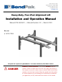
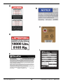
Heavy-Duty, Four-Post Alignment Lift
Installation and Operation Manual
Manual P/N 5900970 — Manual Revision C2 — March 2020
Model:
• HDS-18EA
Designed and engineered by BendPak Inc. in Southern California, USA. Made in China.
⚠
DANGER
Read the
entire
contents of this manual
before
using this
product. Failure to follow the instructions and safety precautions in
this manual can result in serious injury or death. Make sure all other
operators also read this manual. Keep the manual near the product
for future reference. By proceeding with installation and operation,
you agree that you fully understand the contents of this manual.

Manual. HDS-18EA Heavy-Duty, Four-Post Alignment Lift, Installation and Operation Manual, Manual Part
Number 5900970, Manual Revision C2, Released March 2020.
Copyright. Copyright © 2020 by BendPak Inc. All rights reserved. You may make copies of this document if you
agree that: you will give full attribution to BendPak Inc., you will not make changes to the content, you do not gain
any rights to this content, and you will not use the copies for commercial purposes.
Trademarks. BendPak and the BendPak logo are registered trademarks of BendPak Inc. All other company,
product, and service names are used for identification only. All trademarks and registered trademarks mentioned
in this manual are the property of their respective owners.
Limitations. Every effort has been made to make sure complete and accurate instructions are included in this
manual. However, product updates, revisions, and/or changes may have occurred since this manual was
published. BendPak reserves the right to change any information in this manual without incurring any obligation for
equipment previously or subsequently sold. BendPak is not responsible for typographical errors in this manual.
Feel free to contact us at any time to get the latest information about any product: bendpak.com.
Warranty. The BendPak warranty is more than a commitment to you: it is also a commitment to the value of
your new product. Contact your nearest BendPak dealer or visit www.bendpak.com/support/warranty
for
full warranty details.
Go to bendpak.com/support/register-your-product/ and fill out the online form to register
your product (be sure to click Submit).
Safety. Your product was designed and manufactured with safety in mind. However, your safety also depends
on proper training and thoughtful operation. Do not install, operate, maintain, or repair the unit without reading and
understanding this manual and the labels on the unit;
do not use your Lift unless you can do so safely!
Owner Responsibility. In order to maintain your product properly and to ensure everyone’s safety, it is the
responsibility of the product owner to read and follow these instructions:
• Follow all installation, operation, and maintenance instructions.
• Make sure product installation conforms to all applicable local, state, and federal codes, rules, and regulations,
such as state and federal OSHA regulations and electrical codes.
• Read and follow all safety instructions; keep them readily available for operators.
• Make sure all operators are properly trained, know how to safely operate the unit, and are properly supervised.
• Do not operate the product until you are certain that all parts are in place and operating correctly.
• Carefully inspect the product on a regular basis and perform all maintenance as specified.
• Service and maintain the unit with approved replacement parts only.
• Keep instructions permanently with the product
and make sure all labels are clean and visible.
• Only use the Lift if it can be used safely!
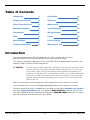
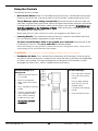
Unit Information. Enter the Model Number, Serial
Number, and the Date of Manufacture from the label
on your unit. This information is required for part or
warranty issues.
Model:
Serial:
Date of Manufacture:

HDS-18EA Alignment Lift 3 P/N 5900970 — Rev. C2 — March 2020
Table of Contents
Introduction 3 Installation 12
Shipping Information 4 Operation 61
Safety Considerations 4 Maintenance 65
Additional Products 5 Troubleshooting 67
Components 6 Wiring Diagram 68
FAQs 8 Labels 69
Specifications 9
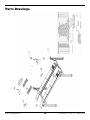
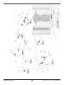
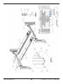
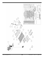
Parts Drawings 72
Installation Checklist 11 Maintenance Log 78
Introduction
This manual describes the HDS-18EA Alignment Lift, which is a heavy-duty, four-post
alignment/service Lift that can raise Vehicles up to 18,000 pounds (8,165 kg).
This manual is mandatory reading for all users of the HDS-18EA, including anyone who installs, uses,
maintains, repairs, or wants to know more about it.
⚠ DANGER Use care when installing, operating, maintaining, or repairing this equipment; failure
to do so could result in property damage, product damage, injury, or (in very rare
cases) death. Make sure only authorized personnel operate this equipment. All
repairs must be performed by an authorized technician. Do not make modifications
to the unit; this voids the warranty and increases the chances of injury or property
damage. Make sure to read and follow the instructions in this manual and on the
labels on the unit.
Keep this manual on or near the equipment so that anyone who uses or services it can read it.
If you are having issues, refer to the Troubleshooting section of this manual for assistance.
Technical support and service is available from your dealer, on the Web at bendpak.com/support,
by email at support@bendpak.com, or by phone at (800) 253-2363, extension 196. You may
also contact BendPak for parts replacement information at (800) 253-2363, extension 191; please
have the model and serial number of your unit available.

HDS-18EA Alignment Lift 4 P/N 5900970 — Rev. C2 — March 2020
Shipping Information
Your equipment was carefully checked before shipping. Nevertheless, you should thoroughly inspect
the shipment
before
you sign to acknowledge that you received it.
When you sign a bill of lading, it tells the carrier that the items on the invoice were received in good
condition.
To protect yourself, do not sign until
after
you have inspected the shipment.
If any of
the items listed on the bill of lading are missing or are damaged, do not accept the shipment until the
carrier makes a notation on the bill of lading that lists the missing and/or damaged goods.
If you discover missing or damaged goods
after
you receive the shipment and have signed the bill of
lading, notify the carrier at once and request the carrier to make an inspection. If the carrier will not
make an inspection, prepare a signed statement to the effect that you have notified the carrier (on a
specific date) and that the carrier has failed to comply with your request.
It is difficult to collect for loss or damage after you have given the carrier a signed bill of lading. If this
happens to you, file a claim with the carrier promptly. Support your claim with copies of the bill of
lading, freight bill, invoice, and photographs, if available.
Our willingness to assist in helping
you process your claim does not make us responsible for collection of claims or
replacement of lost or damaged materials.
Safety Considerations
Read this entire manual carefully before installing or using the product.
Do not
install or operate the product until you are familiar with all operating instructions and warnings. Do not
allow anyone else to operate it until they are familiar with all operating instructions and warnings. Keep
this manual on or near the product for future reference.
Read and follow the warnings and instructions on the labels on the product. Contact BendPak at
(800) 253-2363 or support@bendpak.com if you need replacement labels or a replacement
manual.
Safety Information
The following safety information applies to the HDS-18EA:
• The product is an alignment/service Lift. Use it only for its intended purposes. Visit the
Bendpak website for additional information about all of our Lifts.
• The product may only be operated by authorized, trained persons. Keep all untrained personnel
away from the product.
• When the Lift is in use, keep all body parts well away from it.
• Do not make any modifications to the Lift; this voids the warranty and increases the chances of
injury or property damage.
• Make sure all operators read and understand this Installation and Operation Manual. Keep the
manual near the Lift at all times.
• Make a visual inspection of the Lift
before
using it. Check for damaged, worn, or missing parts.
Do not use the product if you find any of these issues. Instead, take it out of service, then contact
an authorized repair facility, your dealer, or BendPak at (800) 253-2363 or
support@bendpak.com.
• BendPak recommends making a
thorough
inspection of the product at least once a year.
Replace any damaged or severely worn parts, decals, or warning labels.

HDS-18EA Alignment Lift 5 P/N 5900970 — Rev. C2 — March 2020
Symbols
Following are the symbols used in this manual:
⚠ DANGER Calls attention to an immediate hazard that will result in death or severe injury.
⚠ WARNING Calls attention to a hazard or unsafe practice that could result in death or severe
personal injury.
⚠ CAUTION Calls attention to a hazard or unsafe practice that could result in minor personal
injury, product damage, or property damage.
NOTICE Calls attention to a situation that, if not avoided, could result in product or property
damage.
Tip Calls attention to information that can help you use your product better.
Liability Information
BendPak Inc. assumes no liability for damages resulting from:
• Use of the equipment for purposes other than those described in this manual.
• Modifications to the equipment without prior, written permission from BendPak.
• Injury or death caused by modifying, disabling, overriding, or removing safety features.
• Damage to the equipment from external influences.
• Incorrect operation of the equipment.
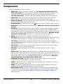
Additional Products
There are additional products you can use with your Lift:
• Aligner. An Aligner is a hardware/software product that lets you perform wheel alignments. If you
already have an Alignment Lift, like the HDS-18EA, simply purchase the Aligner and you can start
performing wheel alignments.
Refer to the Aligner page on the BendPak website for more information.
• Rolling Bridge Jack. A Rolling Bridge Jack raises the wheels of a Vehicle off the Runways of a
Lift, like an HDS-18EA, making it much easier to perform service such as brake jobs and
suspension work while the Vehicle is still on the Lift.
You can raise two wheels off the Runways if you have one Rolling Bridge Jack. It takes two Rolling
Bridge Jacks to raise all four wheels off the Runways.
Refer to the Rolling Bridge Jack page on the BendPak website for more information.
• WSA-100 Air/Electric Workstation. The Air/Electric Workstation adds air and electric
capabilities to your Lift. It includes four electrical outlets and specialized air service outlets, among
other features. Refer to the WSA-100 Air/Electric Workstation page on the BendPak
website for more information.
Note that SKU 5210436 is optimized for the HDS-18EA Alignment Lift.

HDS-18EA Alignment Lift 6 P/N 5900970 — Rev. C2 — March 2020
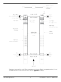
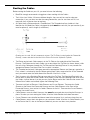
Components
The main components of your Lift include:
• Power Post. The Post that holds the Power Unit.
You must put the Power Post in the
Front left position
(refer to the drawing on the following page for orientation information). You
can tell the Power Post from the other Posts because it has two Mounting Brackets on it.
• The other three Posts. These Posts are interchangeable, although their Labels are different.
• Power Unit. An electric/hydraulic unit that connects to an electric power source and then
provides Hydraulic Fluid to the Hydraulic Cylinder that raises and lowers the Runways.
• Powerside Runway. The Runway on the same side as the Power Post. The Powerside Runway
has the Hydraulic Cylinder and the Cables under it.
• Offside Runway. The other Runway. It does
not
have an Hydraulic Cylinder or Cables under it.
• Utility Rails. Hold the optional Rolling Bridge Jacks.
Utility Rails must go on the inside of
the Lift.
• Crosstubes. One at the Front of the Lift, one at the Rear. The Crosstubes are hollow; the Cables
that raise and lower the Runways are routed through the Crosstubes. The Crosstubes are not
interchangeable: the Front Crosstube has a small opening (called a ‘Window’) that faces the inside,
the Rear Crosstube has a larger Window that also faces the inside of the Lift.
Windows open to
the inside of the Lift only
. Cables go into the Crosstubes through the Windows.
• Ramps. One for each Runway. Use them to drive onto and off of the Runways.
• Tire Stops. Located at the Front of the Lift, Tire Stops prevent the Vehicle’s front tires from going
any further forward. Additionally, we strongly recommend chocking the Vehicle’s rear tires.
• Turn Plates. Movable plates that go near the Front of each Runway; required for alignments.
You must orient both Runways so that their Turn Plates are at the Front of the Lift, whether you are
doing alignments or not.
• Filler Plates. Two per Runway, they sit on either side of the Turn Plate. Gives you the ability to
align Vehicles with a wide variety of wheel sizes.
• Slip Plate. A large movable plate on both Runways towards the Rear of the Lift; used for
alignments.
• Safety Locks. Once engaged, they hold the Runways in position, even if the power goes out or
there is a leak in the Hydraulic Hoses. Your Lift has 13 Safety Locks, spaced every four inches (100
mm). This lets you lock the Lift at just the right height for what you want to do. The Lift also has a
backup Slack Safety system; refer to About Safety Locks for more information.
Only leave
your Lift fully lowered or engaged on a Safety Lock.
• Pushbutton Air Valve. Holds the pushbutton that moves the Safety Locks away from the
Ladder so that they do not engage as you lower the Runways.
• Ladder. A piece of steel that is installed at the back of each Post. Each Ladder has 13 holes in it,
which are part of the Safety Lock system.
• Aligner. An optional, separate product that lets you perform Vehicle alignments. Refer to the
aligner page on the BendPak website for more information.
• Rolling Bridge Jacks. An optional, separate product that raises wheels of the Vehicle on the
Lift off the Runway, making it easier to perform brake jobs and suspension work while the Vehicle
is still on the Lift. Refer to the Rolling Bridge Jack page on the BendPak website for
more information.

HDS-18EA Alignment Lift 7 P/N 5900970 — Rev. C2 — March 2020
Drawing not necessarily to scale. Some components not shown. Aligner is a separate product; it is not
included with the Lift. The Front of the Lift is the end
opposite
the Ramps.

HDS-18EA Alignment Lift 8 P/N 5900970 — Rev. C2 — March 2020
Frequently Asked Questions
Question: What kinds of Vehicles can I put on my Lift?
Answer: Cars, trucks, SUVs; anything that fits on the Runways, up to 18,000 lbs (8,165 kg).
Q: What is an ‘alignment’ Lift?
A: A Lift with special components that allow it to be used to perform automotive alignments. The
HDS-18EA is an Alignment Lift. An alignment is an adjusting of the angles of a Vehicle’s wheels to
the manufacturer’s specifications, which generally reduces tire wear and makes the Vehicle drive
without pulling to one side. The HDS-18EA can also be used as a Service Lift or a Parking Lift. A
Service Lift gives access to the underside of a Vehicle for maintenance tasks. A Parking Lift lets
you park one Vehicle on the Runways and a second Vehicle under the Runways.
Q: How long does it take to raise or lower the Runways?
A: About 75 seconds.
Q: Does the Lift have to be anchored in place?
A: If you are using it as an Alignment Lift, then yes, you must anchor it. If not, then it is up to you. A
four-post Lift is pretty stable, but for safety reasons we recommend anchoring it.
Q: How high does the ceiling have to be?
A: It depends on the height of the Vehicles you are putting on the Runways and how high you raise
the Runways. If you are going to put a tall Vehicle on the Runways and raise it all the way up, you
should measure, in advance, to make sure there is enough room.
Q: Does it matter if I drive my Vehicles in front first or back them in?
A: We recommend driving your Vehicle in front first, because that makes it easier to center the
Vehicle’s wheels on the Runways. Nevertheless, you are not required to drive them in front first.
Whichever way you drive the Vehicle in, remember to put the wheels at the Front of the Lift up
against the Tire Stops and chock the wheels at the Rear.
Q: Will the Cables really hold my Vehicles?
A: Yes. Your Lift has .63 inch (16 mm) thick, aircraft-quality Cables (technically wire rope) that runs
through oversized sheaves, reducing friction on them and extending their life with minimal
maintenance.
Q: How long can I leave a Vehicle on a raised Runway?
A: As long as you want. Once the Lift is engaged on its Safety Locks, gravity holds it in position, so a
loss of power does not make it come down; it is going to stay where you left it. You should always
leave your Lift either fully lowered or engaged on its Safety Locks.
Q: Can I install my Lift outside?
A: Your Lift is approved for indoor installation and use only.
Outdoor installation is prohibited
.
Q: How many Safety Lock positions does my Lift have?
A: 13, spaced every 4 inches / 100 mm.

HDS-18EA Alignment Lift 9 P/N 5900970 — Rev. C2 — March 2020
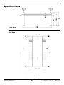
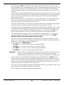
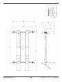
Specifications
Side View
Top View

HDS-18EA Alignment Lift 10 P/N 5900970 — Rev. C2 — March 2020
Model
HDS-18EA
Lifting capacity 18,000 lbs / 8,165 kg
Maximum capacity of front axle
9,000 lbs / 4,082 kg
Maximum capacity of rear axle
9,000 lbs / 4,082 kg
a Total width
153.5" / 3,899 mm
b Outside Posts length
257"/ 6,528 mm
c Total length (includes ramps)
309.25" / 7,856 mm
d Post height
91.25" / 2,318 mm
e Runway thickness
9.5" / 240 mm
f Maximum rise (height under Runways)
60" / 1,526 mm
g Maximum lifting height
69.5" / 1,766 mm
h Distance between Posts
133.5" / 3,391 mm
i Runway width
22" / 559 mm
j Width between Runways,
1
min.
38.5" / 980 mm
j Width between Runways,
1
max.
56" / 1,427 mm
k Runway length
263" / 22 feet / 6,680 mm
l Min 4-wheel alignment
2
83" / 2,108 mm
m Max 4-wheel alignment
2
138" / 3,505 mm
n Max 2-wheel alignment
2
211" / 5,359 mm
Min. wheelbase @ rated capacity
3
185" / 4,699 mm
Min. wheelbase @ 75 capacity
3
160" / 4,064 mm
Min. wheelbase @ 50 capacity
3
135" / 3,429 mm
Min. wheelbase @ 25 capacity
3
110" / 2,794 mm
Locking positions 13, spaced every 4" / 100 mm
Lifting time ~75 seconds
Motor
4
220 VAC, 60 Hz, 1 Ph
1
May be limited if you are using Rolling Bridge Jacks.
2
Can vary depending on wheel size.
3
The Lift supports less weight than its rated capacity when the Vehicle’s wheelbase is shorter; this is
because the wheels of such a Vehicle are closer to the middle of the Runways, where there is less
strength. For example, the maximum weight allowed on the Lift for a Vehicle with a wheelbase of
135" is 50 percent of the Lift’s rated capacity (9,000 lbs when the rated capacity is 18,000 lbs).
4
Special voltages available on request.
Specifications subject to change without notice.

HDS-18EA Alignment Lift 11 P/N 5900970 — Rev. C2 — March 2020
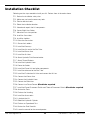
Installation Checklist
Following are the steps needed to install your Lift. Perform them in the order shown.
☐ 1. Review the installation safety rules.
☐ 2. Make sure you have the necessary tools.
☐ 3. Plan for electrical work.
☐ 4. Select the installation location.
☐ 5. Unload and unpack the Lift components.
☐ 6. Create Chalk Line Guides.
☐ 7. Move the Posts into position.
☐ 8. Install the Crosstubes.
☐ 9. Install the Ladders.
☐ 10. Raise the Crosstubes.
☐ 11. Secure the Ladders.
☐ 12. Install the Runways.
☐ 13. Install the first end of the Flex Tube.
☐ 14. Install the Return Line.
☐ 15. Install the Air Lines.
☐ 16. About Hydraulic Fluid Contamination.
☐ 17. About Thread Sealants.
☐ 18. Install the Hydraulic Hose.
☐ 19. Route the Cables.
☐ 20. Install the Power Unit and other components.
☐ 21. Install the other end of the Flex Tube.
☐ 22. Install the Pushbutton Air Valve and connect the Air Line.
☐ 23. Connect the Return Line.
☐ 24. Connect the Hydraulic Hose.
☐ 25. Contact the Electrician.
☐ 26. Connect to a Power Source (
Electrician required
).
☐ 27. Install the Power Disconnect Switch and Thermal Disconnect Switch (
Electrician required
).
☐ 28. Anchor the Posts.
☐ 29. Perform final Leveling.
☐ 30. Install the Accessories.
☐ 31. Lubricate the Lift.
☐ 32. Bleed the Hydraulic Cylinder.
☐ 33. Perform an Operational Test.
☐ 34. Review the Final Checklist.
☐ 35. Leave the manual for the owner/operator.

HDS-18EA Alignment Lift 12 P/N 5900970 — Rev. C2 — March 2020
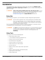
Installation
The installation process takes multiple steps. Perform them in the order listed.
Read the entire
Installation section before beginning the install
; this gives you a better understanding of the
process as a whole.
⚠ WARNING
Only use the factory-supplied parts that came with your Lift
. If you use
parts from a different source, you void your warranty and compromise the safety of
everyone who installs or uses the Lift. If you are missing parts, visit
bendpak.com/support or call (800) 253-2363, extension 191.
Being Safe
While installing this equipment, your safety depends on proper training and thoughtful operation.
⚠ WARNING Do not install this equipment unless you have automotive Lift installation training.
Always use proper lifting tools, such as a Forklift or Shop Crane, to move heavy
components. Do not install this equipment without reading and understanding this
manual and the safety labels on the unit.
Only fully trained personnel should be involved in installing this equipment. Pay attention at all times.
Use appropriate tools and lifting equipment. Stay clear of moving parts.
⚠ WARNING You
must
wear OSHA-approved (publication 3151) personal protective equipment
at all times when installing, using, maintaining, or repairing the Lift: leather gloves,
steel-toed boots, eye protection, back belts, and hearing protection are
mandatory
.
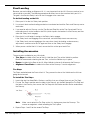
Using Tools
You may need some or all of the following tools:
• Rotary hammer drill (or similar)
• ¾ inch carbide bit (conforming to ANSI B212.15)
• Hammer, crow bar, and two sawhorses
• Four-foot level and 12-foot ladder
• Open-end wrench set, SAE and metric
• Socket and ratchet set, SAE and metric
• Hex key wrench set
• Medium crescent wrench, torque wrench, pipe wrench
• Chalk line
• Medium-sized flat screwdriver and needle-nose pliers
• Tape measure (25 feet or above)
• Forklift or Shop Crane

HDS-18EA Alignment Lift 13 P/N 5900970 — Rev. C2 — March 2020
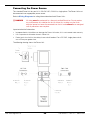
Planning for Electrical Work
You will need to have a licensed, certified Electrician available at some point during the installation.
⚠ DANGER All wiring
must
be performed by a licensed, certified Electrician.
Notify your Electrician in advance so that they come prepared with an appropriate cable for connecting
to the power source, a plug for the Power Unit, a Power Disconnect Switch, and a Thermal Disconnect
Switch. Refer to Contacting the Electrician for more information.
Your Electrician will need to:
• Connect an electric power source to the Power Unit. A 220 VAC power source is
required. Your Electrician will need to put an appropriate plug on the wiring on the Power Unit and
provide a power cable from the power source to the Power Unit.
• Install a Power Disconnect Switch. Ensures you can quickly and completely interrupt
electrical power to the Lift in the event of an electrical circuit fault, emergency situation, or when
equipment is undergoing service or maintenance. Put it within sight and reach of the Lift operator.
• Install a Thermal Disconnect Switch. Ensures the equipment shuts down in the event of an
overload or an overheated motor.
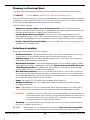
Selecting a Location
When selecting the location for your Lift, consider:
• Architectural plans. Consult the architectural plans for the desired installation location. Make
sure there are no issues between what you want to do and what the plans show.
• Available space. Make sure there is enough space for the Lift: front, back, sides, and above.
Refer to Specifications for measurements.
• Overhead obstructions. Check for overhead obstructions such as building supports, heaters,
electrical lines, low ceilings, hanging lights, and so on.
You do not want the Vehicles on the
Lift hitting obstructions
. As a general rule, the Lift location should have 80 inches of height
plus the height of the tallest Vehicle you plan on raising.
• Side and front clearances. You must leave room around the Lift. Leave at least five feet (60
inches) clear on each side, three feet (36 inches) clear on the Front of the Lift (you will need more
for the alignment equipment if you have an Aligner), and no obstructions at all at the Rear of the Lift
(so you can safely drive Vehicles onto the Runways).
• Power. You need a 220 VAC power source available for the Power Unit.
• Outdoor installations. Your Lift is approved for indoor installation and use only. Outdoor
installation is prohibited.
• Floor. Only install the Lift on a flat, concrete floor; do not install on asphalt or any other surface.
The surface must be level; do not install if the surface has more than three degrees of slope.
⚠ WARNING Installing your Lift on a surface with more than three degrees of slope could lead to
injury or even death. Only install the Lift on a level floor (defined as no more than 3/8
of an inch difference over the installation area). If your floor is not level, consider
making the floor level or using a different location.
• Shimming. If your concrete floor is not completely level, you can use Shims under the bases of
the Posts, as needed, to level the Lift.
NOTICE Because your Lift is an Alignment Lift, you want to
make it as level as possible
.
You can level your Lift in two ways: first, by shimming the Posts and second by

HDS-18EA Alignment Lift 14 P/N 5900970 — Rev. C2 — March 2020
adjusting the Nuts at the top of the Ladder. Both methods are covered in the
installation instructions, shimming near the beginning of the install, adjusting towards
the end.
To estimate your Shim requirements, use a transit level and targets to check for flatness. Use the
provided Shims as necessary.
NOTICE Do not shim a Post more than half an inch using the provided Shims and Anchor Bolts.
A maximum shim of 2 inches is possible by ordering optional Shim Plates. Contact
BendPak at (800) 253-2363, extension 191 to order. Please have the model and
serial number of your Lift available.
• Concrete specifications. Do not install the Lift on cracked or defective concrete. Make sure
the concrete is at least 4.25 inches thick, 3,000 PSI, and cured for a minimum of 28 days.
⚠ CAUTION BendPak Lifts are supplied with installation instructions and concrete anchors that
meet the criteria set by the American National Standard “Automotive Lifts – Safety
Requirements for Construction, Testing, and Validation”, ANSI/ALI ALCTV. You are
responsible for any special regional structural and/or seismic anchoring
requirements specified by any other agencies and/or codes such as the Uniform
Building Code (UBC) and/or International Building Code (IBC).
Be sure to check your floor for the possibility of it being a
post-tension slab
. In this case, you
must contact the building architect before drilling. Using ground penetrating radar may help you
find the tensioned steel.
⚠ WARNING Cutting through a tensioned cable can result in injury or death. Do not drill into a
post-tension slab unless the building architect confirms you are not going to hit
tensioned steel or you have located it using ground penetrating radar.
If colored
sheath comes up during drilling, stop drilling immediately
.
Unloading and Unpacking
Try to have the components of the Lift unloaded near the installation location.
Once the components are unloaded, they are your responsibility to move around. As the Lift includes a
number of heavy pieces, the closer you unload them to the installation location, the better off you are.
⚠ CAUTION Some Lift components are very heavy; if handled incorrectly, they can damage
materials like tile, sandstone, and brick. Try to handle the Lift components just
twice: once when delivered and once when moved into position. You must have a
Forklift or Shop Crane to move them into position. Use care when moving them.
⚠ WARNING The Posts and Runways are delivered with stabilizing structures on each end. Be
very careful when removing these stabilizing structures; the Posts and Runways
can shift or even fall. If they fall on a person, they can cause serious injury.

HDS-18EA Alignment Lift 15 P/N 5900970 — Rev. C2 — March 2020
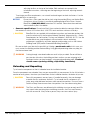
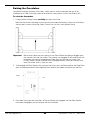
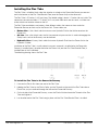
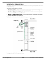
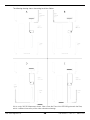
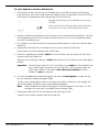
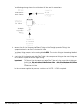
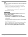
Creating Chalk Line Guides
Use Chalk Line Guides to ensure that your Posts get installed correctly.
Create the Chalk Line Guides so that the outside edges of all four Post bases fit into the corners
created by the Chalk Line Guides.
Refer to Specifications to determine the Total Width and Outside Posts Length values for
your Lift.
Note: Do
not
use the Total Length value; this includes the Ramps, which are not taken into
consideration for creating Chalk Line Guides.
Drawing not necessarily to scale. Some components not shown.

HDS-18EA Alignment Lift 16 P/N 5900970 — Rev. C2 — March 2020
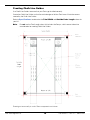
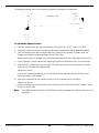
To create Chalk Line Guides:
1. Create the Front Chalk Line where you want the Front of the Lift.
Make the Front Chalk Line longer than the Total Width setting for your Lift model.
Tip If you are going to be using the Lift to do alignments, remember to leave room at the
Front of the Lift for the alignment equipment.
2. Create the Powerside and Offside Chalk Lines at 90° angles to the Front Chalk Line and parallel to
each other. Make the Powerside and Offside Chalk Lines longer than the Outside Posts Length
setting for your Lift model.
The Powerside and Offside Chalk Lines must be parallel to each other.
Measure to verify that this is true.
3. Create the Rear Chalk Line parallel to the Front Chalk Line. Make the Rear Chalk Line longer than
the Total Width setting for your Lift model.
The Front and Rear Chalk Lines must also be parallel to each other.
Measure to verify that this is true.
4. Before moving the Posts into position, measure
diagonally
to make sure the two diagonal
measurements are the same. This ensures your layout is correct.
Do not forget to check the diagonals.
5. When you move the Posts into position, put the outside edges of the bases inside the corners
created by the Chalk Line Guides.
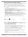
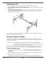
Moving the Posts into Position
Use a Forklift or Shop Crane to move the Posts. You need to have at least two people work together
to stand up the Posts.
⚠ DANGER The Posts are very heavy and awkward; be very careful when handling them.
If
they fall on a person, they will cause injury
.
To move the Posts into position:
1. Using a Forklift or Shop Crane, move the four Posts, one at a time, to the inside corners of the
Chalk Line Guides.
Important: Position the Power Post at its
required
location. The other three Posts can go at any
of the remaining Post locations. They are identical, but for the Labels on them.
2. Stand up each Post. Have at least two people work together to stand up a Post.
⚠ CAUTION Use caution when walking around the Posts; they are not anchored down at this
point, so it is possible to knock them over, which could cause injury.
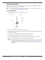
3. Use a Transit Level to estimate the Shim requirements: use a target to find the difference in height
between the Posts. The difference is the estimated amount of Shim thickness you will need.
Do not use Shims and/or Anchor Bolts to Shim more than half an inch per Post. You can order
2 inch
Shim plates
for extreme cases.
4.
Do not anchor the Posts at this point.

HDS-18EA Alignment Lift 17 P/N 5900970 — Rev. C2 — March 2020
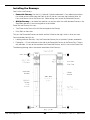
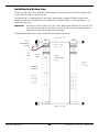
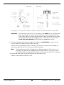
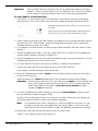
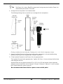
Installing the Crosstubes
Your Lift has two Crosstubes:
• Front Crosstube: Has the Small Window, where two Cable Sheaves go. Located at the Front of
the Lift, with the Window facing the inside.
• Rear Crosstube: Has the Large Window, where four Cable Sheaves go. Located at the Rear of
the Lift, with the Window facing the inside.
Both Crosstubes are hollow, which allows the Cables to be run through them to the Posts.
The following drawing shows both Crosstubes and additional components.
Drawing not necessarily to scale. Some components not shown.
Crosstubes have a Crosstube Gusset on both ends, for a total of four Crosstube Gussets per Lift.

HDS-18EA Alignment Lift 18 P/N 5900970 — Rev. C2 — March 2020
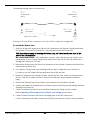
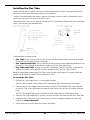
To install the Crosstubes:
1. Orient the Crosstubes in their required locations:
• Front Crosstube: must be at the Front of the Lift with the Small Window facing the inside.
• Rear Crosstube: must be at the Rear of the Lift with the Large Window facing the inside.
Both Windows must be on the Powerside.
The Crosstubes
must
be installed in these orientations.
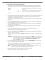
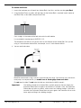
2. Put the Slide Blocks into place on the outside ends of each Gusset (
4 Slide Blocks per
Gusset
, 16 total for the Lift).
Align the holes in the Slide Blocks with the rods on the sides of the Gusset, then press the Slide
Blocks in. Make sure the Slide Blocks are oriented so that they create a Slot when pushed in.
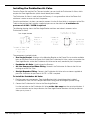
The following drawing shows how to correctly install two Slide Blocks onto a Gusset.
The four Slide Blocks on a Gusset, when put into place, create two Slots. There is one Slot at the
top of the Gusset and a second Slot at the bottom; the Ladders, when you install them,
must
go
through
both
Slots on the Gusset.
⚠ WARNING If the Slide Blocks are not correctly installed, then the Slots for the Ladder are not
created. In such a case, the Safety Locks will not work correctly, which endangers
everyone who uses the Lift. Make sure to correctly install the Slide Blocks.
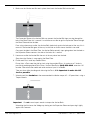
The following drawing shows the Slot created by two Slide Blocks.
3. Using a Forklift or Shop Crane, raise the Crosstube with the Slide Blocks installed above the top of
the two Posts that it goes between, lower it to just over the top of the Post, orient the Slide Blocks
over the openings in the Posts, then slide the Crosstube down.
4. Perform Steps 2 and 3 for the second Crosstube.

HDS-18EA Alignment Lift 19 P/N 5900970 — Rev. C2 — March 2020
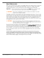
About Safety Locks
Safety Locks hold the Runways in place. Once engaged, Safety Locks hold the Runways in place even
if the power goes out or the Hydraulic Hoses break or leak. Your Lift has 13 Safety Lock positions,
spaced every four inches / 100 mm. Each Post has its own Ladder and set of Safety Locks.
Important: Simply raising the Runways does not necessarily
engage
them on the Safety Locks.
You must back the Runways down onto the Safety Locks to engage them.
⚠ WARNING Safety Locks are dependent on correct installation of the Ladders. Pay careful
attention when installing the Ladders.
The Ladders, one per Post, are steel pieces with 13 holes spaced every four inches / 100 mm. As you
raise the Runways, the Safety Locks move into the holes in the Ladder; these are the sounds you hear
when the Runways are moving. When you move the Runways back down a little after passing a Safety
Lock, the Safety Locks engage. Once they are engaged, Safety Locks stay engaged until you are
ready to lower the Runways. Even if the power goes out or one of the Hydraulic Hoses breaks or leaks,
the engaged Safety Locks hold the Runways in place.
⚠ WARNING Always leave the Runways either fully lowered or engaged on their Safety Locks.
When you engage the Safety Locks at a desired height, check to make sure that all
four Safety Locks (one per Post) are engaged.
How do the Runways come down if you have engaged the Safety Locks? To lower the Runways, you
raise them a few inches (to get them off the Safety Locks), then
press and hold down
the pushbutton
on the Pushbutton Air Valve. While you hold down the pushbutton, the Safety Locks are moved away
from the Ladders; in this position, they cannot engage, which allows the Runways to be lowered.
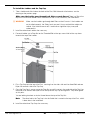
Out of an abundance of caution, your Lift has a second, independent Safety Lock system called the
Slack Safeties.
The Slack Safeties are physically located next to the Safety Locks on the ends of the Crosstube
Gussets. They are different from the Safety Locks in that when the Cables are taut (which they are
during normal operation), they hold the Slack Safeties away from the Ladder so that the Slack Safeties
cannot engage. However, if a Cable were to break (which very rarely happens), the Slack Safety for the
broken Cable immediately engages, preventing the Runways from falling.

HDS-18EA Alignment Lift 20 P/N 5900970 — Rev. C2 — March 2020
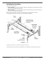
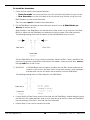
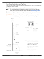
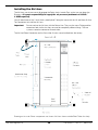
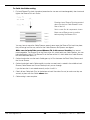
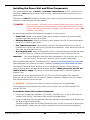
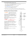
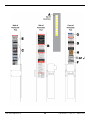
Installing the Ladders and Top Cap
Your Lift has four Ladders (one per Post); each gets installed on the inside back of a Post. Ladders are
secured at the top and the bottom.
The Top Caps secure the Ladder at the top of each Post and hold the ends of the Cables.
Note: It is much easier to secure the bottom of the Ladders once the Crosstubes have been
raised, so that portion of installing the Ladders is described in Securing the Ladders.
Each Ladder has 13 holes in it, spaced four inches / 100 mm apart; these holes are the Safety Locks.
Each Ladder has a Bolt Hole at the bottom and a Threaded Bolt at the top.
⚠ WARNING Make sure to install the Ladders correctly. If they are not installed correctly, the
Safety Locks on your Lift may not hold the weight of a Vehicle, putting anyone
under the Lift in danger.
Page is loading ...
Page is loading ...
Page is loading ...
Page is loading ...
Page is loading ...
Page is loading ...
Page is loading ...
Page is loading ...
Page is loading ...
Page is loading ...
Page is loading ...
Page is loading ...
Page is loading ...
Page is loading ...
Page is loading ...
Page is loading ...
Page is loading ...
Page is loading ...
Page is loading ...
Page is loading ...
Page is loading ...
Page is loading ...
Page is loading ...
Page is loading ...
Page is loading ...
Page is loading ...
Page is loading ...
Page is loading ...
Page is loading ...
Page is loading ...
Page is loading ...
Page is loading ...
Page is loading ...
Page is loading ...
Page is loading ...
Page is loading ...
Page is loading ...
Page is loading ...
Page is loading ...
Page is loading ...
Page is loading ...
Page is loading ...
Page is loading ...
Page is loading ...
Page is loading ...
Page is loading ...
Page is loading ...
Page is loading ...
Page is loading ...
Page is loading ...
Page is loading ...
Page is loading ...
Page is loading ...
Page is loading ...
Page is loading ...
Page is loading ...
Page is loading ...
Page is loading ...
Page is loading ...
Page is loading ...
-
 1
1
-
 2
2
-
 3
3
-
 4
4
-
 5
5
-
 6
6
-
 7
7
-
 8
8
-
 9
9
-
 10
10
-
 11
11
-
 12
12
-
 13
13
-
 14
14
-
 15
15
-
 16
16
-
 17
17
-
 18
18
-
 19
19
-
 20
20
-
 21
21
-
 22
22
-
 23
23
-
 24
24
-
 25
25
-
 26
26
-
 27
27
-
 28
28
-
 29
29
-
 30
30
-
 31
31
-
 32
32
-
 33
33
-
 34
34
-
 35
35
-
 36
36
-
 37
37
-
 38
38
-
 39
39
-
 40
40
-
 41
41
-
 42
42
-
 43
43
-
 44
44
-
 45
45
-
 46
46
-
 47
47
-
 48
48
-
 49
49
-
 50
50
-
 51
51
-
 52
52
-
 53
53
-
 54
54
-
 55
55
-
 56
56
-
 57
57
-
 58
58
-
 59
59
-
 60
60
-
 61
61
-
 62
62
-
 63
63
-
 64
64
-
 65
65
-
 66
66
-
 67
67
-
 68
68
-
 69
69
-
 70
70
-
 71
71
-
 72
72
-
 73
73
-
 74
74
-
 75
75
-
 76
76
-
 77
77
-
 78
78
-
 79
79
-
 80
80


BendPak HDS-18E-18EA Owner's manual
- Type
- Owner's manual
- This manual is also suitable for
Ask a question and I''ll find the answer in the document
Finding information in a document is now easier with AI
Related papers
-
BendPak LR-5T Owner's manual
-
-
-
-
-
-
-
-
-
Other documents
-
Panasonic DS-52 Installation guide
-
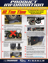 TradeQuip BTR20TP Truck Ramp User manual
-
 TCE T11000-2OH-33 Operating instructions
-
 Stonegate Decorative Wood Bridge Owner's manual
-
Toro Gusset Kit, Z593 Series Z Master Mowers Installation guide
-
Red Head 07501 Operating instructions
-
-
-
Ranger RFJ-2TX Owner's manual
-
Arrow AK600 Installation guide


