Page is loading ...

, I
i
I I
r·
\
INSTRUCTION MANUAL
For
CIRCUIT BREAKER
TEST
SETS
MODEL DDA-3000/6000
It is essential
that
this
instruction
book
be read
thoroughly
by
the operator
or
the
test
equipment
before putting
the
equipment
in
service.
PartNo._17177
Rev. 4, 7/3/02

Revision History
Revision
ECN#
Date
1 27168
11/11/96
2 27356
11/14/97
3 27999
3/12198
4
29358
7/3/02
IMPORTANT
The
information and data contained within this instruction manual are proprietary
property
of
A
VO
International.
The
equipment described herein may be protected
by
one
or
more
U.
S.
patents. A
VO
International specifically reserves to itself all rights
to
such proprietary information as well as all rights under any such patent, none
of
which
is waived
by
the submission
of
this instruction manual.
The
recipient,
if
a Government agency, acknowledges that this instruction book and the
equipment described were procured with "Limited Rights" to technical data as described
in
ASPR 9-203
(b).
Copyright
AVO
International
Inc.
1995, 1996, 1997

TABLE OF CONTENTS
SECTION I ................................................................................................................................................................. 1
1.
INTRODUCTION .......................................................................................................................................... 1
A.
GENERAL DESCRIPTION & SPEFICATION BULLETIN ................................................................... 1
1.
DESCRIPTION
of
CONTROLS
and
INSTRUMENTATION ................................................................... 4
A.
GENERAL DESCRiPTION ...................................................................................................................... 4
B.
CONTROLS AND INSTRUMENTATION .............................................................................................. 4
SECTION III ............................................................................................................................................................... 9
1.
FRONT PANEL DISPLAY AND PROGRAMMING MENUS ................................................................... 9
2.
Flow Diagram
of
Display Menus ...............................................................................................................
10
A.
METERING DISPLAY ............................................................................................................................
10
B.
MAIN MENU ............................................................................................................................................
10
, i
C.
LCD CONTRAST MENU ...................................................................................................................
11
I
I .
i
I
~
,
D.
SCR CONTROL MENU .....................................................................................................................
11
E.
PULSE DURATION AND FIRING ANGLE MENUS ..........................................................................
11
F.
ACQUISITION CONTROL
MENU
........................................................................................................
12
SECTION IV INPUT AND OUTPUT CIRCUITS ................................................................................................
14
1.
INPUT: ..........................................................................................................................................................
14
A.
INPUT VOLTAGE ...................................................................................................................................
14
B.
INPUT LEADS .........................................................................................................................................
14
C.
GROUNDING ......................................................................................................................................
14
D.
SAFETY PRECAUTIONS ..................................................................................................................
14
2.
OUTPUT ......................................................................................................................................................
14
A.
SELECTION OF OUTPUT CONNECTIONS ......................................................................................
14
.B.
OUTPUT CONNECTIONS ....................................................................................................................
15
C.
DUTY RATINGS AND OVERLOAD CAPACITIES ........................................................................
16
SECTION V .............................................................................................................................................................
19
1.
TEST PROCEDURES FOR TESTING
OF
MOTOR OVERLOAD RELAYS ......................................
19
2.
TEST PROCEDURE FOR TESTING
OF
MOLDED CASE AND LOW VOLTAGE POWER CIRCUIT
BREAKERS .........................................................................................................................................................
22
3.
MAINTENANCE OF PROTECTIVE APPARATUS MAINTENANCE OF MOTOR OVERLOAD
RELAYS
...............................................................................................................................................................
26
4.
MAINTENANCE OF MOLDED CASE CIRCUIT BREAKERS ..............................................................
29
5.
MAINTENANCE OF LOW VOLTAGE POWER CIRCUIT BREAKERS .............................................
31
6.
SUGGESTED RECORD FORMS - INSPECTION AND TEST RESUL TS .........................................
33
SECTION
VI
............................................................................................................................................................
34
2.
SERVICE DATA ..........................................................................................................................................
34
SECTION VII ...........................................................................................................................................................
37
1.
SCHEMATIC DRAWiNG ...........................................................................................................................
37

I I
1-'
i
..
[
I'
I
Megger
..
DDA-3000
and
DDA-6000
Universal Circuit Breaker Test
Sets
DDA-3000
and
DDA-6000
Universal
Circuit
Breaker
Test Sets
DESCRIPTION
Incorporating
the
latest technological advancements,
Models
DDA-3000
and
DDA-6000 Series are designed
specifically
to
test low-voltage
power
and
molded-case
circuit breakers
equipped
with thermal, magnetic
or
solid-state trip devices.
The
units are fully compliant
with
NEMA
AB-4 test guidelines.
Tests are
performed
by
simulating
an
overload
or
fault
condition. Each test
set
is
an
integrated test system that
provides a variable, high-current output. The test sets
incorporate all control circuitry
and
instrumentation
necessary
to
test direct-acting circuit breakers accurately,
efficiently
and
safely.
The unique transformer
and
circuit design results in a very
high-capacity test set in a very compact size. Advanced
digital
control
and
instrumentation provides exact testing capacity.
APPLICATIONS
Universal
in
application,
the
test sets will test virtually
all low-voltage, molded-case
and
metal-clad, direct-acting
ac circuit breakers
produced
by
General Electric,
Westinghouse, Federal Pacific, Square D, Gould,
ABB,
ITE,
Siemens
and
other
manufacturers.
Model
DDA-3000 is rated for testing breakers
up
to
3000 amperes. Model DDA-6000
is
rated for testing
breakers
up
to 6000 amperes. Rugged
and
reliable,
Megger circuit
breaker
test sets will provide years
of
trouble-free operation.
The test sets also
may
be
used
for other high-current
applications,
such
as verifying
the
ratio
of
current
•
Model
DDA-1
Digital
Data
Acquisition
Instrumentation
and
Control
System
•
High-current
output:
60,000
A
for
Model
DDA-6000;
35,000
A
for
Model
DDA-3000
•
Digital
signal processing (DSP)
technology
•
Variable
pulse
time
and
firing
angle
output
current
control
•
Compliant
with
NEMA
AB-4
test
guidelines
transformers
and
performing
heat
runs
or
primary injection
testing
of
high-voltage breakers
and
their associated
protective relays.
All
Model DDA-3000
and
DDA-6000 test sets have identical
features, instrumentation
and
operational characteristics.
The
only changes
in
the specifications
among
the
units are
their size, weight
and
maximum output-current capacity.
FEATURES
AND
BENEFITS
III Initiating
control
circuit: Fully digital initiating control
circuit provides
both
pulsed
and
maintained control
modes
of
output
duration.
The
pulsed
mode
automatically pulses
the
output
to
any
programmed
pulse duration. This provides additional testing
capabilities for electromechanical
and
solid-state trip
devices. A short pulse duration also limits
the
preheating
of
the
breaker
under
test while setting
the
test current.
In
the
maintained mode,
the
output
remains energized
until manually
turned
off or, during timing test, until the
device
under
test operates,
which
both
stops
the
timer
and
de-energizes the output.
II
Zero
de
offset:
Use
of
digitally controlled
SCRs
instead
of
a contactor
to
initiate
the
output
of
the
test
set
eliminates closing-time error
and
thereby
ensures precise
initiation at
the
zero crossover
point
of
the
output
current waveform every time. Initiation at
the
zero
crossover
point
ensures symmetrical
output
current
by
eliminating
dc
offset in
the
current waveform. Therefore
accurate, repeatable test results
are
assured
even
with
currents
of
very short duration, as
when
conducting tests
of
instantaneous
or
short-time delay trip elements.

Meggerm
DDA-3000
and
DDA-6000
Universal Circuit Breaker Test
Sets
The
Model
DDA-1 control
panel
digitally
s.amples
the
output
current
and
mathematically
calculates
the
current supplied
to
the
breaker
under
test.
The digital control
of
the
SCRs
also allows the unit
to
initiate at
any
point
within 90 degrees
of
the zero
crossover
point
of
the
output-current waveform. This
will allow
the
intentional insertion
of
a dc offset into
the
waveform for a complete investigation
of
a breaker's
operation.
•
Compact
enclosure:
Improvements
in
transformer
and
circuit design have resulted in a very high-capacity test
set
in
a single, relatively small enclosure. For safety
and
mobility,
the
test
set
is
housed
in a single, rugged,
sheet
metal enclosure with a
low
center
of
gravity,
tow
ring,
lifting eyes
and
large, locking swivel casters with brakes.
To increase maneuverability, all four casters swivel;
however,
they
also
can
be
locked into a fixed pOSition
easily. The
compact
size
of
test sets permits easy
movement
through
narrow doors. Controls
and
instrumentation are positioned so that the operator
can
Simultaneously observe
the
circuit breaker
under
test.
•
Construction:
Built for years
of
trouble-free, reliable
operation,
the
test sets include rugged instrumentation
and controls designed to withstand
the
vibration
and
shock
of
frequent transportation. They
need
never
be
removed from
the
enclosure .
• Protection: Fuse, circuit breaker
and
overload
protective devices are incorporated. The output-initiating
SCRs
are forced-air cooled,
and
temperature sensors
provide protection from overheating. Emergency
stop
pushbutton is
provided
to de-energize all
input
power
to
the test set.
•
Ground
safety
interlock:
An
interlock circuit ensures
that
the
test
set
chassis
is
connected to system
ground
before
the
output
of
the
test
set
can
be
energized.
•
Accessory
outlet: A ground-fault-protected, 120 volt
outlet with a capacity
of
1.2
kVA
is
proVided for
convenient
connection
of
accessory equipment.
Other
voltages are available internally for customer-installed
outlets.
INSTRUMENTATION
AND
CONTROLS
Model
DDA-l:
The
Digital Data Acquisition
instrumentation
and
control system was deSigned
specifically
to
provide precise control
of
the
output
current
and
accurate metering
of
the
breaker
under
test.
Model DDA-1 uses the latest in digital signal processing
(DSP) technology. This technology provides complete
digital control
of
the
SCRs
and
digitally samples
the
output
current for high-accuracy measurements.
Digital
ammeter:
Model DDA-1 samples
the
output
current digitally
and
mathematically calculates
the
current
that is supplied to
the
breaker
under
test. This process
increases
the
accuracy
of
the
ammeter systems
and
provides extreme flexibility in
what
current value is
displayed. For example,
when
the
test
set
is
delivering a
continuous current, the digital
ammeter
is continuously
sampling
the
output
waveform
and
can
display a true rms
value
of
the
current.
For measuring short-duration currents, Model DDA-1 can
calculate
the
output
current in
the
following ways via
selection from the soft control buttons
on
the
panel:
1.
For any
output
current greater
than
half a cycle, Model
DDA-1
can
calculate the true rms value
of
the
output
current pulse. For any
output
less
than
half a cycle, a true
rms measurement
is
invalid.
2.
For
any
current pulse, Model DDA-1
can
measure
th~
peak
current
and
calculate
an
anticipated rms value
of
the
current from
the
peak
current.
This multiple-current calculation feature is also useful
when
testing different styles
of
solid-state trip devices. This
feature allows the test set to simulate a similar type
of
current calculation that is being
used
by
the
various solid-
state trip devices.
Digital
timer: Thanks to digital signal processing
technology, Model DDA-1's system
knows
exactly
when
current is
present
and
when
the
breaker
under
test opens.
This provides high-accuracy timing
even
when
testing the
instantaneous trip function
on
fast-acting breakers.
In
addition,
the
digital timer
can
display
the
breaker
trip time
in
cycles
or
seconds.
A completely digital, solid-state circuit starts
the
timer
automatically
when
the
output
current starts to flow
and
stops it
when
the
device
under
test operates. This circuit
will accommodate a variety
of
test conditions including:

I 1
I i
Megger"
The
DDA
Series
offers
high
capacity
in
a
single,
relatively
compad
enclosure
that
can
be
easily
maneuvered.
.1.
When
testing a circuit breaker
or
a device
which
has
no
auxiliary contact to monitor (e.g., a single-pole circuit
breaker),
the
timer starts
when
the
output
current starts
to
flow
and
stops
when
the
output
current is interrupted.
2.
When
testing a device
and
monitoring normally closed
contacts,
the
timer starts
when
the
output
current starts
to
flow
and
stops
when
the
contacts
open.
3.
When
testing a device
and
monitoring normally
open
contacts,
the
timer starts
when
the
output
current starts
to
flow
and
stops
when
the
contacts close.
Digital
voltmeter:
Model DDA-l
can
be
used
to
measure
the
input
voltage
to
the
test set
or
the
output
voltage from
the
test set.
It
also
can
be
used
as a diagnostic tool
to
evaluate contact condition
by
measuring the voltage
drop
across
breaker
contacts while subject
to
high current.
Panel indicators: Panel lamps incorporated for
operator
safety
and
convenience, indicate:
1.
Output
of
the
set ENERGIZED
2.
Thermal
WARNING
or
SHUIDOWN
3.
GROUND INTERLOCK
open
4.
OVER
RANGE
of
ammeter
External initiate circuit: Allows initiation
of
the test
set
from a
remote
location
when
desired.
SPECIFICATIONS
Input
Because Model DDA-3000/-6000 is
used
all over
the
world
to
test
low-voltage circuit breakers, there are a
number
of
test sets
designed
to
contend
with
the
many
different input voltages
and
frequencies.
When
ordering, select
the
test set which best suits
the
power
system available.
The
standard input
power
requirements for
the
DDA-3000
and
DDA-6000 series are as follows:
Output
Output
Circuit:
The
output
of
the
test set is easily adjustable from
zero
to
the
maximum
current available through
the
impedance
of
the
device
under
test.
Two
output
ranges are provided
to
accommodate
a variety
of
load
circuit impedances.
For
high
impedance
devices,
the
output
can
be
connected
in
DDA-3000
and
DDA-6000
Universal
Circuit
Breaker
Test
Sets
Output
Current
Maximum
Continuous
Current
Maximum
Current
Maximum Current
Through
a
Through
a
Short
Circuit
Breaker
Circuit
4500
A
35,000
A
60,000 A
4446
A
2S,OOOA
48,000
A
4446
A
2S,OOOA
48,000
A
DOA6000.
6250
A
60,000
A
100,000 A
6175 A
50,000
A
SO,OOOA
:ODA-.600:?
6175A
50,000
A
SO,OOOA
··;M~d~
..
~:2··I-W_E_IG,-H_T-+-
____
D_I_M_E_NTS_I_O_N_S
___
--I
'~'''
..•. ',.,
Ib
kg
H X W X D
(in.)
H X W X D
(em)
PR);;-'3QOOS¢t!¢S1000 454
46X46X28in.
117X117X71em
DDA~600(rs~i,~f
1200 545 46 X 55 X 28 in. 117 X 140 X
71
em
'.-
" .
,,~~
.
.'.
-;
.yo:.:.:':
,,:-,-,.
series (with the series
bar
provided)
to
double
the
output
voltage
at a
reduced
maximum current.
The maximum current available from
the
test
set
is determined
primarily
by
the impedance
of
the
load
circuit.
The duration
of
the available current is determined primarily
by
thermal conditions within
the
test set.
Output
Connections:
To provide
maximum
utilization
of
the
output
available from
the
test set,
each
set
is
equipped
with a
Megger stab
adapter
board
and
stab
sets Model
CBS-1
and
Model
CBS-2
for
use
with drawout style, metal-clad breakers. The stabs
eliminate the significant losses that
occur
if leads are
used
to
connect
the
breaker
under
test to
the
test set. Cables must
be
used
when
testing molded-case
breakers
or
other
devices which
will
not
connect directly
to
the
stabs.
Duty
Cycle:
The
test
set
will
supply
the
rated continuous current
indicated for 30 minutes, followed
by
30 minutes off.
Maximum
Output
Current:
Model DDA-3000/-6000 Series will
produce
the
following outputs
at
rated
input
voltage:
Instrumentation
Digital
Ammeter
Operating
Mode
Memory
Continuous
Digital
Display:
5-digit display
with
0.281 in.
C7
mm) numerals
Ranges:
200/2000/20,000/200,000 A
Overall
Ammeter
System
Accuracy
Continuous ±1%
of
reading
Peak Pulse
±2%
of
reading
RMS
Pulse ±1.5%
of
reading
Digital
Timer
Digital
Display:
5-digit display
with
0.281 in.
C7
mm) numerals
Ranges
0.0001
to
99999 seconds
0.0001
to
99999 cycles
Accuracy:
± 1 %
of
reading
Digital
Voltmeter
Operating
Mode
Input
voltage
Output voltage
External voltage
Digital
Display:
5-digit display
with
0.281 in. (7
mm)
numerals
Ranges:
0
to
600 V
Accuracy:
±
1%
of
reading

Megger"
OPTIONAL
ACCESSORIES
Protective
Cover
A
tough
cover
made
of
heavyweight, reinforced, vinyl-coated
nylon
is available for protecting the test
set
from oil,
dust
or
other
particulate matter during storage.
It conforms to
Mil-C-43006D
and
passes Mil-C-20696B test for
oil
and
hydrocarbon resistance.
It
will withstand continuous
exposure
to
temperatures ranging from -40
to
+ 180
0
F
(-40
to
+820
C),
and
the fire-retardant material is treated
with
fungal
and
ultraviolet ray inhibitors.
Input
Autotransformer
If
the
nominal input voltage for the test set is
not
available,
or
if
use
at
different locations requires the
use
of
a variety
of
input
voltages,
an
autotransformer may
be
used.
ORDERING
INFORMATION
Item
(Qty)
Cat.
No.
Model
DDA-3000 DDA-3000
Model
DDA-3001 DDA-3001
Model
DDA-3002 DDA-3002
Model
DDA-6000 DDA-6000
Model
DDA-6001 DDA-6001
Model
DDA-6002 DDA-6002
Included Accessories
Standard stab sets
CBS-1
and
CBS-2
Leads
Timer
leads, 12
ft
(3.7 m) [2] 2997
Input
leads,
15-ft
(4.5-m), 4/0 cable [2] 17163
Fuses
Fuse
500
V,
6 A [2]
9377
Fuse
250
V,
1.5 A [5]
950
Stab series
bar
[1]
5532
Instruction manual [1]
17176
Optional
Accessories
Input
autotransformer
AT-1,
AT-4
Leads included
with
input
autotransformer
Interconnect
leads,
10-ft
(3-m), 4/0 cable [2]
17164
Jumper
lead [1]
Protective cover
Model
CBS-3
stabs
UK
Archcliffe
Road,
Dover
CT17
9EN
England
T (0) 1
304
502101
F
(0)
1
304
207342
17527
PC-1
Contact Technical
Sales
UNITED
STATES
4271
Bronze
Way
Dallas,
TX
75237-1019
U5A
T 1
800
723
2861
T 1
214
333
3201
F 1
214
331
7399
DDA-3000
and
DDA-6000
Universal Circuit Breaker
Test
Sets
The multitapped autotransformer is
equipped
with a
power
on/off
switch, appropriate sockets, plugs, interconnect
and
tap selector
cables.
It
is
housed
in a rugged sheet-metal enclosure with casters
and
handles.
All
voltages are single-phase with a tolerance
of
±5%.
Input taps
of
240 volts
and
below
are
not
recommended
for obtaining
maximum output
of
the test set.
For
other
combinations
of
input
and
output voltages, contact Megger.
::.+'~fl;~.!.;'"
7.,EIG::
H X W X
:~:~NS~O:~
X D
(em)
PQ~~3,~9(t~~fjeS.1000
454
46
X
46
X
28
in.
117 X 117 X
71
em
D().I(6aOQS~ri~S
1200 545
46
X 55 X 28
in.
117 X 140 X
71
em
OTHER
TECHNICAL SALES OFFICES
Norristown
U5A,
Toronto
CANADA,
Mumbai
INDIA,
Paris
FRANCE,
Sydney
AUSTRALIA,
Madrid
5PAIN
and
The
Kingdom
of
BAHRAIN.
ISO STATEMENT
Registered
to
ISO
9001:1994 Reg no. Q 09250
Registered
to
ISO
14001
Reg
no.
EMS
61597
DDA3000_6000_DS_en_ V11
www.megger.com
Megger
is
a
registered
trademark

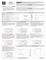
B.
SPECIFICATIONS
DDA-3000/3001/3002 and 6000/6001/6002 Specifications
Input
Input Input Input
Voltage
Frequency Current
(Single-
phase)
460V±5%
60 Hz
200A
380V±5%
50 Hz 200 A
415V±5%
50 Hz
200 A
460V±5%
60 Hz
350 A
380V±5%
50 Hz
350A
415V±5%
50
Hz
350 A
Output
Output Current
Maximum Maximum Current
Maximum Current
Continuous Through a
Through a
Short
Current
Circuit Breaker
Circuit
4500 A
35,000 A
60,000 A
4446 A
28,000 A
48,000 A
4446 A
28,000 A
48,000 A
6250 A 60,000 A
100,000 A
6175A
50,000 A
80,000 A
6175A
50,000 A
80,000 A
I'
f
\
~
!
I
I
2

Instrumentation
Digital
Ammeter
Operating Mode
Memory
Continuous
Digital Display
5 - digit display with 0.281
in
(7
mm) numerals
Ranges
200/2,000/20,000/200,000
A
Accuracy
Continuous - ± 1 %
of
Reading
Pulse (Peak) - ± 1.5%
of
Reading
Pulse (RMS) - ± 2%
of
Reading
Digital Timer
Digital Display
5 - digit display with 0.281
in
(7
mm) numerals
Ranges
0.0001 to 99999 s
0.0001 to 99999 cycles
Accuracy
± 1 %
of
Reading for times that are 2 cycles and longer
Digital Voltmeter
Operating Mode
Input Voltage
Output Voltage
External Voltage
Digital Display
5 - digit display with 0.281
in
(7 mm) numerals
Ranges
600 V
Accuracy
± 1 %
of
Reading
Dimensions and Weight
ModelNo.
Weight Dimensions
Ib kg H x W x D (in.)
H
xWx
D (em.)
DDA-3000 1000
454 46 x 46 x 28 in.
117 x 117 x
71
cm.
DDA-6000
1200
545
46 x 55 x 28 in.
117 x
140 x
71
cm.
---
-
--~
-
------
-
3

I .
I
SECTION II
1.
DESCRIPTION
of
CONTROLS and INSTRUMENTATION
A.
GENERAL DESCRIPTION
AVO International
Circuit Breaker Test Sets are portable high current units designed
for testing and adjusting low voltage circuit breakers and other current actuated
devices. The units incorporate a variable high current
ac
output, and uses the latest
in
Digital Signal Processing (DSP) technology
to
control the circuit breaker test sets
as
well as measure the reactions
of
the breaker under test. The units are self
protected against overloads and short circuits.
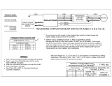
B.
CONTROLS AND INSTRUMENTATION
1) OUTPUT CONTROLS:
a) OUTPUT SELECTOR
Switch:
Adjustment
of
the output is accomplished by
the combination
of
the OUTPUT SELECTOR
Switch
and VERNIER CONTROL.
This is a multi-position switch which provides
coarse adjustment
of
the output. Position 1
provides minimum output. The last position
provides maximum output. The
OUTPUT
SELECTOR Switch
is interlocked with the
output initiating circuit. Depressing the switch
to change positions operates the interlock and
de-energizes the output.
b)
VERNIER
CONTROL Provides fine adjustment
of
the output
(Power
Stat): between steps
of
the OUTPUT SELECTOR
Switch.
2. Circuit Breaker:
3.
FUSE:
4. AUX.
OUTLET
Functions
as
the input
POWER
ON/OFF
Switch
and also provides short-circuit and
overload protection.
Protects control and isolation transformers
A ground fault protected
120-volt outlet is
provided
for
convenient connection
of
accessory equipment.
4

5.
Input Receptacles
6.
Equipment Ground
7.
Isolation Ground
Receptacles for input power connection
Test set chassis ground. For safety purposes,
this should be connected to a power system
ground.
This ground connection
is
part
of
an
interlock
circuit that verifies that the test set chassis
is
connected to a separate earth ground.
5

i
I
I
I
I
I
, !
4. DDA CONTROL PANEL
o
TEST
1.
START
Button
- Energizes the output
2.
STOP
Button
- De-energizes the output.
3.
EXT. START
Terminals
- An external switch can be plugged into these terminals
(blue) to provide remote initiation
of
the test set.
TEST FUNCTION
4. TIMER STOP MODE - Three modes
of
operation are available to control the output
and timer operation.
C.A. (Current Actuate) - When the device
to
be tested has no contacts other than
those involved
in
the passing
of
test current, this type
of
operation is used. In this
position, the timer will run from the initiation
of
the test until the test circuit is
interrupted. This position is the position most commonly used for controlling timer
operations (Default setting). The output will de-energize when the current level
drops below 8%
of
range.
N.O. (Normally Open) - When it is desired to control the timer from a set
of
normally
open contacts (such as an auxiliary contact) this type
of
operation may be used.
In
this position, the timer will run from the initiation
of
the test until the opening
of
the
contacts connected to the
TIMER STOP (Yellow) terminals.
N.C. (Normally Closed) - When it is desired to control the timer from a set
of
normally closed contacts (such as a multi-pole circuit breaker), this type
of
operation
may be used.
In this position, the
tim~r
will
run
from the initiation
of
the test until the
opening
of
the contact connected to the TIMER STOP (Yellow) terminals.
5.
TIMER STOP
Terminals
- These terminals (yellow) facilitate connection to a set
of
contacts on the device under test to monitor contact opening and closure. The timer
6

stops and output is de-energized when the device operates (used
in
conjunction
with the
TIMER STOP MODES
of
N.O. and N.C).
6.
TIME UNITS Selection- Selects the mode
of
count; either cycles
or
seconds.
7.
OUTPUT Mode - The following two selections are available
PULSE - When selected, the output
of
the test set is on for a short, specified time
period (default is 5 cycles) and then
is
turned off. (Should the device under test
operate after pushing the START Button, the output will be de-energized). This
position is
normally used when setting the test current prior to the timing test and
providing short high current pulses for instantaneous tests. However, the duration
of
this output pulse can be programmed via the Display Menu. (See the Section III,
E.
Front Panel Display and Programming Menus.) (Default Setting).
MAl NT. - When selected, and the START Button is pressed, the control circuit
maintains the output
of
the test set until the device under test operates or the STOP
Button is pressed. This is the normal position for Time Delay tests.
VOLTS (voltmeter selection) Switches
8.
VOLTS - three different selections are available for display
IN
- When this voltage display selection is made, the voltage at the input plugs
of
the
test set will be displayed (Default Setting).
OUT - When this voltage display selection is made, the voltage at the output
terminals
of
the test set will be displayed.
EXT. - When this voltage display selection is made, the voltage applied to the EXT.
VOLTS terminals will be displayed.
9.
EXT. VOLTS terminals - These two terminals enable the digital voltmeter to
measure external a.c. voltages up to
600 Volts.
AMMETER
10. AMMETER RANGE Switches - Selects the desired full scale range
of
the meter.
NOTE: The output current level from the test set must be at least 8 percent
of
any full scale value before the ammeter will indicate an output reading. Please be
aware that changing ammeter ranges while the output is energized may
result
in erroneous ammeter readings. The 4 range selections are
0.2kA1
2kA1
20kA I
and 200 kA range. Default Setting is the 200 kA range.
11.AMMETER MODE
MEM/CONT - Selects the mode
of
the ammeter circuit. In the MEM position, the
highest measured current is indicated on the ammeter.
The
CONT mode permits
7

I"
.,
[
I
I
the ammeter to continually indicate the value
of
output current. When
in
the CONT.
and MAl NT. Modes
of
operation, it will require 30 cycles
of
output current before a
current value will be displayed. Default
Setting is MEM.
SERIPAR -
When
operating the unit with the output in a series configuration, this
switch must be in the
SERIES position in order for the ammeter to read the correct
amount
of
output current. (See Section IV, 2, A for more details.) The default setting
is PARALLEL.
FRONT PANEL DISPLAY AND INDICATORS
12.
LCD Display Panel - This panel displays Output Amperage, Vac, and Time. It is
also used to program many other features
of
the DDA control panel (See Section
III,
Front Panel Display and Programming Menus
for
more details).
13.Front Panel
Indicators
Over
Range - Illuminates to indicate that output current has exceeded the
AMMETER RANGE selected.
Output Energized - Illuminates to indicate that the SCR has gated and the output is
energized.
Interlock GND Open - A special ground interlock circuit is incorporated which verifies
that the test set chassis is connected to system ground before the output
of
the test
set can be energized.
If
not properly grounded, this indicator will illuminate and
prevent the test set from energizing.
Thermal Warning -
Indicates that the thermal status
of
the test set is approaching an
over temperature condition.
Thermal Shutdown -
Indicates that the thermal status
of
the test set has reached an
over temperature condition. The test set will not operate as long as there is an over
temperature condition.
14.Softkeys - Used to set programmable functions indicated on the
LCD display panel:
8

SECTION III
1. FRONT PANEL DISPLAY AND PROGRAMMING MENUS
9

I
I
I •
; .
I ' :
I
2.
Flow
Diagram
of
Display Menus
A. METERING DISPLAY
All
of
the programmable menu options may be accessed by pressing the soft key
underneath the word MENU
in
the metering display screen. When pressed, the
following
display will appear.
B.
MAIN MENU
From the
MAIN MENU the user may select programming menus to make
adjustments to the
LCD display contrast, SCR controls,
or
Acquisition control
(current calculation method). The user may also select to EXIT back out to the
metering
display screen. The desired option would be selected by pressing the soft
key
directly beneath that option.
10

C. LCD CONTRAST MENU
The LCD
CONTRAST MENU provides two options for optimizing a user's ability to
view the display. Pressing the soft key directly beneath UP will cause the intensity
of
the display to be increased. Pressing the soft key directly beneath DOWN will
cause the intensity
of
the display to be decreased. This menu also provides the
option to return to the previous menu by pressing the soft key directly beneath
EXIT.
D.
SCR CONTROL MENU
The
SCR CONTROL MENU provides the ability to enter into two different areas
of
SCR adjustment. Pressing the soft key directly beneath PULSE DURATION will
display a menu that will
allow the user to program the number
of
cycles that the
output
of
the test set will be energized during a momentary pulse. Pressing the soft
key beneath
FIRING ANGLE will display a menu that will allow the user to program
the angle at which the output signal
of
the test set is initially energized.
E.
PULSE DURATION AND FIRING ANGLE MENUS
11

The PULSE DURATION MENU allows the user to program the number
of
cycles
that the output
of
the test set will be energized during a momentary pulse. The
number
of
cycles can be increased
or
decreased by pressing the soft keys directly
beneath UP
or
DOWN. Pressing the soft key beneath EXIT will return the user to
the previous menu. The default pulse duration setting is 5 cycles.
The
FIRING ANGLE MENU allows the user to program the initial firing angle at
which the output signal
of
the test set is energized. This is important when dealing
with asymmetrical waveforms. The more inductive the test specimen, the more
asymmetrical the output
of
the test set will be due to DC offset. Asymmetry
in
the
output
of
the test set has become
of
increased importance when performing
instantaneous trip tests on circuit breakers. By providing the ability to adjust the
firing angle
of
the test set, the user can minimize the effect
of
DC offset and
therefore collect more accurate information with regard to the instantaneous
characteristics
of
the test specimen. See ACQUISITION CONTROL MENU for
information on how to determine
if
the output
of
the test set is symmetrical and how
to adjust the firing angle if it is not. The default firing angle is
70
0
.
F.
ACQUISITION CONTROL MENU
12

The Acquisition Control MENU allows the user to select between two different
current measurement methods. By pressing the softkey
directly beneath either
PEAK
or
RMS, the user selects which calculation will be used in displaying
measured current on the metering display. PEAK measures the highest peak and
multiplies it by a constant 0.707. This method
of
measurement should initially be
compared to the
RMS measurement method (with all output setting being the same),
which is a true rms measurement.
If
the output waveform is symmetrical, the two
measurements will be approximately the same current
value.
If
these two
measurements are not approximately the same
value, adjust the firing angle
in
such
a way as to bring the two measurements
closer together.
Although
the
PEAK
and
RMS
measurement
will
never
be
the same value, the
goal
is
to
find
the
firing
angle
that
will
bring
these
two
measurements
as
close
together
as
possible
in
order
to
minimize
DC offset. See FIRING ANGLE MENU
for
adjustment
of
firing
angle. The method
of
current measurement is selected by pressing the soft key
beneath the desired method. Pressing the softkey beneath
EXIT will return the user
to the previous menu. The
default setting is PEAK.
13

SECTION IV INPUT AND OUTPUT CIRCUITS
1. INPUT:
A. INPUT VOLTAGE: The AVO International Circuit Breaker Test Sets are designed to
operate on a single phase voltage source.
If
the nominal rated voltage source
is
not
available, or if use at various locations requires the capability to operate the test set
from several different input voltages an optional input autotransformer may be used
(see Bulletin
in
Section I for description) .
. B. INPUT LEADS: The power source must have sufficient capacity to maintain RATED
input voltage at the
INPUT terminals
of
the test set. All units are supplied with
15
foot 2
10
input cables with connectors on one end. This
is
done in an effort to
provide a locking input connector, for safety purposes, along with input cables that
are appropriate for a minimal amount
of
voltage drop from the input source to the
input terminals
of
the test set. Although the test sets are designed to operate
satisfactorily at 95-105%
of
rated voltage, any drop in voltage below RATED at the
input terminals will result
in
a proportional decrease
in
the maximum available
output.
NOTE: To achieve published output currents, the rated input voltage must be
maintained at the test set terminals during the test.
C.
GROUNDING: For safety, ground wires must be connected to the test set chassis
in order to energize the test set.
One ground lead must be connected to the ground
terminal located just
belowlhe
input plug to system ground. The size
of
the
conductor should be not less than 6 AWG. Due to the special ground interlock
circuit, a second lead must be connected from the green GND binding post to a
separate, but compatible system ground. This will insure that a ground has been
achieved and allow the test set to be energized.
D.
SAFETY PRECAUTIONS:
CAUTION
For
safety
of
the operator, it is absolutely essential that the test set be properly and
effectively grounded.
2. OUTPUT:
A.
SELECTION OF OUTPUT CONNECTIONS: Two output connections, parallel
and
series, provide various voltage and current ratings to adapt AVO International Circuit
Breaker Test
Sets to a wide variety
of
test circuit impedances.
The test sets can be operated most effiCiently by utilizing the parallel connection,
which provides the
HIGHEST CURRENT rating consistent with being able to obtain
the desired test current.
In
this way, finer adjustment can be obtained by making
maximum use
of
the variable autotransformer range .. Even the smallest currents
can be obtained from the parallel connection. The series connection should be used
only when testing high impedance devices where the parallel connection does not
14
/