Page is loading ...

INSTALLATION AND SERVICE MUST BE PERFORMED BY
A QUALIFIED INSTALLER.
IMPORTANT: SAVE FOR LOCAL ELECTRICAL INSPECTOR'S USE.
READ AND SAVE THESE INSTRUCTIONS FOR FUTURE REFERENCE.
40 1/8" Min.
101.9 crn Min.
13" Min.
(45.7 crn Min.) (33 crn Min.)
\\
Grounded 24" Min.
Wall Outlet (61 cm Min.)
47 _A" Max.
(120 crn)
43 ;A"
(111.1 cm)
with larger\
door open __ _
27 3A
feet extended
(91.4 cm)
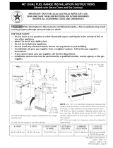
Do not pinch the power supply cord between the range
and the wall.
Do not seal the range to the side cabinets.
**NOTE: 24" (61 cm) minimum clearance between the
cooktop and the bottom of the cabinet when the bottom
of wood or metal cabinet isprotected by not lessthan
1/4" (0.64 cm) flame retardant millboard covered with not
less than No. 28 MSG sheet metal, 0.015" (0.4 mm)
stainless steel, 0.024" (0.6 mm) aluminum, or 0.020" (0.5
mm) copper.
30" (76.2 cm) minimum clearance when the cabinet is
unprotected.
36"(91.4cm) 401/8"(101.9cm) 251/2"(64.8cm) 433/4"(111.1cm) 401/4"(102.2cm) 36"(91.4cm)standard
35%" (90cm) rain.
P/N 318200870 (0201 ) Rev. E

Important Notes to the Installer
1. Read all instructions contained in these installation
instructions before installing range.
2. Remove all packing material from the oven
compartments before connecting the electrical supply to
the range.
3. Observe all governing codes and ordinances.
4. Be sure to leave these instructions with the consumer.
Important Note to the Consumer
Keep these instructions with your owner's guide for future
reference.
IMPORTANT SAFETY
INSTRUCTIONS
• Be sure your range is installed and grounded
properly by a qualified installer or service
technician.
• This range must be electrically grounded in
accordance with local codes or, in their absence,
with the National Electrical Code ANSI/NFPA No.
70--latest edition.
• The installation of appliances designed for
manufactured (mobile) home installation must conform
with Manufactured Home Construction and Safety
Standard, title 24CFR, part 3280 [Formerly the Federal
Standard for Mobile Home Construction and Safety,
title 24, HUD (part 280)] or when such standard is not
applicable, the Standard for Manufactured Home
Installation 1982 (Manufactured Home Sites,
Communities and Setups), ANSI Z225.1/NFPA 501A-
latest edition, or with local codes.
° Make sure the wall coverings around the range
can withstand the heat generated by the range.
• ALL RANGES
CAN TIR
• INJURYTO
PERSONS
COULD
RESULT.
• INSTALLANTI-
TIPDEVICE
PACKEDWITH
RANGE.
_O REDUCE
THE RISK OF TIPPING OF
THE RANGE, THE RANGE
MUST BE SECURED BY
PROPERLY INSTALLED ANTI-
TIP BRACKET(S) PROVIDED
WITH THE RANGE. TO
CHECK IF THE BRACKET(S)
IS INSTALLED PROPERLY,
REMOVE THE LOWER
PANEL OR STORAGE
DRAWER AND VERIFY THAT
THE ANTI-TIP BRACKET(S)
IS ENGAGED.
Before installing the range in an area covered
with linoleum or any other synthetic floor
covering, make sure the floor covering can
withstand heat at least 90°F/32°C above room
temperature without shrinking, warping or
discoloring. Do not install the range over carpeting
unless you place an insulating pad or sheet of 1/4" (6.4
mm) thick plywood between the range and carpeting.
_Never leave children alone or
unattended in the area where an appliance is in use.
As children grow, teach them the proper, safe use of all
appliances. Never leave the oven door open when the
range is unattended.
_Stepping, leaning or sitting on the
door(s) or drawer of this range can result in serious
injuries and can also cause damage to the range.
• Do not store items of interest to children in the
cabinets above the range. Children could be
seriously burned climbing on the range to reach items.
° To eliminate the need to reach over the surface
units, cabinet storage space above the units
should be avoided.
° Do not use the oven as a storage space. This
creates a potentially hazardous situation.
° Never use your range for warming or heating the
room. Prolonged use of the range without adequate
ventilation can be dangerous.
° Do not store or use gasoline or other flammable
vapors and liquids near this or any other
appliance. Explosions or fires could result.
• Reset all controls to the "off" position after using
a programmable timing operation.
• Save 4 shipping bolts from range packaging to
use as leveling legs for range.
Two anti-tip brackets MUST be removed from
lower back of range and MUST be installed. For
detailed instructions, see page 8.
FOR MODELS WITH SELF-CLEAN FEATURE:
• Remove broiler pan, food and other utensils
before self-cleaning the oven. Wipe up excess
spillage. Follow the precleaning instructions in the
Owner's Guide.
2

Power Supply Cord Kit
The user is responsible for connecting the power supply
cord to the connection block located behind the back
panel access cover.
This appliance may be connected by means of
permanent "hard wiring" (flexible armored or
nonmetallic shielded copper cable), or by means of a
power supply cord kit. Only a power supply cord kit
rated at 125/250 volts minimum, 40 amperes and
marked for use with ranges shall be used. Cord must
have 3 conductors (see Figures 1 and 5).
Mobile homes, new installations, recreational vehicles,
or areas where local codes do not permit grounding
through neutral, a 4 conductor power supply cord kit
rated at 125/250 volts minimum, 40 amperes and
marked for use with ranges should be used (see Figures
2 and 6).
Terminals on ends of wires must either be closed loop or
open-end spade lugs with upturned ends. Cord must
have strain relief clamp.
Risk of fire or electrical shock may be
incurred if an incorrect size range cord kit is used,
the Installation Instructions are not followed, or
the strain relief bracket is discarded.
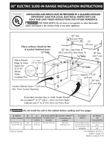
3-Wire Power
Supply Cord Kit
Figure 1
3-Wire Wall
Receptacle
If Connecting to a 4-Wire System
This range is manufactured with the ground connected to
the cabinet. The ground must be revised so the green
ground wire of the 4-wire power supply cord is
connected to the cabinet. See "Four Conductor Wire
Connection to Range" on page 4.
When a 4-wire receptacle of NEMA Type 14-50R is used
(see Figure 1), a matching U.L.-listed, 4-wire, 250 volt,
40 ampere range power supply cord (pigtail) must be
used. This cord contains 4 copper conductors with ring
terminals at the appliance end, terminating in a NEMA
Type 14-50P plug on the supply end. The fourth (ground)
conductor must be identified by a green or green/yellow
cover and the neutral conductor by a white cover. Cord
should be Type SRD or SRDT with a U.L.-listed strain
relief and be at least 4 feet long.
The minimum conductor sizes for the copper 4-wire
power cord are:
40 ampere circuit
2 No. 8 conductors
1 No. 10 white neutral
1 No. 8 green ground
[E 11
4-Wire Wall
Receptacle (14-50R)
Figure 2
Electrical Connection to the Range
This appliance is manufactured with the neutral terminal
connected to the frame.
1. Three Conductor Wire Connection to Range
(The 3-conductor cord or cable must be replaced
with a 4-conductor cord or cable where grounding
through the neutral conductor is prohibited in mew
installations, mobile homes, recreational vehicles or
in other areas where local codes do not permit
neutral grounding.)
If local codes permit connection of the frame
grounding conductor to the neutral wire of the
copper power supply cord (see Figure 4).
A. Remove the 3 screws at the lower end of the
rear wire cover, then raise the lower end of the
rear wire cover (access cover) upward to expose
range terminal connection block (see Figure 3).

TO GAUN ACCESS TO LOWER TERMUNAL BLOCK
BEND LOWER BACK COVER PLATE ALONG ROW
OF HOLES SHOWN HERE=
Figure 3
B. Remove the 3 loose nuts (after you removed the
rubber band) on the terminal block using 3/8"
nut driver or socket.
C. Connect the neutral of the copper power supply
cord to the center silver-colored terminal of the
terminal block, and connect the other wires to
the outer terminals. Math wires and terminals by
color (red wires connected to the right terminal,
black wires connected to the left terminal).
D. Lower the terminal cover and replace the 3
screws.
Silver Colored Terminal
A CONSUMER
SUPPLmEDSTRAIN-RELIEF
MUST BE INSTALLED
AT THIS LOCATION
Grounding
TO FUSED DmSCONNECT BOX OR
APPROVED WmRING DEVmCE FOR
3=WIRE COPPER POWER SUPPLY CORD (40 AMPERES)
Figure 4
Do not loosen nuts, wich secure the
factory-installed range wiring to terminal block while
connecting range. Electrical failure or loss of electrical
connection may occur.
2,
Four Conductor Wire Connection to Range
(mobile homes)
A. Remove the 3 screws at the lower end of the
rear wire cover, then raise the lower end of the
rear wire cover (access cover) upward to expose
range terminal connection block.
B. Remove the ground strap from the terminal
block and from the appliance frame. Retain the
ground screw.
C. Connect the ground wire (green) of the copper
power supply cord to the frame of the appliance
with the ground screw, using the hole in the
frame where the ground strap was removed (see
Figure 5).
D. Connect the neutral (white) wire of the copper
power supply cord to the center silver-colored
terminal of the terminal block, and connect the
other wires to the outer terminals.
E. Lower the terminal cover and replace the 3
screws.
SimverColored Terminal
A CONSUMER round
SUPPLIED STRAIN=RELIEF (Bare Coppe
MUST BE INSTALLED
AT THUS LOCATION
TO FUSED DUSCONNECT BOX OR
APPROVED WIRUNG DEVICE FOR
4=WIRE COPPER POWER SUPPLY CORD (40 AMPERES)
NOTE: BE SURE TO REMOVE THE SUPPLIED GROUNDING
Figure 5
Electrical Connection to the Residence
Electrical System
The appliance may be connected directly to the fused
disconnect or circuit breaker box through flexible,
armored or nonmetallic sheathed copper cable (with
grounding wire). Locate the junction box to allow 2 to 3
feet of slack in the line so that the range can be moved
if servicing is ever necessary. Do not cut the conduit.
A U.L.-listed conduit connector must be provided at
each end of the power supply cable (at the appliance
and at the junction box). Wire sizes (copper wire only)
and connections must conform with the rating of the
appliance.
4

Electrical Shock Hazard
• Electrical ground is required on this appliance.
• Do not connect to the electrical supply until
appliance is permanently grounded.
• Disconnect power to the junction box before
making the electrical connection.
• This appliance must be connected to a
grounded, metallic, permanent wiring system,
or a grounding connector should be connected
to the grounding terminal or wire lead on the
appliance.
Failure to do any of the above could result in a
fire, personal injury or electrical shock.
Grounding Instructions
For appliances connected to a junction box, use U.L.-
listed conduit connectors. Complete electrical connection
according to local codes and ordinances.
Where local codes permit connecting the
cabinet-grounding conductor to the neutral
(white) junction box wire (see Figure 6)
(The 3-conductor cord or cable must be replaced
with a 4-conductor cord or cable where grounding
through the neutral conductor is prohibited in mew
installations, mobile homes, recreational vehicles or
in other areas where local codes do not permit
neutral grounding.)
A. Disconnect the power supply.
B. Connect together the 3 wires: green (bare) and
white appliance cable wires and the neutral
(white) wire in the junction box.
C. Connect the 2 black wires together, then the
two red wires together.
Ground
(White Wire) [_
Red_--..,...I_'
Bare or ------si
Green Wire
CaMefrom
PowerSupply
BUack
i _Junction
Box
White Wire
_" "'_"- U.L4isted
_'_ Conduit
Cable from Connector
Range (or CSA listed)
Figure 6 - GROUNDED NEUTRAL
.
.
Where local codes DO NOT permit, or if
connecting to a 4-wire electrical system, DO
NOT connect the cabinet-grounding conductor
to the neutral (white) junction box wire (see
Figure 7)
A. Disconnect the power supply.
B. Separate the bare copper and white appliance
cable wires.
C. Connect the white appliance cable wire to the
neutral (white) wire in the junction box.
D. Connect the 2 black wires together, then the
two red wires together.
E. Connect the bare copper grounding wire to the
grounding wire in the junction box.
Junction Cable from
Conduit
Carte from Connector
Range (or CSA listed)
Figure 7 - 4-WIRE ELECTRICAL SYSTEM
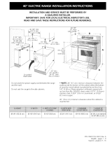
Locate junction box as shown in Figure 8.
If a service cord is used, the wall receptacle should
be located in accordance with the dimensions
below.
Figure 8

Cabinet Construction
Range Installation
_To eliminate the risk of burns or fire by
reaching over heated surface units, cabinet storage
space located above the range should be avoided. If
cabinet storage space is to be provided, the risk can be
reduced by installing a range hood that projects
horizontally a minimum of 5" (1 2.7 cm) beyond the
bottom of the cabinet.
Center
Line of
Range
I
Follow instructions for
the type of installation you have
Figure 9
If range will be installed with a cabinet on both
sides, mark center of cabinet opening on floor. If back
of range will not be flush with the wall (the location
of the outlet may not allow the range to be positioned
against the wall), mark on the floor where the back
edge of the range will be. Place the template on the
floor aligning the template centerline with the centerline
marked in the cabinet opening. Place the back edge of
the template against the rear wall or the line marked for
the rear of the range.
If range will be installed with a cabinet on one side
only, move the range into final position. Mark on the
floor along the side of the range that is not against the
cabinet. If back of range will not be flush with the
wall (the location of the outlet may not allow the range
to be positioned against the wall), mark on the floor
where the back edge of the range will be. Place the
template on the floor and align side of template with the
line marked on the floor. Align the back of the template
with the rear wall or the line marked for the rear of the
range.
If range will not be installed against a cabinet,
move range into final position. Mark on the floor along
both sides of the range. If back of range will not be
flush with the wall (the location of the outlet may not
allow the range to be positioned against the wall), mark
on the floor where the back edge of the range will be.
Place the template on the floor and align sides of
template with the lines marked on the floor. Align the
back of the template with the rear wall or the line
marked for the rear of the range.
_When unpacking the range, do not discard
the 4 shipping bolts. These are to be replaced on the
unit for use as leveling legs and height adjustments.
NOTE:
1. The back of the range may be installed directly
against the rear wall of the structure.
2. These ranges conform to U.L. requirements for "0"
spacing from the range to adjacent vertical walls
above the countertop level. However, to reduce
possible scorching of vertical walls and to minimize
potential fire hazards under abnormal surface unit
use conditions such as high heat or no pans, a
minimum of 2" (5.1 cm) spacing should be provided
on both sides of the cooktop.
Preparation
1. Put on safety glasses and gloves. Remove oven racks
and parts package from inside the oven. Remove
shipping materials, tape and protective film from the
range.
2. Take 4 cardboard corners from the carton. Stack one
on top of another. Repeat with other 2 corners.
Place corners lengthwise on the floor in back of the
range to support range.
Excessive Weight Hazard
Use 2 or more people to move and install
range.
Failure to follow this instruction can result in
back or other injury.
3. Firmly grasp the range and gently lay it on its back
on the cardboard corners.
4. Remove and save the 4 shipping bolts from the skid.
Discard skid.
5. Install 4 shipping bolts as leveling legs.
6. Place cardboard in front of the range. Carefully
stand the range upright on cardboard.
7. Adjust the leveling legs to a point where the range
base does not touch the floor.

Remove Cooktop Shipping Screws
The liftable cooktop on this range is locked down to
prevent shipping damage (see Figure 10).
1. Open both doors and locate the two shipping screws
at the front end, underneath the cooktop.
2. Remove and discard the two shipping screws using a
#2 Robertson or Phillips head screwdriver.
3. The cooktop can now be lifted, when needed.
Figure 10
Leveling the Range
Level the range and set cooktop height before
installation in the cut-out opening (if applicable).
1. Install an oven rack in the center of the oven.
2. Place a level on the rack. Take 2 readings with the
level placed diagonally in one direction and then the
other. Level the range, if necessary, by adjusting the
4 leg levelers with a wrench (see Figure 13).
3. Slide range into cut-out opening and double check
for levelness. If the range is not level, pull unit out
and readjust leveling legs, or make sure floor is level.
Figure 11
Check Operation
Refer to the Owner's Guide packaged with the range for
operating instructions and for care and cleaning of your
range.
_Do not touch the elements. They may be
hot enough to cause burns.
Remove all packaging from the oven before testing.
1. Operation of Surface Elements
Turn on each of the four surface elements and check to
see that they heat. Check the surface element indicator
light(s), if equipped.
2. Operation of Oven Elements
The oven isequipped with an electronic oven control. Each
of the functions has been factory checked before shipping.
However, it issuggested that you verify the operation of the
electronic oven controls once more. Refer to the Owner's
Guide for operation. Follow the instructions for the Clock,
Timer, Bake, Broil, Convection (some models) and Clean
(some models) functions.
Bake-After setting the oven to 350% (177°C) for
baking, the lower element in the oven should become
red.
Broil-When the oven is set to BROIL, the upper element
in the oven should become red.
Clean (some models)-When the oven is set for a self-
cleaning cycle, the upper element should become red
during the preheat portion of the cycle. After reaching
the self-cleaning temperature, the lower element will
become red.
Convection (some models)-When the oven is set to
CONV. BAKE/ROAST at 350% (177°C), both elements
cycle on and off alternately and the convection fan will
turn. The convection fan will stop turning when the oven
door is opened during convection baking or roasting.
When All Hookups are Complete
Make sure all controls are left in the OFFposition.
Model and Serial Number Location
The serial plate is located on the oven front frame
behind the large oven door.
When ordering parts for or making inquiries about your
range, always be sure to include the model and serial
numbers and a lot number or letter from the serial plate
on your range.
Before You Call for Service
Read the Avoid Service Checklist and operating
instructions in your Owner's Guide. It may save you time
and expense. The list includes common occurrences that
are not the result of defective workmanship or materials
in this appliance.
Refer to the warranty and service information in your
Owner's Guide for our phone number and address.
Please call or write if you have inquiries about your
range product and/or need to order parts.

Important Safety Warning
To reduce the risk of tipping of the range, the range
must be secured to the floor by properly installed anti-tip
brackets and screws packed with the range. Those parts
are located in a plastic bag in the oven. Failure to install
the anti-tip brackets will allow the range to tip over if
excessive weight is placed on an open door or if a child
climbs upon it. Serious injury might result from spilled
hot liquids or from the range itself.
Follow the instructions below to install the anti-tip
brackets.
If range is ever moved to a different location, the anti-tip
brackets must also be moved and installed with the
range. To check for proper installation, see step 5.
Tools Required:
5/16" (8 mm) Nutdriver or Flat Head Screwdriver
Adjustable Wrench
Electric Drill
3/16" (4.8 ram) Diameter Drill Bit
3/16" (4.8 ram) Diameter Masonry Drill Bit (if installing
in concrete)
Anti-Tip Brackets Installation Instructions
Brackets attach to the floor at the back of the range to
hold both rear leg levelers. When fastening to the floor,
be sure that screws do not penetrate electrical wiring or
plumbing. The screws provided will work in either wood
or concrete.
1. Unfold paper template and place it flat on the floor
with the back and side edges positioned exactly
where the back and sides of range will be located
when installed. (Use the diagram below to locate
brackets if template is not available.)
2. Mark on the floor the location of the 4 mounting
holes shown on the template. For easier installation,
3/16" (4.8 ram) diameter pilot holes 1/2" (1.3 cm)
deep can be drilled into the floor.
3. Remove template and place brackets on floor with
turned up flanges to the front. Line up holes in
brackets with marks on floor and attach with 4
screws provided. Brackets must be secured to solid
floor. If attaching to concrete floor, first drill 3/16"
(4.8 mm) dia. pilot holes using a masonry drill bit.
4. Level range if necessary, by adjusting 4 leg levelers
with wrench. (See Figure 13 below.) A minimum
clearance of 1/8" (3.2 mm) is required between the
bottom of the range and the rear leg levelers to
allow room for the anti-tip brackets.
5. Slide range into place making sure rear legs are
trapped by ends of brackets. Range may need to be
shifted slightly to one side as it is being pushed back
to allow rear legs to align with brackets. You may
also grasp the top rear edge of the range and
carefully attempt to tilt it forward to make sure
range is properly anchored.
SUDE
BACK
ANTFTIp
BRACKE_
3/4"
(1.9 cm)
Figure 12 Figure 13
/