Edision FURM35000A Smartvest Wireless Smoke / Heat Detector User manual

Category
Security device components
Type
User manual
Back to Contents 1 Back to Contents
Smartvest
User manual
You can find important information and FAQs about this and other
products online at:
www.abus.com
Version 1.4 English translation of the original German user manual.
Retain for future reference.
Back to Contents 2 Back to Contents
English
Introduction
Dear Customer,
Thank you for purchasing this product.
This device complies with the requirements of the applicable EU directives. The declaration of
conformity can be obtained from:
ABUS Security-Center GmbH & Co. KG
Linker Kreuthweg 5
86444 Affing
GERMANY
To ensure this condition is maintained and that safe operation is guaranteed, it is your obligation to
observe this user manual.
Please read the entire user manual carefully before putting the product into operation, and pay attention
to all operating instructions and safety information.
All company names and product descriptions are trademarks of the corresponding owner. All
rights reserved.
If you have any questions, please contact your specialist installation contractor or specialist
dealer.
Disclaimer
This user manual has been produced with the greatest of care. Should you discover any omissions
or inaccuracies, please contact us in writing at the address provided above.
ABUS Security-Center GmbH does not accept any liability for technical and typographical errors, and
reserves the right to make changes to the product and user manuals at any time and without prior
warning.
ABUS Security-Center GmbH is not liable or responsible for direct or indirect damage resulting from
the equipment, performance and use of this product. No guarantee is made for the contents of this
document.
Back to Contents 3 Back to Contents
English
Explanation of symbols
The triangular high voltage symbol is used to warn of the risk of injury or health
hazards (e.g. caused by electric shock).
The triangular warning symbol indicates important notes in this user manual which
must be observed.
This symbol indicates special tips and notes on the operation of the device.
Lists
1. …
2. … Lists with a set order, given either in the text or warning notice
• …
• … Lists without a set order, given either in the text or warning notice
Intended use
Only use the device for the purpose for which it was built and designed. Any other use is considered
unintended!
This device may only be used for the following purpose(s):
• The Smartvest wireless alarm system enables easy access to modern homes with its
combination of reliable all-round security and attractive home-automation functions. Up to 32
wireless components and four IP cameras can be connected to the Smartvest alarm panel via
the free app, enabling you to access the alarm panel from anywhere in the world. If an alarm is
triggered, the alarm panel activates its built-in, high-volume 90 dB siren; it can also raise the
alarm simultaneously via push notifications in the app and email.
Important safety information
General
Before using this device for the first time, please read the following instructions carefully and observe
all warning information, even if you are familiar with the use of electronic devices.
All guarantee claims are invalid in the event of damage caused by non-compliance
with this user manual. We cannot be held liable for resulting damage.
We cannot be held liable for material or personal damage caused by improper
operation or non-compliance with the safety information. All guarantee claims are
void in such cases.
Retain this handbook for future reference.
If you sell or pass on the device to third parties, you must include these instructions with the device.
The following safety information and hazard notes are not only intended to protect your health, but also
to protect the device from damage. Please read the following points carefully:
Back to Contents 4 Back to Contents
English
Power supply
• Only operate this device using a power source which supplies the grid voltage specified on the
type plate. If you are unsure which power supply is available, contact your utility company.
• Disconnect the device from the power supply before carrying out maintenance or installation work.
• To fully disconnect the device completely from the mains, the mains plug must be withdrawn from
the mains socket.
• In order to eliminate the risk of fire, the device's mains plug should always be disconnected from
the mains socket, if the device is not being used for an extended period of time.
Overload/overvoltage
• Prior to unstable weather and/or when there is a risk of lightning strike, disconnect the device from
the mains network or connect the device to a UPS.
• Avoid overloading electrical sockets, extension cables and adapters, as this can result in fire or
electric shock.
Cable
• Always grasp all cables by the plug connector and do not pull the cable itself.
• Never grasp the power cable with wet hands, as this can cause a short circuit or electric shock.
• Do not place the device itself, items of furniture or other heavy objects on the cable and ensure
that it does not become kinked, especially at the connector plug and at the connection sockets.
• Never tie a knot in the cable and do not bundle it together with other cables.
• All cables should be laid so that they cannot be trodden on, or cause a hazard.
• Damaged power cables can cause fire or electric shock. Check the power cable from time to time.
• Do not modify or manipulate the power cable or plug.
• Only use adapter plugs or extension cables that conform to applicable safety standards, and do
not interfere with the mains or power cables.
Children
• Do not allow electrical devices to be handled by children. Do not allow children to use electrical
devices unsupervised. Children may not properly identify possible hazards. Small parts may be
fatal if swallowed.
• Keep packaging film away from children. Risk of suffocation.
• This device is not intended for children. If used incorrectly, parts under spring tension may fly out
and cause injury to children (e.g to eyes).
Back to Contents 5 Back to Contents
English
Installation location/operating environment
Place or mount the device on a steady, level surface and do not place any heavy objects on the device.
Make sure that there is adequate ventilation (do not place the Smartvest on a shelf, thick carpet, bed
or wherever the ventilation slits may be covered. Always leave a gap of at least 10 cm on all sides).
The Smartvest is not designed for operation in rooms prone to high temperatures or humidity (e.g.
bathrooms) or excessive dust accumulation.
For all components only suitable for indoor use, please ensure that
• no direct heat sources (e.g. radiators) have an effect on the components
• the components are not exposed to direct sunlight or strong artificial light
• no naked flames (e.g. lit candles) are placed on or next to the components
• contact with sprayed or dripping water is avoided
• the components are not operated in the vicinity of water and, in particular, never submerged (do
not place objects containing fluids, e.g. vases or drinks on or near the device)
• the components are not exposed to large temperature fluctuations, as otherwise there may be
condensation from humidity which may lead to electrical short circuits
For all components that are suitable for indoor and outdoor use, please ensure that
• the components are not exposed to excessive shock or vibration
• the components are not placed in the immediate vicinity of magnetic fields (e.g. loudspeakers)
• contact with aggressive liquids is avoided
• no foreign objects are able to penetrate the components
• the operating temperature and operating humidity of the components are observed.
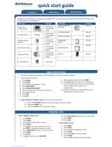
Please refer to the relevant quick guide, technical information and installation instructions in chapter 3
for information on proper installation and compliance with the operating environment for components.
Battery
All Smartvest components, with the exception of power switches, are or can be supplied with a battery.
In order to guarantee a long lifespan and avoid fire and injury, please follow the instructions below:
• Do not dispose of the battery with household waste.
• The battery must not be directly exposed to heat or sunlight, and must not be stored in hot places.
• The battery must not be burned.
• The battery must not come into contact with water.
• The battery must not be dismantled, pierced or otherwise damaged.
• The battery contacts must not be short-circuited.
• The battery must be kept away from small children.
• The battery cannot be recharged.
Back to Contents 6 Back to Contents
English
Unpacking the device
Handle the device with extreme care when unpacking it.
Packaging and packaging aids can be reused and, as far as possible, should be sent for recycling.
We recommend the following:
Paper, cardboard and corrugated cardboard as well as plastic packaging items should be placed in the
appropriate recycling containers.
If no such facility exists in the area, these materials should be put into the general household waste.
Warning
If the original packaging has been damaged, start by inspecting the device. If the device
shows signs of damage, return it in the original packaging and inform the delivery service.
Start-up
Observe all safety and operating instructions before operating the device for the first time.
Warning
Improper or unprofessional work on the power supply system or domestic installations
puts both you and others at risk.
Connect the installations so that the mains power circuit and low-voltage circuit always run
separately from each other. They should not be connected at any point or become
connected as a result of a malfunction.
Care and maintenance
Maintenance is necessary if the device has been damaged (e.g. damage to the power cable and plug,
or the housing), or if liquids or foreign bodies have got into the interior of the device, or if it has been
exposed to rain or damp, or if it does not work properly or has been dropped.
Maintenance
• If smoke, unusual noises or smells develop, switch the device off immediately and unplug from
the socket. In such cases, the device should not be used until it has been inspected by a qualified
technician.
• Have all maintenance tasks carried out by qualified technicians only.
• Never open the housing on the device or accessories. If the housing is open, there is the risk of
fatal electric shock.
Cleaning
• Only clean the device housing with a damp cloth.
• Do not use solvents, white spirit, thinners etc. or any of the following substances:
Brine, insect spray, solvents containing chlorine or acids (ammonium chloride), or scouring
powder.
• Rub the surface gently with the cotton cloth until it is completely dry.
The device operates with a dangerous voltage level. When conducting maintenance
work (e.g. cleaning), disconnect the device from the mains.
Back to Contents 7 Back to Contents
English
Contents
1. Device description ........................................................................................................................... 9
2. Start-up .......................................................................................................................................... 20
3. Installation ...................................................................................................................................... 28
4. Operation ....................................................................................................................................... 37
5. Configuration ................................................................................................................................. 48
6. Smartvest Feature Update ............................................................................................................ 69
Back to Contents 8 Back to Contents
English
7. Technical data ............................................................................................................................... 73
8. FURM35000 Smartvest Wireless Smoke/Heat Detector............................................................... 78
Back to Contents 9 Back to Contents
English
1. Device description
This chapter contains descriptions of the Smartvest and all associated components.
FUAA35000 Smartvest
Front
1 Power LED Green On System is supplied with power
Off No power supply
2 Status LED
Off System is "disarmed"
Yellow On The system is "disarmed" and there is a fault
(e.g. battery dead or magnetic contact is "open")
Blue On System is "armed"
Red On System is "armed" and in the alarm state
(normal alarm, tamper alarm or panic alarm)
3 Network LED
Green On Connection to network and internet
Off Connection to network without internet
Red Flashing No network connection
4 Optional stand. Removable for wall installation.
1
4
2
3
Back to Contents 10 Back to Contents
English
Under side
1 Reset button
To reset passwords to the default settings (123456) and network settings
to DHCP:
• While the system is in operation, press and hold the reset button for
>10 seconds using a paper clip. The power LED will go out and a
continuous tone will sound. The system then restarts.
Resetting the system to the default settings means that all settings are reset
and component pairings are deleted.
• Press the reset button with the alarm control panel turned off, and
hold it for >10 seconds while turning on the alarm control panel. The
power LED will go out and a continuous tone will sound. The system
then restarts.
2 RJ45 connector Integrated network access 10/100 Mbit
3 Power supply 5 V DC/1.5 A. Device starts automatically when powered by line voltage.
4 Hygrometer Integrated hygrometer for measuring temperature and humidity
1
4
3
Back to Contents 11 Back to Contents
English
Rear
1 Battery
operation
6 x AA (1.5 V) batteries for backup power supply (approx. 5h battery life)
Changing the battery
Push the clips to open the battery compartment cover.
Remove the dead 6 AA (1.5 V) batteries from the compartment and replace
with the new 6 AA (1.5 V) batteries. Make sure they are facing in the direction
shown on the compartment floor, then close the battery compartment by
replacing the cover.
2 Mounting
bracket Mounting bracket for wall installation
Drill hole spacing: 10 cm (drilling template provided)
3 Loudspeaker Smartvest loudspeaker with a maximum volume of 90db.
4 Background
LEDs
Off Off System is "disarmed"
Yellow On The system is "disarmed" and there is a fault
(e.g. battery dead or magnetic contact is "open")
Blue On System is "armed"
Red On System is "armed" and in the alarm state
(e.g. magnetic contact open).
5 Cabling Cabling for power supply and network cable.
1
4
2
3
5
Back to Contents 12 Back to Contents
English
FUHA35000 Power Switch
1 Schuko socket Schuko socket type F (CEE 7/4). Can be used in the following countries:
Germany, Austria, Sweden, Netherlands
2 Status LED
Off
Power switch is activated; power is being
transmitted.
Blue On Power switch is ready and activated; power is not
being transmitted to the appliance.
Flashing Power switch is starting up
Orange
Flashing Repeater mode started
On
Power switch is ready and activated; power is not
being transmitted to the appliance.
Repeater mode on and connected with a
component.
3 Button Press this button once to activate or deactivate the power switch.
Press and hold the button for five seconds, to activate repeater mode.
4 Schuko socket Schuko socket type F (CEE 7/4). Can be used in the following countries:
Germany, Austria, Sweden, Netherlands
Repeater mode
As well as switching appliances, the power switch can also be used as a wireless repeater for another
component. To do this, take the following steps:
1. Press and hold the button for five seconds to activate repeater mode. The status LED will start to
flash orange.
2. For any components that you want to connect to the power switch, carry out the manual process
for pairing components (see chapter 5, Configuration).
3. The status LED lights up orange when the connection is successful
4. To deactivate repeater mode again, first disconnect the switch. Press and hold the button.
Reconnect the switch. Wait until the LED flashes blue and only then release the button. If
deactivation was successful, the LED will now light up blue.
Note
It is only ever possible to connect one component to a power switch.
1
2
3
4
Back to Contents 13 Back to Contents
English
FUMK35000 magnetic contact
1 Transmitter
component Contains a wireless component
Mounted on window frame
2 Signal LED Blue Flashing Magnetic contact is closed
Magnetic contact is opened
3 Battery
operation
1x 3 V button battery (CR2032) for power supply (up to one year battery life).
The Smartvest App warns you when the battery is low. Follow the instructions
in the app.
Changing the battery
Slide the battery compartment cover out in a downwards direction.
Remove the dead 3 V button batteries from the holder provided and replace
with a new 3 V battery, then close the battery compartment by replacing the
cover.
4 Magnet
component Contains a magnet component
Mounted on window
1
2
3
4
Back to Contents 14 Back to Contents
English
FUBW35000 PIR Motion Detector
1 Catch Catch for removing the rear panel
2 Pair button Button for manual pairing with the Smartvest
Activate test mode: press for 5 s
Deactivate test mode: press for 5 s
3 Tampering
contact Tampering contact for alarming in the event of unwanted removal
4 Battery
operation
3 x AA (1.5 V) batteries for power supply (up to two years battery life)
The Smartvest App warns you when the battery is low. Follow the instructions
in the app.
Changing the battery
Press the catch on the underside of the PIR Motion Detector and remove the
rear panel. Remove the 3 dead AA (1.5 V) batteries from the compartment
and replace with 3 new AA (1.5 V) batteries. Make sure they are facing in the
direction shown on the compartment floor, Reattach the PIR Motion Detector
to the mounted rear panel.
Note
In test mode, the PIR Motion Detector's energy-saving mode is deactivated so it triggers
each time motion is detected. Use this to check whether the detector fully covers the
monitored space. Deactivate test mode after use, as otherwise this will severely affect the
battery life.
FURM35000 smoke alarm/heat detector
Refer to the instructions for the smoke alarm/heat detector.
(pls also refer to chapter 8. FURM35000 Smartvest Wireless Smoke/Heat Detector)
1
2
3
4
Back to Contents 15 Back to Contents
English
FUSG35000 siren
1 LED chamber LED flashes (according to
setting) in the event of an alarm and to
acknowledge changes to the siren settings.
2 Loudspeaker Siren loudspeaker with a maximum volume of 80 db or 100 db.
3 Pair button Button for manual pairing with the Smartvest
4 Tampering
contact Tampering contact for alarming in the event of unwanted removal
5 Battery
operation
4 x C (1.5 V) batteries for power supply (up to two years battery life)
Changing the battery
Loosen both screws on the cover. You do not need to completely remove the
screws. Lift the cover upwards from the bottom and remove.
In order to access the screws more easily when changing the batteries, you
can temporarily remove the tampering contact's rubber cover.
Remove the dead 4 C (1.5 V) batteries from the compartment and replace
with the new 4 C (1.5
V) batteries. Make sure that the battery is always
positioned with the negative end against the spring. Place the top end of the
cover into the holes provided and attach the cover beneath using the two
screws.
1
2
3
4
5
Back to Contents 16 Back to Contents
English
FUBE35000 Remote Key
1 Signal LED Blue Flashing Acknowledges when button is pressed
2 Arm button Button for arming the Smartvest
Press and hold for five seconds to part set
3 Disarm button Button for disarming the Smartvest
4 Camera button Button to start recording for connected cameras
5 Panic button Button for triggering the panic alarm (press for 3 seconds)
6 Battery
operation
1x 3 V button battery (CR2032) for power supply (up to two years battery life)
The Smartvest App warns you when the battery is low. Follow the instructions
in the app.
Changing the battery
Remove the battery compartment on the side of the Remote Key.
Remove the dead 3 V button batteries from the holder provided and replace
with a new 3 V battery, Push the battery compartment back into the Remote
Key.
Note
The exact reaction caused when a button is pressed depends on the app settings. Refer
to Section 5.7, Advanced settings for the arm and disarm buttons, and Section 5.4,
Hotkeys for the camera button and panic button.
1
2
3
4
5
6
Back to Contents 17 Back to Contents
English
FUBE35010 Control panel
1 Arm button Button for arming the Smartvest
2 Disarm button Button for disarming the Smartvest Verification is required after pressing (PIN
or RFID Chip).
3 Part
set button Button for part setting the Smartvest.
4 Panic button Button for triggering the panic alarm (press and hold for five seconds).
5 Settings button Button for settings options. Verification is required after pressing (PIN code).
6 RFID reader
Signal LED Blue Flashing
RFID reader has now been active for 30 seconds
and is awaiting verification.
7 Mount
slot These square slots are for fixing the control panel to the mount.
8 Battery
operation
4 x AA (1.5 V) batteries for power supply (up to one year battery life)
The Smartvest App warns you when the battery is low. Follow the instructions
in the app.
Changing the battery
Once you have set the alarm panel to maintenance mode, remove the
control panel from the mount by lightly pressing the tab at the bottom of the
mount downwards. You can now slide the control panel out from above.
Loosen the screws on the back and open the battery compartment.
Remove the 4 dead AA (1.5 V) batteries from the compartment and replace
with 4 new AA (1.5 V) batteries. Make sure the polarity is correct when
replacing the batteries.


1
2
3
4
5
6
9
10
11
12
Back to Contents 18 Back to Contents
English
9 Reset button
Resets the control panel to the default settings, i.e. all settings are reset, and
the PIN code and all paired RFID chips are unpaired.
• Press and hold the control panel's reset button for > 5 seconds during
operation. Two consecutive signal tones will sound to confirm reset.
The control panel will then restart.
• The default PIN code is (1234), no RFID chips are paired. Please
ensure that the control panel is still paired in your Smartvest system.
10 Tampering
contact Tampering contact for alarming in the event of unwanted removal
11 Cabling
Cabling for the power supply
12 Sounder
Control panel sounder
Note
The exact reaction caused when a button is pressed depends on the app settings. Refer
to Section 5.7, Advanced settings for the arm and disarm buttons, and Section 5.4,
Hotkeys for the panic button.
Note
An exit delay of 30 seconds is preset on the control panel. When pressing the arm/part
set button, the Smartvest will only be armed/part set once this time has elapsed.
You can increase the exit delay to a total of 60 seconds by adjusting the exit delay for
arm/part set under Status configuration in the app's advanced settings (see Section 5.7).
– Please note that, in this case, the exit delay will remain set to 30 seconds for arming/part
setting via app and Remote Key.
The exit delay set on the control panel can be cancelled by pressing the disarm button.
Operation
Arming the system
Press the button to arm the system. Once the button has been pressed, an exit delay begins which
arms the system after 30 seconds. A signal tone sequence with decreasing intervals (crescendo)
indicates that arming is imminent.
Part setting the system
Press the button to part set the system. Once the button has been pressed, an exit delay begins
which part sets the system after 30 seconds. A signal tone sequence with decreasing intervals
(crescendo) indicates that arming is imminent.
Disarming the system
Press the button to part set the system. Once the button has been pressed, you have 30 seconds
for verification using a four-digit PIN code or RFID chip (see Section 5.2 "Pairing"). Please hold the RFID
chip in front of the blue flashing LED. Successful verification is indicated by two consecutive signal
tones.
Triggering a panic alarm
To trigger a panic alarm, press and hold the button for > five seconds.
Back to Contents 19 Back to Contents
English
FUWM35000 Waterleak Detector
1 Wallmount-
Holes The waterleak detector housing is fixed on the wall on this holes.
2 Battery-Case
4x AA (1,5 V) Batteries for power-supply (up to 2 Years Battery-Lifetime)
The Smartvest App receives a Trouble in case of Low Battery. Pls. follow the
instruction in the App
Battery change:
Once you have set the Alarm-
Panel to Maintenance mode, take the
Waterleak detector from the wall. Open the battery-case, remove the empty
4 x AA (1.5V) Batteries and insert the fresh 4 x AA (1.5V) Batteries instead.
Pls. pay attention for the correct polarity.
3 Mute Button In case of an Alarm, you may mute the siren of the Waterleak-detector here.
4 Pairing-Button Button for pairing the Detector with the Smartvest
5 Sensor-socket Socket to plug in the Waterleak sensor.
6 Siren
In case of an alarm, the siren of the Waterleak detector sounds 5 minutes
Operation
Mute the Siren of the Waterleak detector
In case of an alarm, the siren sounds for 5 minutes. You may mute the siren by pushing the mute button.
In case of repeated-alarm, the Siren sounds again.
3
5
2
4
1
Back to Contents 20 Back to Contents
English
2. Start-up
Before installing your Smartvest and detector, follow the steps below to start up your Smartvest and
pair components with the Smartvest.
Installing the Smartvest App
For the Smartvest, there is an app called "Smartvest" available for
download from the Google Play Store and the iOS App Store. This
app can be used on smartphones and tablets, referred to as "end
devices" from this point on.
For installation, go to the Google Play Store or the iOS App Store
and search for "Smartvest".
Install the Smartvest App.
Note
Please note that the following operating systems are
minimum requirements for running the Smartvest
App:
Apple iOS 8
Android 4.0
Setting up the Smartvest
First connect the LAN cable provided on the underside of the
Smartvest and connect this to your router,
then connect the power supply unit provided.
Note
Ensure that the DHCP function is activated on your
router as otherwise it will not be possible to connect
to the Smartvest.
Only start setting up the Smartvest via the app when
the green power LED lights up continuously and the
alarm panel beeps twice.
There is no double beep sound if integrated into a
local network without Internet access.
  • Page 1 1
  • Page 2 2
  • Page 3 3
  • Page 4 4
  • Page 5 5
  • Page 6 6
  • Page 7 7
  • Page 8 8
  • Page 9 9
  • Page 10 10
  • Page 11 11
  • Page 12 12
  • Page 13 13
  • Page 14 14
  • Page 15 15
  • Page 16 16
  • Page 17 17
  • Page 18 18
  • Page 19 19
  • Page 20 20
  • Page 21 21
  • Page 22 22
  • Page 23 23
  • Page 24 24
  • Page 25 25
  • Page 26 26
  • Page 27 27
  • Page 28 28
  • Page 29 29
  • Page 30 30
  • Page 31 31
  • Page 32 32
  • Page 33 33
  • Page 34 34
  • Page 35 35
  • Page 36 36
  • Page 37 37
  • Page 38 38
  • Page 39 39
  • Page 40 40
  • Page 41 41
  • Page 42 42
  • Page 43 43
  • Page 44 44
  • Page 45 45
  • Page 46 46
  • Page 47 47
  • Page 48 48
  • Page 49 49
  • Page 50 50
  • Page 51 51
  • Page 52 52
  • Page 53 53
  • Page 54 54
  • Page 55 55
  • Page 56 56
  • Page 57 57
  • Page 58 58
  • Page 59 59
  • Page 60 60
  • Page 61 61
  • Page 62 62
  • Page 63 63
  • Page 64 64
  • Page 65 65
  • Page 66 66
  • Page 67 67
  • Page 68 68
  • Page 69 69
  • Page 70 70
  • Page 71 71
  • Page 72 72
  • Page 73 73
  • Page 74 74
  • Page 75 75
  • Page 76 76
  • Page 77 77
  • Page 78 78
  • Page 79 79
  • Page 80 80
  • Page 81 81
  • Page 82 82
  • Page 83 83
  • Page 84 84
  • Page 85 85
  • Page 86 86

Edision FURM35000A Smartvest Wireless Smoke / Heat Detector User manual

Category
Security device components
Type
User manual

Ask a question and I''ll find the answer in the document

Finding information in a document is now easier with AI