
NOTE: DIAGRAMS & ILLUSTRATIONS ARE NOT TO SCALE.
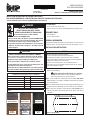
Firebox Liner Kits
for Montebello See-Through Gas Fireplaces (All Models)
Description Cat. No. Model
Ceramic, Architectural Stone H7946 BLK-ARCH-LSM40ST
Ceramic, Black Rustic H8291 BLK-B-LSM40ST
Ceramic, Buff Herringbone H7943 BLK-H-LSM40ST
Ceramic, Buff Rustic H7942 BLK-R-LSM40ST
Ceramic, Venetian Tile H7947 BLK-VT-LSM40ST
Porcelain, Black H7948 BLK-BP-LSM40ST
Table 1
KIT CONTENTS
• (2) ea. Firebox Liner Panels, Side
• (10) ea. #10-16 x 3/8" Screws (provided with porcelain panels only)
REQUIRED TOOLS
• 5/16" Nut Driver
• Scissors or Box Cutters
GENERAL INFORMATION
Each panel kit contains two ceramic or porcelain panels, one for each side
wall of the firebox. The ceramic panels have brick-like features in relief.
INSTALLATION INSTRUCTIONS
Step 1. Remove firebox liner panels (and screws, if installing porcelain
panels) from packaging.
NOTICE: Handle panels with extreme care, to prevent
damage. Ceramic panels are easily scratched, cracked or
broken. Porcelain panels are easily scratched.
Step 2. If not already done, remove glass door assembly from control
side of fireplace. See fireplace Installation Instructions for complete
door removal details.
Step 3. Cut and discard the nylon securing the grate and boxed log set to
the firebox. Remove boxed log set, and set aside for later installation.
Step 4. Using a 5/16" nut driver, remove the top air baffle (Figure 1) from
the top of the firebox by removing four screws (two on each side of
the baffle.
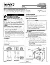
HEARTH PRODUCTS
KITS AND ACCESSORIES
FIREBOX LINER PANELS
Montebello™ and DRT/DRC6300 See-Through Gas Fireplaces
INSTALLATION INSTRUCTIONS FOR FIREBOX LINER PANELS
FOR USE WITH MONTEBELLO™ AND DRT/DRC6300 SERIES SEE-THROUGH GAS FIREPLACES
(FOR USE WITH MODELS DRT63STTEN/TEP/TYN AND MONTEBELLOSTTEN/TEP/TYN)
P/N 506020-46
Rev. NC 10/2014
Ceramic:
Architectural Stone
Ceramic:
Buff Rustic
Ceramic:
Buff Herringbone
Ceramic:
Venetian Tile
Ceramic:
Black Rustic
Porcelain:
Black
NOTICE
•Readallstepsbeforestartinginstallation.
•Theseinstructionsmustbeleftwiththeappliance.
•Allwarnings,precautions,andinstructionsintheInstallation
Instructions and Care and Operation Instructions provided with the
appliance also apply to these instructions.
•Ifyouencounteranyproblems,needclaricationofthese
instructions, or are not qualified to properly install this kit, contact
your local distributor or dealer.
CAUTION
RISK OF PERSONAL INJURY OR PROPERTY DAMAGE.
•Never operate fireplace without a firebox liner panel kit installed.
These appliances are NOT approved for operation without liner panels.
•Do NOT abuse glass doors by striking or slamming shut
•Never operate fireplace with glass door assemblies removed.
•Securely tighten door latch screws when reinstalling glass door
assemblies to prevent doors from falling out.
• Handle glass door assemblies with extreme care. Replace damaged
glass door assemblies with approved replacement assemblies only.
WARNING
HOT GLASS WILL CAUSE BURNS.
DO NOT TOUCH GLASS UNTIL COOLED.
NEVER ALLOW CHILDREN TO TOUCH GLASS.
• Install only when fireplace is OFF and COLD.
• Fireplace surfaces get EXTREMELY HOT!
• The glass on the front of the fireplace reaches EXTREMELY HIGH
temperatures and can cause severe burns if touched. Even after the
gas is turned off, fireplace surfaces remain extremely hot.
• Keep children away from an operating fireplace. Closely supervise
children in any room where a fireplace is operating to prevent
contact with glass.
P506020-46
Figure 1: Top Air Baffle
Slots

Figure 4
Top Corner Notch
~
~
Side Panel
(ceramic
panel
shown)
Printed in U.S.A. © 2014 Innovative Hearth Products
P/N 506020-46 Rev. NC 10/2014
Innovative Hearth Products reserves the right to make
changes at any time, without notice, in design, materi-
als, specifications, and prices, and also to discontinue
colors, styles, and products. Consult your local
distributor for fireplace code information.
NOTE: DIAGRAMS & ILLUSTRATIONS ARE NOT TO SCALE.
1508 Elm Hill Pike, Suite 108
Nashville, TN 37210
IHP.us.com
Figure 2
Firebox with one Floor Bracket removed
Step 6. Set aside floor bracket and screws for later reinstallation. (Figure
2 shows firebox with one floor bracket removed.)
INNOVATIVEHEARTHPRODUCTS•SEE-THROUGHDIRECT-VENTGASFIREPLACES•FIREBOXLINERPANELKITINSTALLATION
Step 7. Using a 5/16" nutdriver, remove L-bracket at top of firebox wall
(on same side as bracket just removed). (One L-bracket is shown in
Figure 5).
For ceramic panel installation: Set aside L-bracket and screw for later
reinstallation.
For porcelain panel installation: Discard
L-bracket and screw.
Step 8. Install one side panel, as follows:
a) Hold panel with top corner notches UP,
(see Figure 3).
b) Insert panel into firebox at an angle (as
shown in Figure 4), taking care not to
scratch or damage the panel.
c) Carefully push panel up against side wall
of firebox (it may be necessary to lift up panel while positioning it).
Step 5. Starting on either side of firebox, use a 5/16" nutdriver to remove
the two screws securing the floor bracket (Figure 1), and then remove
the floor bracket.
Figure 5
L-bracket at top of Side Wall
(one bracket on each side)
Step 9. Follow applicable steps for panel type being installed:
CERAMIC PANELS: Reinstall L-bracket at top of side wall (see Figure
5). Go to Step 10.
PORCELAIN PANELS: Using a 5/16" nutdriver, attach panel to top of
firebox with (3) screws and to floor of firebox with (2) screws.
(Note: Firebox may already have screws where porcelain panels are
to attach that need to be removed first. Either reuse those screws
or use the 10 provided screws to attach the panels.)
Step 10. Insert previously removed floor bracket into firebox. Slide floor
bracket up against side panel, taking care not to scratch or damage
panel. Align holes in floor bracket with holes in firebox floor. Reattach
floor bracket to firebox floor with two previously removed screws.
Step 11. Repeat Steps 5–10 to install the other side panel.
Step 12. Reinstall the top air baffle, as follows:
a) Loosely install (do not tighten) two previously removed screws
for air baffle on side of fireplace opposite the control side.
b) Hook the two open slots in the air baffle (see Figure 1) over the
two screws, but do not tighten screws yet.
c) Attach other side of air baffle to firebox top with the other two
previously removed screws.
d) Tighten all four air baffle screws.
P506020-46
Figure 3
Top Corner
Notches of
Side Panel
Figure 1
~
Firebox Wall
Floor Bracket
(one on each side of firebox)
(2) Screws per
Floor Bracket
-
 1
1
-
 2
2


Astria Fireplaces MONTEBELLO ST Instruction Sheet
- Type
- Instruction Sheet
- This manual is also suitable for
Ask a question and I''ll find the answer in the document
Finding information in a document is now easier with AI
Related papers
-
Astria Fireplaces Montebello Instruction Sheet
-
-
-
-
-
-
-
-
-
Other documents
-
Superior Fireplaces DRT63ST Operating instructions
-
-
Lennox Hearth LSM40ST-N User manual
-
-
-
-
 Lennox Hearth LSM40ST User manual
-
 Astria Montebello DLX Operating instructions
-
-
 Lennox Hearth 875027M User manual


