Motorola CP040 Basic Service Manual
- Category
- Two-way radios
- Type
- Basic Service Manual

Commercial Series
CP040 Portable Radio
Basic Service Manual
6866549D14-A
Issue: October 2004

ii
Computer Software Copyrights
The Motorola products described in this manual may include copyrighted Motorola computer programs stored
in semiconductor memories or other media. Laws in the United States and other countries preserve for
Motorola certain exclusive rights for copyrighted computer programs, including the exclusive right to copy or
reproduce in any form, the copyrighted computer program. Accordingly, any copyrighted Motorola computer
programs contained in the Motorola products described in this manual may not be copied or reproduced in
any manner without the express written permission of Motorola. Furthermore, the purchase of Motorola
products shall not be deemed to grant, either directly or by implication, estoppel or otherwise, any license
under the copyrights, patents or patent applications of Motorola, except for the normal non-exclusive
royalty-free license to use that arises by operation of law in the sale of a product.

iii
SAFETY INFORMATION
Read this information before using the radio.
PRODUCT SAFETY AND RF EXPOSURE FOR PORTABLE TWO-WAY RADIOS.
This document provides information and instructions for the safe and efficient operation of Motorola
Portable Two-Way Radios.
The information provided in this document supersedes information
contained in user guides published prior to February 2002.
RF Energy Exposure Awareness and Control Information and Operational
Instructions for Occupational Use
Note:This Radio is intended for use in occupational/controlled applications, where users have been
made aware of the potential for exposure and can exercise control over their exposure. This radio
device is NOT authorized for general population, consumer or similar use.
This two-way radio uses electromagnetic energy in the radio frequency (RF) spectrum to provide
communications between two or more users over a distance. It uses radio frequency (RF) energy or
radio waves to send and receive calls. RF energy is one form of electromagnetic energy. Other forms
include, but are not limited to, sunlight and x-rays. RF energy, however, should not be confused with
these other forms of electromagnetic energy, which when used improperly, can cause biological
damage. Very high levels of x-rays, for example, can damage tissues and genetic material.
Experts in science, engineering, medicine, health, and industry work with organizations to develop
standards for safe exposure to RF energy. These standards provide recommended levels of RF
exposure for both workers and the general public. These recommended RF exposure levels include
substantial margins of protection.
All Motorola two-way radios are designed, manufactured, and tested to ensure they meet
government-established RF exposure levels. In addition, manufacturers also recommend specific
operating instructions to users of two-way radios. These instructions are important because they
inform users about RF energy exposure and provide simple procedures on how to control it.
Please refer to the following websites for more information on what RF energy exposure is and how to
control your exposure to assure compliance with established RF exposure limits:
http://www.fcc.gov/oet/rfsafety/rf-faqs.html
http://www.osha.gov/SLTC/radiofrequencyradiation/index.html
Federal Communication Commission (FCC) Regulations (US markets only)
The FCC rules require manufacturers to comply with the FCC RF energy exposure limits for portable
two-way radios before they can be marketed in the U.S. When two-way radios are used as a
consequence of employment, the FCC requires users to be fully aware of and able to control their
exposure to meet occupational requirements. Exposure awareness can be facilitated by the use of a
product label directing users to specific user awareness information. Your Motorola two-way radio has
a RF Exposure Product Label. Do not remove this RF Exposure Label from the device. Also, your
Motorola user manual, or separate safety booklet includes information and operating instructions
required to control your RF exposure and to satisfy compliance requirements.

iv
Compliance with RF Exposure Standards
Your Motorola two-way radio is designed and tested to comply with a number of national and
International standards and guidelines (listed below) for human exposure to radio frequency
electromagnetic energy. This radio complies with the IEEE (FCC) and ICNIRP exposure limits for
occupational/controlled RF exposure environments at operating duty factors of up to 50% talk-
50% listen and is authorized by the IEEE/ICNIRP for occupational use only.
In terms of measuring RF energy for compliance with these exposure guidelines, your radio
generates measurable RF energy only while it is transmitting (during talking), not when it is
receiving (listening) or in standby mode.
Note: The approved batteries, supplied with this radio, are rated for a 5-5-90 duty cycle (5% talk–5%
listen–90% standby), even though this radio complies with IEEE/ICNIRP occupational exposure limits
at usage factors of up to 50% talk.
Your Motorola two-way radio complies with the following RF energy exposure standards and
guidelines:
● United States Federal Communications Commission, Code of Federal Regulations; 47 CFR part 2
sub-part J
● American National Standards Institute (ANSI) / Institute of Electrical and Electronic Engineers
(IEEE) C95. 1-1992
● Institute of Electrical and Electronic Engineers (IEEE) C95.1-1999 Edition
● International Commission on Non-Ionizing Radiation Protection (ICNIRP) 1998
● Ministry of Health (Canada) Safety Code 6. Limits of Human Exposure to Radiofrequency
Electromagnetic Fields in the Frequency Range from 3 kHz to 300 GHz, 1999
● Australian Communications Authority Radiocommunications (Electromagnetic Radiation - Human
Exposure) Standard 2003
● ANATEL ANNEX to Resolution No. 303 of July 2, 2002 "Regulation of limitation of exposure to
electrical, magnetic and electromagnetic fields in the radio frequency range between 9 KHz and
300 GHz" and "Attachment to resolution # 303 from July 2, 2002"
RF Exposure Compliance and Control Guidelines and Operating Instructions
To control your exposure and ensure compliance with the occupational/controlled environment expo-
sure limits, always adhere to the following procedures:
Guidelines:
● User awareness instructions should accompany device when transferred to other users.
● Do not use this device if the operational requirements described herein are not met.
Operating Instructions
● Transmit no more than the rated duty factor of 50% of the time. To transmit (talk), push the Push-To-
Talk (PTT) button. To receive calls, release the PTT button.
Transmitting 50% of the time, or less, is important because this radio generates measurable RF
energy exposure only when transmitting (in terms of measuring for standards compliance).
● When worn on the body, always place the radio in a Motorola-approved clip, holder, holster, case,
or body harness for this product. Using approved body-worn accessories is important because the
use of non-Motorola-approved accessories may result in exposure levels, which exceed the IEEE/
ICNIRP occupational/controlled environment RF exposure limits.
● If you are not using a body-worn accessory and are not using the radio in the intended use position,
along side the head in the phone mode (TETRA only), in front of the face in the hand held mode,
then ensure the antenna and the radio are kept 2.5 cm (one inch) from the body when transmitting.
Keeping the radio at a proper distance is important because RF exposures decrease with
increasing distance from the antenna.

v
Hand-held Mode - Operating Instructions
● Hold the radio in a vertical position in front of the face with the microphone (and other
parts of the radio including the antenna) at least 2.5 cm (one inch) away from the nose or
lips. Antenna should be kept away from the eye. Keeping the radio at a proper distance is
important since RF exposures decrease with increasing distance from the antenna.
Phone Mode (TETRA only) - Operating Instructions
● When placing or receiving a phone call, hold your radio product as you would a wireless telephone.
Speak directly into the microphone.
Approved Accessories
● Use only Motorola-approved supplied or replacement antennas, batteries, and accessories. Use of
non–
Motorola - approved antennas, batteries and accessories may exceed IEEE/ICNIRP RF exposure
guidelines.
For a list of Motorola-approved antennas, batteries, and other accessories please see your dealer
or local Motorola contact. Your nearest dealer can be found at the following web site:
http://www.motorola.com/cgiss/emea/dealerlocator.html
Additional Information
For additional information on exposure requirements or other training information, visit
http://www.motorola.com/rfhealth.

vi
ELECTROMAGNETIC INTERFERENCE/COMPATIBILITY
NOTE: Nearly every electronic device is susceptible to electromagnetic interference (EMI) if
inadequately shielded, designed or otherwise configured for electromagnetic compatibility.
Facilities
To avoid electromagnetic interference and/or compatibility conflicts, turn off your radio in any facility
where posted notices instruct you to do so. Hospitals or health care facilities may be using equipment
that is sensitive to external RF energy.
Aircraft
When instructed to do so, turn off your radio when on board an aircraft. Any use of a radio must be in
accordance with applicable regulations per airline crew instructions.
Medical Devices
Pacemakers
The Advanced Medical Technology Association (AdvaMed) recommends that a minimum separation
of 15 cms (6 inches) be maintained between a handheld wireless radio and a pacemaker.These
recommendations are consistent with those of the U.S. Food and Drug Administration.
Persons with pacemakers should:
● ALWAYS keep the radio more than 15 cms from their pacemaker when the radio is turned ON.
● Not carry the radio in the breast pocket.
● Use the ear opposite the pacemaker to minimize the potential for interference.
● Turn the radio OFF immediately if you have any reason to suspect that interference is taking place.
Hearing Aids
Some digital wireless radios may interfere with some hearing aids. In the event of such interference,
you may want to consult your hearing aid manufacturer to discuss alternatives.
Other Medical Devices
If you use any other personal medical device, consult the manufacturer of your device to determine if
it is adequately shielded from RF energy. Your physician may be able to assist you in obtaining this
information.
Use of Communication Devices While Driving
Always check the laws and regulations on the use of radios in the areas where you drive.
● Give full attention to driving and to the road.
● Use hands-free operation, if available.
● Pull off the road and park before making or answering a call, if driving conditions or regulations so
require.

vii
OPERATIONAL WARNINGS
Vehicles with an air bag
Refer to vehicle manufacturer's manual prior to installation of electronic equipment to avoid
interference with air bag wiring.
Potentially explosive atmospheres
(Explosive atmospheres refers to hazard classified locations that may contain hazardous gas,
vapors, or dusts.)
Blasting caps and areas
OPERATIONAL CAUTIONS
Antennas
Batteries
WARNING: Do not place a portable radio in the area over an air bag or in the air bag
deployment area. Air bags inflate with great force. If a portable radio is placed in the air bag
deployment area and the air bag inflates, the radio may be propelled with great force and
cause serious injury to occupants of the vehicle.
WARNING: Turn off your radio prior to entering any area with a potentially explosive
atmosphere, unless it is a radio type especially qualified for use in such areas as
"Intrinsically Safe" (for example, Factory Mutual, CSA, UL, CENELEC or ATEX Approved). Do
not remove, install, or charge batteries in such areas. Sparks in a potentially explosive
atmosphere can cause an explosion or fire resulting in bodily injury or even death.
NOTE
The areas with potentially explosive atmospheres referred to above include fuelling areas such as
below decks on boats, fuel or chemical transfer or storage facilities, areas where the air contains
chemicals or particles, such as grain, dust or metal powders. Areas with potentially explosive
atmospheres are often but not always posted.
WARNING: To avoid possible interference with blasting operations, turn off your radio when
you are near electrical blasting caps, in a blasting area, or in areas posted:
"Turn off two-way radio". Obey all signs and instructions.
CAUTION: Do not use any portable radio that has a damaged antenna. If a damaged antenna
comes into contact with your skin, a minor burn can result.
CAUTION: All batteries can cause property damage and/or bodily injury such as burns if a
conductive material such as jewellery, keys, or beaded chains touch exposed terminals. The
conductive material may complete an electrical circuit (short circuit) and become quite hot.
Exercise care in handling any charged battery, particularly when placing it inside a pocket,
purse, or other container with metal objects.
!
!
!
!
!

viii
INTRINSICALLY SAFE RADIO INFORMATION
The Intrinsically safe approval unit refers to a product that has been approved as intrinsically safe by
an approval agency (for example FM Approvals, CSA, UL, CENELEC or ATEX) and certifies that a
particular product meets the Agency's applicable intrinsic safety standards for specific types of
hazardous classified locations. A portable radio that has been approved for intrinsic safety will have
Approval label attached to the radio to identify the unit as being Approved for specified hazardous
atmospheres. This label specifies the hazardous Class/Division/Group along with the part number of
the battery that must be used. The Intrinsically Safe Approval Label will be located on the portable
radio unit.
Operational Cautions for Intrinsic Safe Equipment
Warnings for Radios Approved as Intrinsically Safe
Radios must ship from the Motorola manufacturing facility with the hazardous atmosphere capability
and the intrinsic safety approval labelling (FM, UL, CSA, CENELEC or ATEX). Radios will not be
upgraded to this capability and labeled once they have been shipped to the field.
A modification changes the unit’s hardware from its original design configuration. Modifications can
only be made by the original product manufacturer.
● Do not operate radio communications equipment in a hazardous atmosphere unless it is a
type especially qualified (for example, FM, UL, CSA, or
CENELEC or ATEX approved). An
explosion or fire may result.
● Do not operate a radio unit that has been approved as intrinsically safe product in a
hazardous atmosphere if it has been physically damaged (for example, cracked housing).
An explosion or fire may result.
● Do not replace or charge batteries in a hazardous atmosphere. Contact sparking may
occur while installing or removing batteries and cause an explosion or fire.
● Do not replace or changeaccessories in a hazardous atmosphere. Contact sparking
may occur while installing or removing accessories and cause an explosion or fire.
● Turn the radio off before removing or installing a battery or accessory.
● Do not disassemble an intrinsically safe product in any way that exposes the
internal circuits of the unit.
● Failure to use an intrinsically safe approved battery or Approved accessories
specifically approved for the radio unit may result in the dangerously unsafe
condition of an unapproved radio combination being used in a hazardous location.
● Unauthorized or incorrect modification of the intrinsically safe approved Product
will negate the approval rating of the product.
● Incorrect repair or relabeling of any intrinsically safe Agency-approved radio could
adversely affect the Approval rating of the unit.
● Use of a radio that is not intrinsically safe in a hazardous atmosphere could result
in serious injury or death.
!
!

ix
Repair
A repair constitutes something done internally to the unit that would bring it back to its original
condition.
Items not considered as repairs are those in which an action is performed on a unit which does not
require the outer casing of the unit to be opened in a manner which exposes the internal electrical
circuits of the unit.
Do Not Substitute Options or Accessories
The Motorola communications equipment certified as intrinsically safe by the approving agency, (FM,
UL, CSA, CENELEC or ATEX) is tested as a complete system which consists of the listed agency
Approved portable, Approved battery, and Approved accessories or options, or both. This Approved
portable and battery combination must be strictly observed. There must be no substitution of items,
even if the substitute has been previously Approved with a different Motorola communications
equipment unit. Approved configurations are listed by the Approving Agency (FM, UL, CSA,
CENELEC or ATEX).
The Intrinsically Safe Approval Label affixed to radio refers to the intrinsically safe classification of that
radio product, and the approved batteries that can be used with that system.
The manual PN referenced on the Intrinsically Safe Approval Label identifies the approved
Accessories and or options that can be used with that portable radio unit.
Using a non Motorola intrinsically safe battery and or accessory with the Motorola approved radio unit
will void the intrinsically safe approval of that radio unit.
REPAIRS FOR MOTOROLA PRODUCTS WITH INTRINSICALLY SAFE APPROVAL ARE
THE RESPONSIBILITY OF THE USER.
● Repairs to a Motorola FM approved radio product should only be done at a location
that has been FM audited under the FM 3605 repairs and service standard.
● Contact Motorola for assistance regarding repairs and service of Motorola
intrinsically safe equipment.
!

x

xi
Table of Contents
SAFETY INFORMATION........................................................................................iii
Chapter 1 INTRODUCTION
1.0 Scope of Manual ..................................................................................................1-1
2.0 Warranty and Service Support.............................................................................1-1
2.1 Warranty Period and Return Instructions .......................................................1-1
2.2 After Warranty Period .....................................................................................1-1
2.3 European Radio Support Centre (ERSC).......................................................1-2
2.4 Piece Parts .....................................................................................................1-2
2.5 Technical Support...........................................................................................1-3
3.0 Radio Model Information......................................................................................1-4
Chapter 2 MAINTENANCE
1.0 Introduction ..........................................................................................................2-1
2.0 Preventive Maintenance ......................................................................................2-1
2.1 Inspection .......................................................................................................2-1
2.2 Cleaning Procedures ......................................................................................2-1
3.0 Safe Handling of CMOS and LDMOS Devices ....................................................2-2
4.0 Repair Procedures and Techniques — General ..................................................2-3
5.0 Disassembling and Reassembling the Radio — General ....................................2-3
6.0 Radio Disassembly - Detailed..............................................................................2-4
6.1 Front Cover from Chassis Disassembly .........................................................2-4
6.2 Dust Cover Disassembly ................................................................................2-6
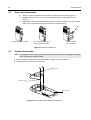
6.3 Speaker Disassembly.....................................................................................2-6
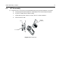
6.4 PTT Disassembly ...........................................................................................2-7
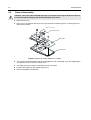
6.5 Chassis Disassembly .....................................................................................2-8
7.0 Radio Assembly - Detailed...................................................................................2-9
7.1 Chassis Assembly/Reassembly .....................................................................2-9
7.2 PTT-Assembly ................................................................................................2-9
7.3 Speaker Assembly........................................................................................2-10
7.4 Dust Cover Assembly ...................................................................................2-10
7.5 Chassis and Front Cover Assembly .............................................................2-11
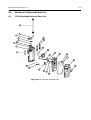
8.0 Mechanical View and Parts Lists .......................................................................2-13
8.1 CP040 Exploded View and Parts List...........................................................2-13
9.0 Service Aids .......................................................................................................2-15
10.0 Test Tools and Equipment .................................................................................2-16
11.0 Programming/Test Cable ..................................................................................2-17
12.0 Wiring of the Connectors ...................................................................................2-17

xii
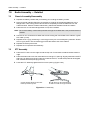
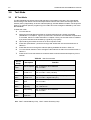
Chapter 3 TRANSCEIVER PERFORMANCE TESTING
1.0 General ................................................................................................................3-1
2.0 Setup ...................................................................................................................3-1
3.0 Test Mode ...........................................................................................................3-2
3.1 RF Test Mode ................................................................................................3-2
Chapter 4 RADIO TUNING AND PROGRAMMING
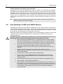
1.0 Introduction ..........................................................................................................4-1
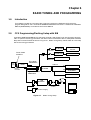
2.0 CPS Programming/Flashing Setup with RIB .......................................................4-1
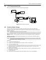
3.0 CPS Programming Setup ....................................................................................4-2
4.0 Radio to Radio Cloning........................................................................................ 4-2
Chapter 5 POWER UP SELF-TEST
1.0 Self-Test Routine .................................................................................................5-1
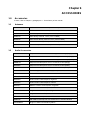
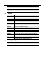
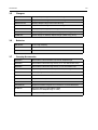
Chapter 6 ACCESSORIES
1.0 Accessories .........................................................................................................6-1
1.1 Antennas ........................................................................................................6-1
1.2 Audio Accessories..........................................................................................6-1
1.3 Headsets ........................................................................................................6-2
1.4 Remote Speaker Microphone.........................................................................6-2
1.5 Chargers.........................................................................................................6-3
1.6 Batteries .........................................................................................................6-3
1.7 Carrying Accessories ..................................................................................... 6-3
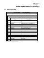
Chapter 7 MODEL CHART AND SPECIFICATION
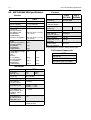
1.0 Model Chart VHF1 136-162 MHz ........................................................................7-1
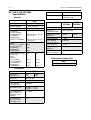
2.0 VHF1 136-162 MHz Specifications......................................................................7-2
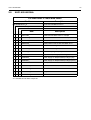
3.0 Model Chart VHF2 146-174 MHz ........................................................................7-3
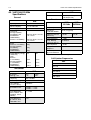
4.0 VHF 146-174 MHz Specifications........................................................................7-4
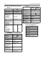
5.0 Model Chart UHF1 403-440MHz .........................................................................7-5
6.0 UHF1 403-440 MHz Specifications......................................................................7-6
7.0 Model Chart UHF2 438-470 MHz ........................................................................7-7
8.0 UHF2 438-470 MHz Specifications......................................................................7-8
9.0 Model Chart UHF3 465-495 MHz ........................................................................7-9
10.0 UHF3 465-495 MHz Specifications....................................................................7-10
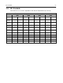
11.0 MIL Standards ..................................................................................................7-12
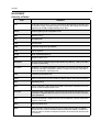
GLOSSARY...................................................................................................................... 1

Chapter 1
INTRODUCTION
1.0 Scope of Manual
This manual is intended for use by service technicians familiar with similar types of equipment. It
contains service information required for the equipment described and is current as of the printing
date. Changes which occur after the printing date may be incorporated by a complete Manual
revision or alternatively as additions.
2.0 Warranty and Service Support
Motorola offers long term support for its products. This support includes full exchange and/or repair
of the product during the warranty period, and service/ repair or spare parts support out of warranty.
Any "return for exchange" or "return for repair" by an authorised Motorola Dealer must be
accompanied by a Warranty Claim Form. Warranty Claim Forms are obtained by contacting an
Authorised Motorola Dealer.
2.1 Warranty Period and Return Instructions
The terms and conditions of warranty are defined fully in the Motorola Dealer or Distributor or
Reseller contract. These conditions may change from time to time and the following notes are for
guidance purposes only.
In instances where the product is covered under a "return for replacement" or "return for repair"
warranty, a check of the product should be performed prior to shipping the unit back to Motorola.
This is to ensure that the product has been correctly programmed or has not been subjected to
damage outside the terms of the warranty.
Prior to shipping any radio back to the appropriate Motorola warranty depot, please contact
Customer Resources (Please see page 2 and page 3 in this Chapter). All returns must be
accompanied by a Warranty Claim Form, available from your Customer Services representative.
Products should be shipped back in the original packaging, or correctly packaged to ensure no
damage occurs in transit.
2.2 After Warranty Period
After the Warranty period, Motorola continues to support its products in two ways.
1. Motorola's Radio Aftermarket and Accessory Division (AAD) offers a repair service to both
end users and dealers at competitive prices.
2. AAD supplies individual parts and modules that can be purchased by dealers who are
technically capable of performing fault analysis and repair.
NOTE
Before operating or testing these units, please read the Safety Information Section in the
front of this manual.

1-2 INTRODUCTION
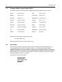
2.3 European Radio Support Centre (ERSC)
The ERSC Customer Information Desk is available through the following service numbers:
Austria: 08 00 29 75 41 Italy: 80 08 77 387
Belgium: 08 00 72 471 Luxemburg: 08 00 23 27
Denmark: 80 88 05 72 Netherlands: 08 00 22 45 13
Finland: 08 00 11 49 910 Norway: 80 01 11 15
France: 08 00 90 30 90 Portugal: 08 00 84 95 70
Germany: 08 00 18 75 240 Spain: 90 09 84 902
Greece: 00 80 04 91 29 020 Sweden: 02 07 94 307
UK : 08 00 96 90 95 Switzerland: 08 00 55 30 82
Ireland: 18 00 55 50 21 Iceland: 80 08 147
Or dial the European Repair and Service Centre:
Tel: +49 30 6686 1555
Please use these numbers for repair enquiries only.
2.4 Piece Parts
Some replacement parts, spare parts, and/or product information can be ordered directly. If a
complete Motorola part number is assigned to the part, it is available from Motorola Radio
Aftermarket and Accessory Division (AAD). If no part number is assigned, the part is not normally
available from Motorola. If the part number is appended with an asterisk, the part is serviceable by
Motorola Depot only. If a parts list is not included, this generally means that no user-serviceable
parts are available for that kit or assembly.
All part orders should be directed to :
Motorola GmbH
Customer Care
Am Borsigturm 130
13507 Berlin
Germany.

Warranty and Service Support 1-3
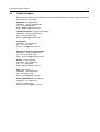
2.5 Technical Support
Motorola Product Services is available to assist the dealer/distributors in resolving any malfunctions
which may be encountered.
UK/Ireland - Richard Russell
Telephone: +44 (0) 1256 488 082
Fax: +44 01256 488 080
Email: BRR001@email.mot.com
Central/East Europe - Siggy Punzenberger
Telephone: +49 (0) 6128 70 2342
Fax: +49 (0) 6128 95 1096
Email: TFG003@email.mot.com
Scandinavia
Telephone: +46 8 735 9282
Fax: +46 8 735 9280
Email: C14749@email.mot.com
Germany -Customer Connect Team
Telephone: +49 (0) 30 6686 1539
Fax: +49 (0) 30 6686 1916
Email: [email protected]
France - Lionel Lhermitte
Telephone: +33 1 6929 5722
Fax: +33 1 6929 5904
Email: [email protected]
Italy - Ugo Gentile
Telephone: +39 0 2822 0325
Fax: +39 0 2822 0334
Email: C13864@email.mot.com
Africa & Middle East - Armand Roy
Telephone: +33 1 6929 5715
Fax: +33 1 6929 5778
Email: armand.roy@Motorola.com

1-4 INTRODUCTION
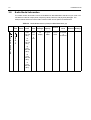
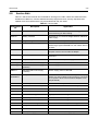
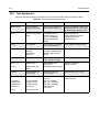
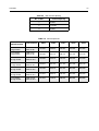
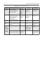
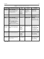
3.0 Radio Model Information
The model number and serial number are located on a label attached to the back of your radio. You
can determine the RF output power, frequency band, protocols, and physical packages. The
example below shows one mobile radio model number and its specific characteristics.
Table 1-1 Radio Model Number (Example: MDH50KDC9AA2_N)
Type of
Unit
Model
Series
Freq.
Band
Power
Level
Physical
Packages
Channel
Spacing
Protocol
Feature
Level
Model
Revision
Model
Package
MD H 50 J
VHF1
(136-162
MHz)
K
VHF
(146-174
MHz)
Q
UHF1
(403-440
MHz)
R
UHF2
(438-470
MHz)
S
UHF3
(465-495
MHz)
D
4W or
5W
C
2W
C
No
Display
9
Program-
mable
AA
Conven-
tional
1
4 channel
2
16 channel
AN
MD = Motorola Internal Use
H = Portable

Chapter 2
MAINTENANCE
1.0 Introduction
This chapter provides details about the following:
❑ Preventive maintenance (inspection and cleaning).
❑ Safe handling of CMOS and LDMOS devices.
❑ Disassembly and reassembly of the radio.
❑ Repair procedures and techniques.
2.0 Preventive Maintenance
The radios do not require a scheduled preventive maintenance program; however, periodic visual
inspection and cleaning is recommended.
2.1 Inspection
Check that the external surfaces of the radio are clean, and that all external controls and switches
are functional. It is not recommended to inspect the interior electronic circuitry.
2.2 Cleaning Procedures
The following procedures describe the recommended cleaning agents and the methods to be used
when cleaning the external and internal surfaces of the radio. External surfaces include the front
cover and housing assembly. These surfaces should be cleaned whenever a periodic visual
inspection reveals the presence of smudges, grease, and/or grime.
The only recommended agent for cleaning the external radio surfaces is a 0.5% solution of a mild
dishwashing detergent in water. The only factory recommended liquid for cleaning the printed circuit
boards and their components is isopropyl alcohol (70% by volume).
Cleaning External Plastic Surfaces
Apply the 0.5% detergent-water solution sparingly with a stiff, non-metallic, short-bristled brush to
work all loose dirt away from the radio. Use a soft, absorbent, lintless cloth or tissue to remove the
solution and dry the radio. Make sure that no water remains entrapped near the connectors, cracks,
or crevices.
NOTE
Internal surfaces should be cleaned only when the radio is disassembled for service or
repair.
CAUTION: The effects of certain chemicals and their vapors can have harmful results on
certain plastics. Avoid using aerosol sprays, tuner cleaners, and other chemicals.
!

2-2 MAINTENANCE
Cleaning Internal Circuit Boards and Components
Isopropyl alcohol (100%) may be applied with a stiff, non-metallic, short-bristled brush to dislodge
embedded or caked materials located in hard-to-reach areas. The brush stroke should direct the
dislodged material out and away from the inside of the radio. Make sure that controls are not soaked
with alcohol. Do not use high-pressure air to hasten the drying process since this could cause the
liquid to collect in unwanted places. After completing of the cleaning process, use a soft, absorbent,
lintless cloth to dry the area. Do not brush or apply any isopropyl alcohol to the frame, front cover, or
top cover.
3.0 Safe Handling of CMOS and LDMOS Devices
Complementary metal-oxide semiconductor (CMOS) devices are used in this family of radios, and
are susceptible to damage by electrostatic or high voltage charges. Damage can be latent, resulting
in failures occurring weeks or months later. Therefore, special precautions must be taken to prevent
device damage during disassembly, troubleshooting, and repair.
Handling precautions are mandatory for CMOS circuits and are especially important in low humidity
conditions. DO NOT attempt to disassemble the radio without first referring to the following
CAUTION statement.
NOTE
Always use a fresh supply of alcohol and a clean container to prevent contamination by
dissolved material (from previous usage).
CAUTION: This radio contains static-sensitive devices. Do not open the radio unless you are
properly grounded. Take the following precautions when working on this unit:
❑ Store and transport all CMOS devices in conductive material so that all exposed
leads are shorted together. Do not insert CMOS devices into conventional plastic
“snow” trays used for storage and transportation of other semiconductor devices.
❑ Ground the working surface of the service bench to protect the CMOS device. We
recommend using the Motorola Static Protection Assembly (part number
0180386A82), which includes a wrist strap, two ground cords, a table mat, and a
floor mat.
❑ Wear a conductive wrist strap in series with a 100k resistor to ground.
(Replacement wrist straps that connect to the bench top covering are Motorola part
number 4280385A59)
❑ Do not wear nylon clothing while handling CMOS devices.
❑ Do not insert or remove CMOS devices with power applied. Check all power
supplies used for testing CMOS devices to be certain that there are no voltage
transients present.
❑ When straightening CMOS pins, provide ground straps for the apparatus used.
❑ When soldering, use a grounded soldering iron.
❑ If at all possible, handle CMOS devices by the package and not by the leads. Prior
to touching the unit, touch an electrical ground to remove any static charge that you
may have accumulated. The package and substrate may be electrically common. If
so, the reaction of a discharge to the case would cause the same damage as
touching the leads.
!

Repair Procedures and Techniques — General 2-3
4.0 Repair Procedures and Techniques — General
Parts Replacement and Substitution
When damaged parts are replaced, identical parts should be used. If the identical replacement part
is not locally available, check the parts list for the proper Motorola part number and order the part
from the nearest Motorola Parts centre listed in the “Piece Parts” section in Chapter 1 of this manual.
Rigid Circuit Boards
This family of radios uses bonded, multi-layer, printed circuit boards. Since the inner layers are not
accessible, some special considerations are required when soldering and unsoldering components.
The printed-through holes may interconnect multiple layers of the printed circuit. Therefore, exercise
care to avoid pulling the plated circuit out of the hole.
When soldering near the connectors, potentiometers and circuit components:
❑ Avoid accidentally getting solder in the connector.
❑ Be careful not to form solder bridges between the connector pins.
❑ Examine your work closely for shorts due to solder bridges.
5.0 Disassembling and Reassembling the Radio — General
Since these radios may be disassembled and reassembled with the use of only four (board to
casting) screws, it is important to pay particular attention to the snaps and tabs, and how parts align
with each other.
The following tools are required for disassembling/assembling the radio:
❑ Small flat blade screwdriver
❑ knob remover/chassis opener
❑ TORX™ T6 screwdriver
If a unit requires more complete testing or service than is customarily performed at the basic level,
send this unit to a Motorola Authorized Service Centre. (See Chapter 1 for a list of authorized
service centres.)
The following disassembly procedures should be performed only if necessary:
❑ Speaker Disassembly (Figure2-5)
❑ PTT Disassembly (Figure 2-6)
❑ Chassis Disassembly (Figure 2.7)

2-4 MAINTENANCE
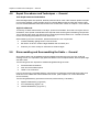
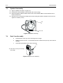
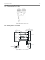
6.0 Radio Disassembly - Detailed
6.1 Front Cover from Chassis Disassembly
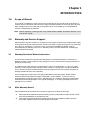
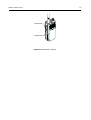
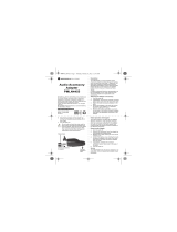
1. Turn off the radio.
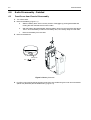
2. Remove the battery (Figure 2-1) :
a. Slide the battery latch into the unlock position. Disengage by pushing downward and
holding the latch towards the front of the radio.
b. With the battery latch disengaged, slide the battery down from the top of the radio about
15mm. Once the battery is free from the battery rails, lift it directly away from the radio.
c. Remove the battery from the radio.
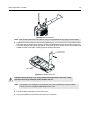
3. Remove the antenna.
4. Pry off the volume and channel selector knobs from their shafts using the knob remover/chassis
opener tool (Motorola part No.6686533Z01) (Figure 2.2).
Figure 2-1 Battery Removal
Battery Latch
Lock
Unlock
Page is loading ...
Page is loading ...
Page is loading ...
Page is loading ...
Page is loading ...
Page is loading ...
Page is loading ...
Page is loading ...
Page is loading ...
Page is loading ...
Page is loading ...
Page is loading ...
Page is loading ...
Page is loading ...
Page is loading ...
Page is loading ...
Page is loading ...
Page is loading ...
Page is loading ...
Page is loading ...
Page is loading ...
Page is loading ...
Page is loading ...
Page is loading ...
Page is loading ...
Page is loading ...
Page is loading ...
Page is loading ...
Page is loading ...
Page is loading ...
Page is loading ...
Page is loading ...
Page is loading ...
Page is loading ...
Page is loading ...
Page is loading ...
Page is loading ...
Page is loading ...
Page is loading ...
Page is loading ...
Page is loading ...
Page is loading ...
Page is loading ...
Page is loading ...
Page is loading ...
Page is loading ...
-
 1
1
-
 2
2
-
 3
3
-
 4
4
-
 5
5
-
 6
6
-
 7
7
-
 8
8
-
 9
9
-
 10
10
-
 11
11
-
 12
12
-
 13
13
-
 14
14
-
 15
15
-
 16
16
-
 17
17
-
 18
18
-
 19
19
-
 20
20
-
 21
21
-
 22
22
-
 23
23
-
 24
24
-
 25
25
-
 26
26
-
 27
27
-
 28
28
-
 29
29
-
 30
30
-
 31
31
-
 32
32
-
 33
33
-
 34
34
-
 35
35
-
 36
36
-
 37
37
-
 38
38
-
 39
39
-
 40
40
-
 41
41
-
 42
42
-
 43
43
-
 44
44
-
 45
45
-
 46
46
-
 47
47
-
 48
48
-
 49
49
-
 50
50
-
 51
51
-
 52
52
-
 53
53
-
 54
54
-
 55
55
-
 56
56
-
 57
57
-
 58
58
-
 59
59
-
 60
60
-
 61
61
-
 62
62
-
 63
63
-
 64
64
-
 65
65
-
 66
66


Motorola CP040 Basic Service Manual
- Category
- Two-way radios
- Type
- Basic Service Manual
Ask a question and I''ll find the answer in the document
Finding information in a document is now easier with AI
Related papers
-
Motorola GM338 User manual
-
Motorola CP160 Detailed Service Manual
-
 Giant Electronics Talkabout T6525 User manual
-
-
-
-
Motorola CP200 Basic Service Manual
-
-
Motorola GP380 Series Basic Service Manual
-

Other documents
-
 EleTab Height Adjustable Standing Desk Sit to Stand Gas Spring Riser Converter 37 inches Tabletop Workstation fits Dual Monitor User manual
-
VocoPro VHF-MODULE (VM-1) Owner's manual
-
Hyundai HWP-220 User manual
-
Fluke Calibration PPC4 Instruction Sheet
-
Rugged Radios G1 User guide
-
 AkkuPoint 999237 User manual
-
 Northfield Telecommunications HD-1000 User manual
-
 Motorola Solutions PMLN4455 User guide
-
Bell Magnefusion Upgrade User manual
-
DeLOCK 61779 Datasheet


