Page is loading ...

CONTENTS
Chapter 1…………………..Description
Chapter 2…………………..Installation
Chapter 3…………………..Operation
Chapter 4…………………..Omega Viewer
Chapter 5…………..………Specifications

1
Chapter 1
Description
The DP470V is designed as a fully programmable
digital process indicator and miniature datalogger. The unit
will accept either 0-10 Vdc or 4-20 mA input and is fully
scalable from –999 to +9999 display counts. Scaling and
decimal point placement is selectable through the front panel
keys. PROGRAM (P) and PROCESS (L) status are indicated
by a green, .4" seven segment LED located to the right of the
main display.
The displays are 0.56" in-line red LED type. The
menu driven display prompts and 14-segment alphanumeric
characters make programming simple. A single dash (-)
displayed at the left of the readout indicates a negative
reading. Positive readings are inferred (no dash displayed).
Overload is indicated by an 'OL' on the display. Plus OL
(+OL) indicates a positive over range condition. Negative (-
OL) indicates a negative over range condition. The DP470V
Series is powered by a 100-240Volt, 50-400Hz AC source and
uses a switching power supply for maximum input power
flexibility.
Serial communications is standard, either RS232 or
RS485. This bi-directional serial port allows the user
complete program set-up, programming and operational
capability. All controls and features are selectable through the
front panel. The front panel lens may be removed to install or
remove the program lockout jumper or fine tune the analog
output if necessary. Power and serial connections to the meter
are made to the rear of the instrument via a removable Euro-

2
style terminal block. Sensor connections are made by screw
terminals also on the rear of the instrument.
Minimum and Maximum values are always available
for viewing. On the Basic model (no options), the information
is accessible through the front panel menu system.
Configuration settings are stored in on-board memory and are
not affected by power loss.
RS-232 Models RS-485 Models Description
DP470-V-C2 DP470-V-C4 Base Meter
DP471-V-C2 DP471-V-C4 Meter with Dual Alarms
DP472-V-C2 DP472-V-C4 Multi-channel Input Meter
DP473-V-C2 DP473-V-C4 Meter with Analog Out Voltage
DP474-V-C2 DP474-V-C4 Meter with Analog Out Current
Power Options Description
-12VDC 8 to 15 Vdc
-24VDC 20 to 28 Vdc
-24VAC 20 to 28 Vac
Multiple Input and Output Boards for Base Units
DP470-206 Six channel voltage or current inputs
DP470-AOV Analog voltage output board
DP470-AOC Analog current output board
DP470-AL2 Dual alarm output board
DP470-C2-SOFT RS-232 configuration and datalogging
software
DP470-C2-CABLE Configuration cables includes: RS-232 cable
and power cable pre-wired to a
DP470 connector
DP470-PROTOCOL Protocol manual for RS-485

3
Chapter 2
Installation
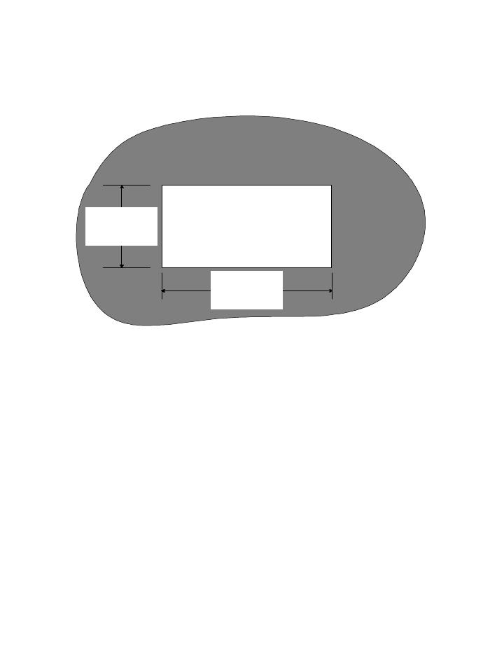
Panel Installation
1. Prepare a mounting panel cutout by cutting a rectangular
hole (3.62” +0.02/-0.0” X 1.77” + 0.02/-0.0”) in the
desired location (see Figure following page). The
maximum panel thickness is 3/8 inches.
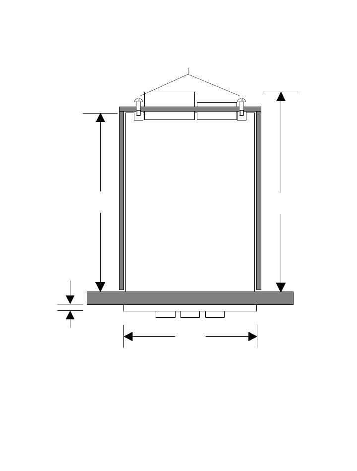
2. Remove the mounting bracket from the instrument
housing by removing the two screws on the rear of the
indicator.
3. Remove the pluggable terminal block located at the rear of
the unit and wire the input power and RS232 or RS485
wires. If an option board is installed in the indicator,
remove
the connector and make the appropriate connections (refer
to
diagram on page 6).
WARNING!
Dangerous voltages are exposed at the screw
terminals. Always remove power before working in
this area for rewiring, disassembly, and all other
activities that involve proximity to electrical
circuitry. Allow at least 10 minutes prior to
working on the unit.
4
4. Install the indicator in the panel cutout from the
front side of the panel. Be sure the instrument is
right-side-up. See figure on following page.
5. Reinstall the mounting bracket on the indicator.
Tighten the bracket screws to achieve a snug fit
against the panel. Avoid distorting or cracking the
housing by not over- tightening the bracket screws.
1.77 in.
+0.02/-0.0
3.62 in.
+0.02/-0.0
PANEL CUTOUT
5
CASE
BRACKET
SCREWS
INSIDE
4.92"
(142mm)
.27"
(7mm)
3.78"
(96mm)
5.80"
(148mm)

6
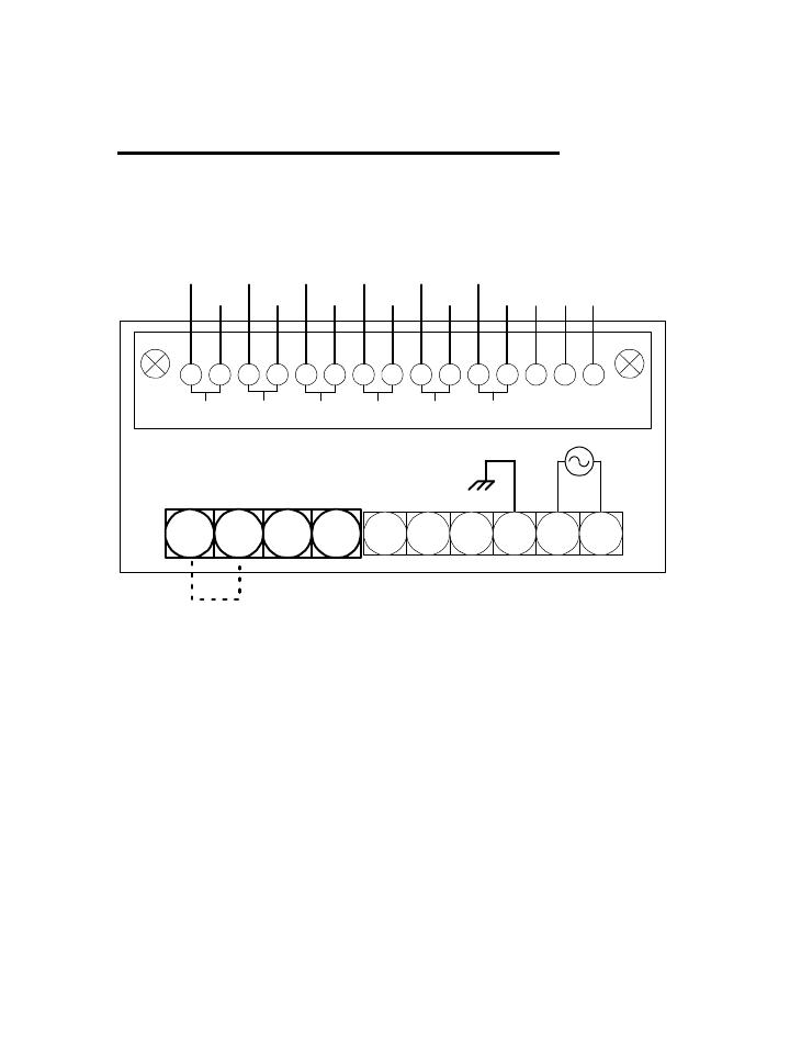
Single Channel Wiring (DP470)
For easy installation, remove the pluggable terminal block
located at the rear of the unit. Connect the input power and
RS232 or RS485 wires to the wire entry locations beneath and
perpendicular to the plug-in direction according to figure
below.
WARNING!
Dangerous voltages are exposed at the screw
terminals. Always remove power before working in
this area for rewiring, disassembly, and all other
activities that involve proximity to electrical
circuitry.
1
2 3 4
5 6 7 8 9 10
-V
+V
SERIAL RXD
SERIAL TXD
SERIAL COM
GND
NEUTRAL
100/240VAC HOT
-I
+I
NOTE: FOR 4 TO 20 mA CURRENT INPUT ADD
JUMPER (NOT INCLUDED) BETWEEN TERMINALS 1
AND 2
7
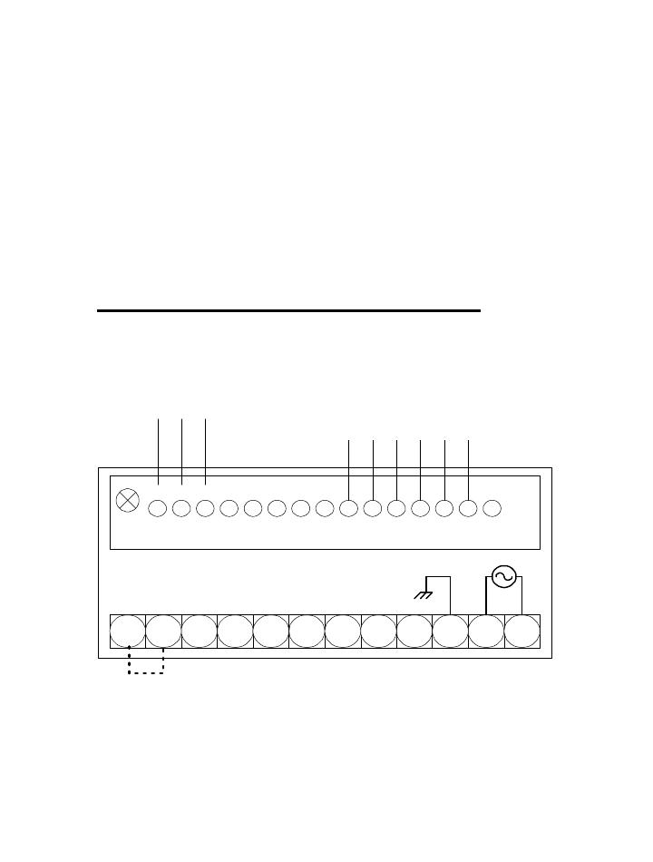
Multiple Channel Wiring (DP472)
Multiple input current configuration:
Remove power and snap off the front panel lens. Leave the
keypad attached to the display board, as it will be required to
enter the calibration menu. Remove the rear pluggable
connectors from the rear of the indicator and slide the main
board electronics out of the case from the front. (Gently lift
the display board above the catch located on the bottom of the
inside of the plastic housing while pushing on the rear male
5 6 7 8 9 10
9
10 11 12 13 14 15
1 2 4 5 6 7 83
CH1 CH2 CH3 CH4 CH5 CH6
RELAY NO
RELAY NC
COMMON
1 2 3 4
+
-
6-CHANNEL MULTIPLE INPUT WIRING DIAGRAM
+
-
+
-
+ +
- -
+
-
NOTE: FOR 4 TO 20 mA CURRENT INPUT ADD
JUMPER (NOT INCLUDED) BETWEEN TERMINALS
1 AND 2
8
connector on the rear of the main board assembly.) Locate the
three-pin header near the rear of the unit. Move the jumper
from position A to position B. Carefully re-install the
electronics back into the housing and wire the inputs
according to the diagram on page 7.
Note: If the multiple input option is used to switch 4
to 20 mA inputs, note that loop continuity will not
be maintained when changing channels.
Analog Output/Dual Alarm Wiring
9 10 11 12 13 14 151 2 4 5 6 7 83
RELAY1 NC
RELAY1 NO
COM1
RELAY2 NC
RELAY2 NO
COM2
1 2 3 4 5 6 7 8 9 10 11 12
ALOG +V/-I
ALOG -V
ALOG +I
NOTE: FOR 4 TO 20 mA CURRENT INPUT ADD JUMPER (NOT
INCLUDED) BETWEEN TERMINALS 1 AND 2

9
Chapter 3
Operation
Your indicator is programmed by a series of menu driven
displays that are operated by three front panel pushbuttons;
Program-PGM, Arrow-∆, and Enter-ENT.
Addressing the main menu items configures the indicator.
The indicator has a program lockout jumper located behind
the front panel lens. Removing the jumper will prevent any
front panel changes of the indicator programming. The
indicator may still be programmed via the computer interface.
Note: When using the DP470 Viewer Software, the front
panel keyboard is automatically disabled.
The basic unit has three main menu items-
1. SCAL: Sets up desired display counts
including decimal points.
2. MATH: Selection enables viewing of either
minimum or maximum value.
3. CAL: Used for calibrating the voltage or
current limits.
PGM
ENT
PROGRAM ARROW ENTER

10
The following menu items are displayed only when the
appropriate option is installed-
4. ALM1/ALM2: Sets relay trip points to
programmed values, hysteresis and delay.
5. AOUT: Programs the indicator to translate the
display to a proportional analog voltage or
current output.
6. MULT: Configures indicator for multiple
voltage or current inputs
Pressing the PGM key allows you to access any of the menus
listed above by placing the indicator in program mode,
indicated by a ‘P’ lit to the right of the display. Placing the
indicator in PGM mode will prevent the indicator from
performing measurements. Any alarm monitoring will be
disabled.
If the PGM key is pressed anywhere within a menu,
the menu reverts to the previous menu level. Repeatedly
pressing the PGM key will return the indicator to the display
mode. Choices within a menu are viewed by pressing the
ARROW key. A menu item is selected by pressing the ENT
key for selection, or edited by pressing the ARROW key.
Generally, the ARROW key allows you to scroll horizontally
through a selection of choices while the ENT key enables you
to make selections and move down vertically to the next menu
item.

11
Unlatching the Relays
The keypad may be used to unlatch the relays in MAN
(manual) mode. If the DP470 Viewer Software is being used
the front panel keypad becomes disabled and the relays can be
unlatched only through the software control panel.
-Relay #1 may be unlatched by pressing and holding
the ARROW key while pressing the PGM key.
-Relay #2 may be unlatched by pressing and holding
the ARROW key while pressing the ENT key.
Scaling and Calibration
For the indicator to display in your desired engineering units,
the indicator must be scaled and then calibrated. Scaling and
calibration are performed in the SCAL and CAL menus
respectively. The SCAL menu allows you to set the desired
engineering units within a range of –999 to +9999 counts.
The CAL menu requires the actual simulation of two
different inputs (typically 0 to 10 Vdc or 4 to 20 mA).
Calibration can be performed through the front panel keypad
or PC interface.
Note: It is not necessary to recalibrate when the
indicator is rescaled.

12
Scaling Procedure
Example: Program the indicator to display 0-5000
lbs. With a 4 to 20mA input signal.
STEP 1. Press the PGM button. PGM will appear on the
display. The indicator status LED will change from L (linear)
to P (for ‘Program Mode’) and the SCAL menu will appear.
Press ENT.
STEP 2. A LOW or HIGH will appear. Pressing the
ARROW key repeatedly will cause LOW and HIGH to
alternate on the display. With LOW on the display, select
LOW by pressing the ENT key. The digits 0000 will appear
with the left most digit flashing. With the ARROW key
select the number 0. Press ENT. The second digit will flash.
Enter 0 again with the ARROW key. Continue on until 0000
is on the display. Press ENT.
STEP 3. A HIGH will appear on the display. Press the
ARROW key. A number with the left most digit flashing will
appear on the display. Using the ARROW key, set the left
most digit until the number 5 appears. Press ENT. The next
digit will flash. Use the ARROW key to set the remaining
digits to 000. With the right most 0 flashing, press ENT.
dCPT will appear.

13
STEP 4. With dCPT on the display, press the ARROW
until the decimal point disappears. Press ENT. The CAL
menu appears on the display. The scaling portion is now
complete.
Calibration Procedure
4 to 20mA Input
STEP 1. Hook up the current input to terminals 1 (-I) and 4
(+I) according the wiring diagram on page 6. In addition, for
4-20mA current inputs install jumper wire between terminals
1 and 2.
STEP 2. With the CAL menu on the display, press ENT.
INLO will appear on the display. Input 4.00 mA and press
ENT. INHI will appear on the display.
STEP 3. With INHI on the display, input 20.0mA into the
meter. Press ENT. Calibration is complete.
0 to 10 Vdc Input
STEP 1. Hook up the current input to terminals 2 (-V) and
3 (+V) according the wiring diagram on page 6.
STEP 2. With the CAL menu on the display, press ENT.
INLO will appear on the display. Input 0.0 Vdc and press
ENT. INHI will appear on the display.
STEP 3. With INHI on the display, input 10.0 Vdc into the
meter. Press ENT. Calibration is complete.

14
Math Function Setup
*For DP472 multi-channel models, MATH
functions can only be viewed through the Omega
DP470 Software.
Example: View the maximum display value recorded.
Note: A running record is kept of the minimum and
maximum display values. Nothing is required to
initiate this recording. These values are there
whenever you need them. You can display the
Minimum or Maximum value by following the steps
below.
STEP 1. With the MATH menu on the display, open this
menu item by pressing the ENT key. MIN will appear on the
display.
STEP 2. Press the Arrow key to toggle between MIN and
MAX. When the display shows MAX, press the ENT key and
the display will now indicate the maximum value. The
MIN/MAX memory may be reset at this point by pressing the
ARROW key. With CLR (CLEAR) on the display, press
ENT. This will restart the recording process. To go back to
the current temperature display, press the PGM button and
the display will indicate the current temperature reading.

15
Multiple Input (DP472)
Note: For multiple-channel 4 to 20 mA current inputs,
see the instructions in Chapter 2 page 7.
The multiple input option will enable the user to
monitor up to 6 same type inputs, either voltage or current.
Any number of channels can be selected manually or scanned
automatically. Alarm limits may be assigned to individual
channels. One NO/NC 5 amp 115VAC relay contact is
available for high or low alarm limit programming.
Two scanning modes are selectable for the multiple
input option- manual (MAN), and automatic (AUTO). MAN
mode allows the user to view a selected channel. Pressing the
arrow key advances the display to the next active channel.
The channel number is indicated by a .4” green LED located
in the upper left-hand corner of the display. To begin
automatic scanning, enter the MULT menu, and select
AUTO. The scan rate is selectable in one-second increments
between 5 and 20 seconds. The display readout will then
sequentially show the display values of the active channels.
Any number of channels may be selected for scanning.
If an alarm limit is exceeded on any displayed
channel, the display will flash, and the relay contact will
latch. The relay will remain latched until the alarm condition
clears. In scanning mode the display will flash on the alarm
channel as it scans.
By using the Omega DP470 Viewer, the DP470 can
log and send multiple channel data through the serial port
making it a miniature datalogger (see Chapter 5).

16
Dual Alarm (DP471,DP473,DP474)
The alarm card has two 5 amp/115VAC relays for high, low
or deviation set points. The alarm card is available by itself or
with analog output (either voltage or current). Relay set
points are programmed through the front panel menu or via
the serial port. An alarm limit may be disabled within the
alarm menu by selecting OFF at the first menu prompt. If
OFF is selected the display will return to the next main menu
item for further programming. If ON is selected the menu
proceeds down through the alarm menu for further set point
programming.
The relays can be operated in MAN or AUTO mode.
In AUTO mode, the relay unlatches by itself once the alarm
limit is no longer exceeded.
In MAN mode the relay is reset manually. However,
the display continues to flash until the alarm limit is no
longer exceeded.
- Pressing and holding the ARROW key and pressing
the PGM key resets Relay 1 (ALM1).
- Pressing and holding the ARROW key and pressing
the ENT key resets Relay 2 (ALM2)
Note: When using Viewer Software, the front panel keys
are disabled. Relays must therefore be reset using the
Unlatch buttons on the Viewer control panel.
When HIGH is selected, a displayed value greater
than the limit value will cause an alarm. When LOW is
selected, a displayed value less than the limit value will cause
an alarm.
17
Note: When setting alarm limits enter only the raw
counts. Ignore any decimal points. For example, an
alarm limit of 100.0 would be entered as 1000.
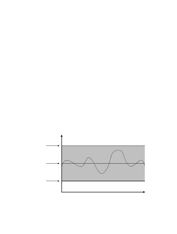
Using Deviation
Deviation allows the user to assign alarm limits above and
below the normal operating points of a process. If the
displayed value remains within the high and low deviation set
points no alarm occurs. If the displayed value equals or
exceeds either the high or low deviation limits an alarm
occurs. Hysteresis and delay are also programmable for
deviation set points (see following explanations). Deviation
allows the user to assign two set points per alarm relay for a
total of four alarm set points per alarm option (See drawing
below). This could be useful for indicating a warning
condition with one relay and an emergency condition for the
other relay.
TIME
upper
deviation
limit
lower
deviation
limit
normal
operating
point

18
Hysteresis
Hysteresis or deadband is used to prevent the latching and
unlatching of an alarm relay around the set point. Hysteresis
is selectable from 0-500 counts in 1-count increments.
Hysteresis assumes negative values for HIGH limits and
positive values for LOW limits.
For example:
- Alarm limit set to High
- The alarm set point is 5000
- Hysteresis is set at 50 counts
If the display value exceeds 5000, the alarm relay closes and
the display flashes. The relay will not open until the display
value drops below 4950.
Delay
Programming the meter for alarm delay prevents an alarm
trip for a specified period of time (0-99 seconds). An alarm
delay would be used whenever an unstable or noisy input
signal is present. By filtering out short duration alarm
conditions, alarm delay prevents unnecessary alarms from
occurring.
Analog Output (DP473, DP474)
The analog output option translates the indicators’ display
reading to a proportional analog output signal. There are two
versions of the analog output option, either 0-10VDC
(DP473) or 4 to 20ma (DP474). Both voltage and current
outputs are scalable within their ranges and are similarly
programmed. Note that the analog output is active only in the
display mode. When in Program mode, the output goes to its

19
zero output value. The display reading can be scaled from -
999 to +9999, which enables the user to use only a portion of
the full scale if necessary.
Analog Output Setup
Example 1: Program the indicator to output 4.0 ma at 0
lbs. and 20.0 ma at 8000lbs.
STEP 1. Press the PGM button. PGM will appear on the
display. The P/L LED will change from L to P (for ‘Program
Mode’).
STEP 2. Press the Arrow key until ALOG appears on the
display. Open the ALOG Menu for programming by pressing
the ENT key.
STEP 3. A LOW or HIGH will appear. Pressing the Arrow
key repeatedly will cause LOW and HIGH to alternate on the
display. With LOW on the display, select LOW by pressing
the ENT key. The digits 0000 will appear with the left most
digit flashing. With the ARROW key select the number 0.
Press ENT. The second digit will flash. Enter 0 again with
the ARROW key. Continue on until 0000 is on the display
with the right most digit flashing. Press ENT.
STEP 4. HIGH will appear on the display. Press ENT. Set
the first digit to 8 by using the ARROW button. Set the
second digit to 0 and so on until 8000 is on the display. With
the farthest digit to the right flashing, press ENT. The next
menu item appears.
/