
SOLID-STATE MEMORY CAMCORDER
PMW-500
OPERATION MANUAL [English]
1st Edition (Revised 2)
4260128030
The supplied CD-ROM includes operation manuals for the PMW-500 Solid-State
Memory Camcorder (English, Japanese, French, German, Italian, Spanish and Chinese
versions) in PDF format.
For more details, see “Using the CD-ROM” on page 14.
PMW-500
(SYM)
4-260-128-03 (1)
Sony Corporation
Printed on recycled paper.
Printed in Japan
2011.03 32
© 2010
SOLID-STATE MEMORY CAMCORDER PMW-500

2
To reduce the risk of fire or
electric shock, do not
expose this apparatus to
rain or moisture.
To avoid electrical shock,
do not open the cabinet.
Refer servicing to qualified
personnel only.
Important Safety Instructions
• Read these instructions.
• Keep these instructions.
• Heed all warnings.
• Follow all instructions.
• Do not use this apparatus near water.
• Clean only with dry cloth.
• Do not block any ventilation openings.
Install in accordance with the
manufacturer’s instructions.
• Do not install near any heat sources such
as radiators, heat registers, stoves, or
other apparatus (including amplifiers) that
produce heat.
• Do not defeat the safety purpose of the
polarized or grounding-type plug. A
polarized plug has two blades with one
wider than the other. A grounding-type
plug has two blades and a third grounding
prong. The wide blade or the third prong
are provided for your safety. If the
provided plug does not fit into your outlet,
consult an electrician for replacement of
the obsolete outlet.
• Protect the power cord from being walked
on or pinched particularly at plugs,
convenience receptacles, and the point
where they exit from the apparatus.
• Only use attachments/accessories
specified by the manufacturer.
• Refer all servicing to qualified service
personnel. Servicing is required when the
apparatus has been damaged in any way,
such as power-supply cord or plug is
damaged, liquid has been spilled or
objects have fallen into the apparatus, the
apparatus has been exposed to rain or
moisture, does not operate normally, or
has been dropped.
WARNING
Excessive sound pressure from earphones
and headphones can cause hearing loss.
In order to use this product safely, avoid
prolonged listening at excessive sound
pressure levels.
For the customers in the U.S.A.
This equipment has been tested and found
to comply with the limits for a Class B digital
device, pursuant to Part 15 of the FCC
Rules. These limits are designed to provide
reasonable protection against harmful
interference in a residential installation. This
equipment generates, uses, and can radiate
radio frequency energy and, if not installed
and used in accordance with the
instructions, may cause harmful interference
to radio communications. However, there is
no guarantee that interference will not occur
in a particular installation. If this equipment
does cause harmful interference to radio or
television reception, which can be
determined by turning the equipment off and
on, the user is encouraged to try to correct
the interference by one or more of the
following measures:
- Reorient or relocate the receiving
antenna.
- Increase the separation between the
equipment and receiver.
- Connect the equipment into an outlet on a
circuit different from that to which the
receiver is connected.
- Consult the dealer or an experienced
radio/TV technician for help.
You are cautioned that any changes or
modifications not expressly approved in this
manual could void your authority to operate
this equipment.
All interface cables used to connect
peripherals must be shielded in order to
comply with the limits for a digital device
pursuant to Subpart B of Part 15 of FCC
Rules.
If you have any questions about this product,
you may call;
WARNING

3
Sony Customer Information Service Center
1-800-222-7669 or http://www.sony.com/
For the customers in Canada
This Class B digital apparatus complies with
Canadian ICES-003.
For the customers in Europe
This product with the CE marking complies
with the EMC Directive issued by the
Commission of the European Community.
Compliance with this directive implies
conformity to the following European
standards:
• EN55103-1: Electromagnetic
Interference(Emission)
• EN55103-2: Electromagnetic
Susceptibility(Immunity)
This product is intended for use in the
following Electromagnetic Environments: E1
(residential), E2 (commercial and light
industrial), E3 (urban outdoors), E4
(controlled EMC environment, ex. TV
studio).
The manufacturer of this product is Sony
Corporation, 1-7-1 Konan, Minato-ku,
Tokyo, Japan.
The Authorized Representative for EMC and
product safety is Sony Deutschland GmbH,
Hedelfinger Strasse 61, 70327 Stuttgart,
Germany.
For the State of California, USA only
Perchlorate Material - special handling may
apply, See
www.dtsc.ca.gov/hazardouswaste/
perchlorate
Perchlorate Material : Lithium battery
contains perchlorate.
For the customers in Taiwan only
Afin de réduire les risques
d’incendie ou
d’électrocution, ne pas
exposer cet appareil à la
pluie ou à l’humidité.
Afin d’écarter tout risque
d’électrocution, garder le
coffret fermé. Ne confier
l’entretien de l’appareil
qu’à un personnel qualifié.
AVERTISSEMENT
Une pression acoustique excessive en
provenance des écouteurs ou du casque
peut provoquer une baisse de l’acuité
auditive.
Pour utiliser ce produit en toute sécurité,
évitez l’écoute prolongée à des pressions
sonores excessi
Pour les clients au Canada
Cet appareil numérique de la classe B est
conforme à la norme NMB-003 du Canada.
Pour les clients en Europe
Ce produit portant la marque CE est
conforme à la Directive sur la compatibilité
électromagnétique (EMC) émise par la
Commission de la Communauté
européenne.
Declaration of Conformity
Trade Name : SONY
Model : PMW-500
Responsible party : Sony Electronics Inc.
Address : 16530 Via Esprillo,
San Diego, CA
92127 U.S.A.
Telephone Number : 858-942-2230
This device complies with part 15 of the
FCC Rules. Operation is subject to the
following two conditions: (1) this device
may not cause harmful interference, and
(2) this device must accept any
interference received, including
interference that may cause undesired
operation.
AVERTISSEMENT

4
La conformité à cette directive implique la
conformité aux normes européennes
suivantes :
• EN55103-1 : Interférences
électromagnétiques (émission)
• EN55103-2 : Sensibilité
électromagnétique (immunité)
Ce produit est prévu pour être utilisé dans
les environnements électromagnétiques
suivants : E1 (résidentiel), E2 (commercial et
industrie légère), E3 (urbain extérieur) et E4
(environnement EMC contrôlé, ex. studio de
télévision).
Le fabricant de ce produit est Sony
Corporation, 1-7-1 Konan, Minato-ku,
Tokyo, Japon.
Le représentant autorisé pour EMC et la
sécurité des produits est Sony Deutschland
GmbH, Hedelfinger Strasse 61, 70327
Stuttgart, Allemagne.
Um die Gefahr von Bränden
oder elektrischen Schlägen
zu verringern, darf dieses
Gerät nicht Regen oder
Feuchtigkeit ausgesetzt
werden.
Um einen elektrischen
Schlag zu vermeiden, darf
das Gehäuse nicht geöffnet
werden. Überlassen Sie
Wartungsarbeiten stets nur
qualifiziertem
Fachpersonal.
WARNUNG
Zu hoher Schalldruck von Ohrhörern und
Kopfhörern kann Gehörschäden
verursachen.
Um dieses Produkt sicher zu verwenden,
vermeiden Sie längeres Hören bei sehr
hohen Schalldruckpegeln.
Für Kunden in Europa
Dieses Produkt besitzt die CE-
Kennzeichnung und erfüllt die EMV-
Richtlinie der EG-Kommission.
Angewandte Normen:
• EN55103-1: Elektromagnetische
Verträglichkeit (Störaussendung)
• EN55103-2: Elektromagnetische
Verträglichkeit (Störfestigkeit)
Für die folgenden elektromagnetischen
Umgebungen: E1 (Wohnbereich), E2
(kommerzieller und in beschränktem Maße
industrieller Bereich), E3 (Stadtbereich im
Freien) und E4 (kontrollierter EMV-Bereich,
z.B. Fernsehstudio).
Der Hersteller dieses Produkts ist Sony
Corporation, 1-7-1 Konan, Minato-ku,
Tokyo, Japan.
Der autorisierte Repräsentant für EMV und
Produktsicherheit ist Sony Deutschland
GmbH, Hedelfinger Strasse 61, 70327
Stuttgart, Deutschland.
WARNUNG

Table of Contents
5
Table of Contents
Foreword .................................................................................................... 11
Before Use....................................................................................... 11
Mode Indications in This Manual ............................................................ 11
Chapter 1 : Overview
Features ...................................................................................................... 12
Using the CD-ROM ................................................................................... 14
Reading the CD-ROM Manuals ............................................................... 14
Locations and Functions of Parts and Controls...................................... 15
Power Supply .................................................................................. 15
Accessory Attachments................................................................... 16
Operating and Connectors Section.................................................. 17
LCD Monitor................................................................................... 26
HDVF-20A Viewfinder (Optional)................................................. 28
CBK-VF01 Viewfinder (Optional) ................................................. 29
Status Display on the Viewfinder Screen........................................ 30
Chapter 2 : Preparations
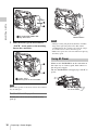
Preparing a Power Supply ........................................................................ 35
Using a Battery Pack....................................................................... 35
Using AC Power ............................................................................. 36
Attaching the Viewfinder.......................................................................... 37
Attaching the Viewfinder................................................................ 37
Adjusting the Viewfinder Position.................................................. 37
Using the BKW-401 Viewfinder Rotation Bracket ........................ 38
Detaching the Eyepiece................................................................... 39
Adjusting the Viewfinder Focus and Screen................................... 39
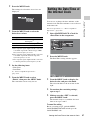
Setting the Area of Use .............................................................................. 40
Setting the Date/Time of the Internal Clock ........................................... 41
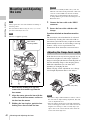
Mounting and Adjusting the Lens............................................................ 42
Adjusting the Flange Focal Length................................................. 42
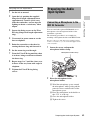
Preparing the Audio Input System .......................................................... 43
Connecting a Microphone to the MIC IN Connector...................... 43
Connecting Microphones to the AUDIO IN Connectors................ 44
Table of Contents

Table of Contents
6
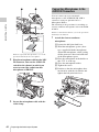
Attaching a UHF Portable Tuner (for a UHF Wireless Microphone
System) ..................................................................................... 45
Connecting Line Input Audio Equipment ....................................... 47
Tripod Mounting ....................................................................................... 48
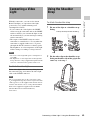
Connecting a Video Light ......................................................................... 49
Using the Shoulder Strap .......................................................................... 49
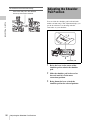
Adjusting the Shoulder Pad Position ....................................................... 50
Chapter 3 : Adjustments and Settings
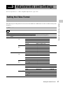
Setting the Video Format .......................................................................... 51
Selecting the Recording Mode........................................................ 53
Changing the Video Format ............................................................ 53
Adjusting the Black Balance and the White Balance ............................. 54
Adjusting the Black Balance........................................................... 54
Adjusting the White Balance .......................................................... 55
Setting the Electronic Shutter................................................................... 57
Shutter Modes ................................................................................. 57
Selecting the Shutter Mode and Shutter Speed ............................... 57
Changing the Reference Value for Automatic Iris Adjustment ............ 59
Adjusting the Audio Level ........................................................................ 60
Manually Adjusting the Audio Levels of the Audio Inputs from the
AUDIO IN CH-1/CH-2 Connectors ......................................... 60
Manually Adjusting the Audio Level of the MIC IN Connector .... 60
Recording Audio on Channels 3 and 4 ........................................... 61
Setting the Time Data................................................................................ 62
Setting the Timecode....................................................................... 62
Setting the User Bits........................................................................ 63
Synchronizing the Timecode........................................................... 63
Setting Shot Data ....................................................................................... 65
Creating a Shot ID........................................................................... 65
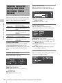
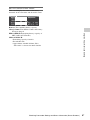
Checking Camcorder Settings and Status Information
(Status Screens).................................................................................... 66
Chapter 4 : Shooting
Handling SxS Memory Cards................................................................... 68
About SxS Memory Cards .............................................................. 68
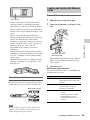
Loading and Ejecting SxS Memory Cards...................................... 69
Selecting the SxS Memory Card to Use.......................................... 70

Table of Contents
7
Formatting (Initializing) SxS Memory Cards ................................. 70
If You Load a Memory Card Formatted in the Different Recording
Mode from the Mode Selected on the Camcorder.................... 71
Checking the Remaining Recording Time...................................... 71
Restoring SxS Memory Cards......................................................... 72
Handling USB Flash Drives ...................................................................... 73
Formatting (Initializing) USB Flash Drives.................................... 73
Restoring USB Flash Drives ........................................................... 74
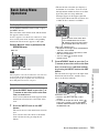
Basic Operations ........................................................................................ 74
Playing Recorded Clips................................................................... 76
Deleting Recorded Clips ................................................................. 77
Advanced Operations ................................................................................ 77
Recording Shot Marks..................................................................... 77
Setting OK Marks ........................................................................... 78
Starting to Record from Pre-stored Video
(Picture Cache Function) .......................................................... 78
Recording Time-lapse Video (Interval Rec Function).................... 79
Shooting Stop Motion Animations (Frame Rec Function) ............. 81
Shooting with Slow & Quick Motion ............................................. 82
Recording with the Clip Continuous Rec Function ........................ 83
Framing Shots with the Freeze Mix Function................................. 84
Recording Proxy Data ............................................................................... 85
Recording Proxy Data While Recording Clips ............................... 85
Recording Proxy Data for Existing Clips........................................ 86
Deleting All Proxy Data from a USB Flash Drive.......................... 86
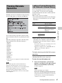
Planning Metadata Operations ................................................................ 87
Loading a Planning Metadata File into Camcorder’s Internal
Memory..................................................................................... 87
Defining Clip Names in Planning Metadata ................................... 88
Defining Shot Mark Names in Planning Metadata ......................... 90
Chapter 5 : Clip Operations
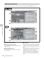
Clip Playback ............................................................................................. 91
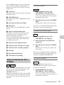
Thumbnail Screen ........................................................................... 91
Playing Clips ................................................................................... 94
Using Thumbnails to Search Inside Clips....................................... 95
Thumbnail Operations .............................................................................. 96
THUMBNAIL Menu Configuration ............................................... 96
Basic THUMBNAIL Menu Operations.......................................... 98
Changing the Thumbnail Screen Type............................................ 98
Displaying Clip Properties ............................................................ 100
Adding and Deleting OK, NG or KP Marks................................. 101

Table of Contents
8
Protecting Clips............................................................................. 102
Copying Clips ............................................................................... 102
Deleting Clips................................................................................ 103
Displaying the Expand Thumbnail Screen.................................... 104
Displaying the Essence Mark Thumbnail Screen ......................... 105
Adding and Deleting Shot Marks.................................................. 106
Changing Clip Index Pictures ....................................................... 106
Dividing Clips ............................................................................... 106
Chapter 6 : Menu and Detailed Settings
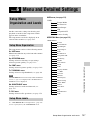
Setup Menu Organization and Levels.................................................... 107
Setup Menu Organization ............................................................. 107
Setup Menu Levels........................................................................ 107
Basic Setup Menu Operations ................................................................ 109
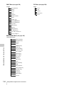
Menu List.................................................................................................. 111
USER Menu (Factory Default Configuration).............................. 111
OPERATION Menu...................................................................... 112
PAINT Menu................................................................................. 129
MAINTENANCE Menu ............................................................... 135
FILE Menu.................................................................................... 150
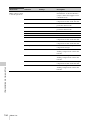
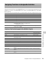
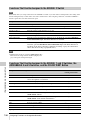
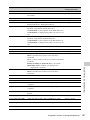
Assigning Functions to Assignable Switches ......................................... 155
Functions That Can Be Assigned to the ASSIGN. 0 Switch ........ 155
Functions That Can Be Assigned to the ASSIGN. 2 Switch ........ 156
Functions That Can Be Assigned to the ASSIGN. 1 and 3 Switches,
the ASSIGNABLE 4 and 5 Switches, and the COLOR TEMP.
Button...................................................................................... 156
Functions That Can Be Assigned to the RET Button on the Lens 159
Chapter 7 : Saving and Loading User Setting Data
Saving and Loading Settings................................................................... 160
Saving Setting Data....................................................................... 160
Loading Setting Data..................................................................... 161
Resetting a File after Changing Its Contents................................. 162
Saving and Loading Scene Files ............................................................. 162
Saving Scene Files ........................................................................ 162
Loading Scene Files ...................................................................... 163
Saving and Loading Lens Files............................................................... 164
Setting Lens File Data................................................................... 164
Saving Lens Files .......................................................................... 164
Loading Lens Files........................................................................ 164

Table of Contents
9
Loading Lens Files Automatically................................................ 165
Saving and Loading User Files ............................................................... 165
Saving User Files .......................................................................... 165
Loading Setting Data..................................................................... 166
Chapter 8 : Connecting External Devices
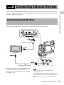
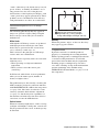
Connecting External Monitors ............................................................... 167
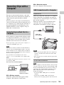
Operating Clips with a Computer.......................................................... 169
Using the ExpressCard Slot of a Computer .................................. 169
USB Connection with a Computer................................................ 169
Connecting an External Device (i.LINK Connection).......................... 171
Recording the Camera Picture on an External Device.................. 171
Nonlinear Editing.......................................................................... 172
Recording External Input Signals ................................................. 172
Configuring a Shooting and Recording System .................................... 173
Chapter 9 : Maintenance
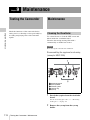
Testing the Camcorder............................................................................ 174
Maintenance ............................................................................................. 174
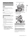
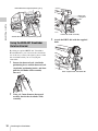
Cleaning the Viewfinder ............................................................... 174
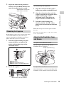
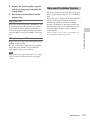
Note about the Battery Terminal................................................... 175
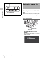
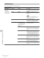
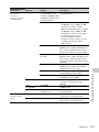
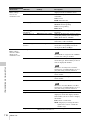
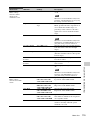
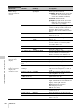
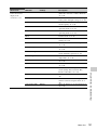
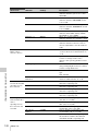
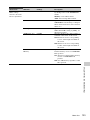
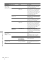
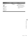
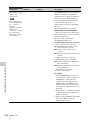
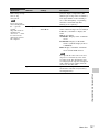
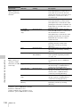
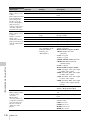
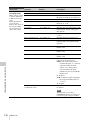
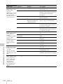
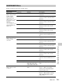
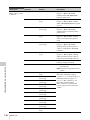
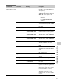
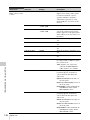
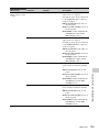
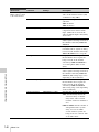
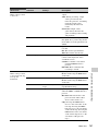
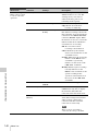
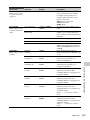
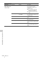
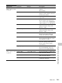
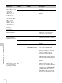
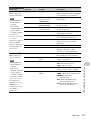
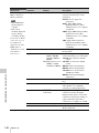
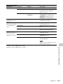
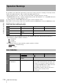
Operation Warnings................................................................................ 176
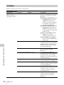
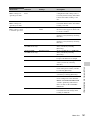
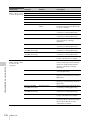
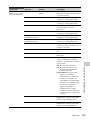
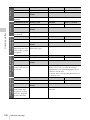
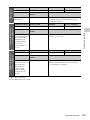
Error Indication............................................................................. 176
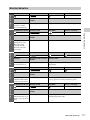
Warning Indication........................................................................ 177
Appendix
Important Notes on Operation ............................................................... 184
Exchanging the Battery of the Internal Clock ...................................... 186
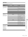
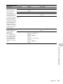
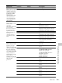
Specifications............................................................................................ 186
General .......................................................................................... 186
Camera Block................................................................................ 187
Audio Block .................................................................................. 188
Display .......................................................................................... 188
Media Block .................................................................................. 188
Inputs/Outputs ............................................................................... 188
Supplied Accessories .................................................................... 189
Recommended Additional Equipment .......................................... 189

Table of Contents
10
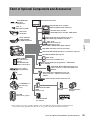
Chart of Optional Components and Accessories .................................. 191
About i.LINK ........................................................................................... 192
MPEG-4 Visual Patent Portfolio License .............................................. 193
MPEG-2 Video Patent Portfolio License ............................................... 193
About Bitmap Fonts ................................................................................ 193
About OpenSSL ....................................................................................... 194
Index.......................................................................................................... 197

Foreword / Mode Indications in This Manual
11
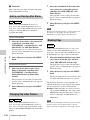
After purchasing the PMW-500 Solid-State
Memory Camcorder, before operating, it is
necessary to set the area of use.
(Unless this setting is made, the camcorder will
not operate.)
For details of these settings, see “Setting the Area of
Use” (page 40).
Note
Before attaching/removing optional components or
accessories to/from the PMW-500 (referred to as “the
camcorder”), be sure to turn the power of the camcorder
off.
Some functions and information are available
only when this camcorder is in a specific
operating mode. This manual indicates those
modes by using the following marks. When these
marks appear, the associated function or
information is available only in that mode.
HD mode: When OPERATION >Format >HD/
SD in the setup menu is set to [HD].
UDF mode: When OPERATION >Format >File
System in the setup menu is set to [UDF].
FAT mode: When OPERATION >Format >File
System in the setup menu is set to [FAT].
FAT-HD mode: When OPERATION >Format
>File System in the setup menu is set to [FAT]
and OPERATION >Format >HD/SD in the setup
menu is set to [HD].
FAT-SD mode: When OPERATION >Format
>File System in the setup menu is set to [FAT]
and OPERATION >Format >HD/SD in the setup
menu is set to [SD].
Foreword
Before Use
Mode Indications in This
Manual
HD
UDF
FAT
FAT-HD
FAT-SD

Features
12
Chapter 1 Overview
2
/
3
-inch full-HD “PowerHAD FX” CCDs
• IT (Interline Transfer)
2
/
3
-inch progressive
image sensors with 207 million pixels, for full
HD resolution (1920 × 1080)
• “PowerHAD FX” CCDs, featuring a signal
processing ASIC with 14-bit A/D converters
These new image sensor technologies enable
the capture of very high-quality images, with
F11 (59.94i) and F12 (50i) sensitivity and an
SN ratio of 59 dB.
1)
1) With noise suppression on (off value is 54 dB) Noise
suppression uses proprietary Sony signal processing
technology to suppress noise in highfrequency
regions.
SxS memory cards as recording media
Using SxS memory cards, the camcorder offers
nonlinear capabilities such as instant random
access and file-based operation.
You can choose FAT or UDF as the file system
for recording media.
Light weight, low power consumption
Design features custom video signal processing
ICs, and SxS memory card recording enable
fanless operation and power consumption of 27
W or less. The camcorder’s light weight (3.4 kg
(7 lb 7.9 oz)) and low center of gravity make it
easy to carry on the shoulder while ensuring
superior stability.
HD recording using the “MPEG-2 Long
GOP” codec and SD recording in MPEG
IMX50/DVCAM format
The camcorder records 1920 × 1080, 1440 ×
1080, and 1280 × 720 HD images using “MPEG-
2 Long GOP” codec compression.
For recording in FAT mode, it offers a choice of
bit rates: either 35 Mbps (HQ mode) or 25 Mbps
(SP mode).
For recording in UDF mode, it offers a choice of
bit rates: either 35 Mbps (HQ mode) or 50 Mbps
(HD422 mode).
By utilizing an efficient compression format, the
camcorder records high-quality HD images for
long recording time of approx. 60 minutes at 50
Mbps (HD422 mode) or approx. 90 minutes at 35
Mbps (HQ mode) on a single 32-GB SxS memory
card (when the recording mode is UDF).
It can also record and play two SD formats:
MPEG IMX 50 Mbps and DVCAM 25 Mbps.
1)
1) CBK-MD01 SD Record and Playback Key required.
For details, contact a Sony service representative
Multi-format support
The camcorder supports interlace format
recording (1080/59.94i or 1080/50i), progressive
format recording (1080/29.97P, 1080/23.98P,
720/59.94P, 720/29.97P, 720/23.98P, or 1080/
25P, 720/50P, 720/25P), thus offering the
flexibility needed for worldwide HD recording.
It also supports recording and playback of SD
signals (both NTSC and PAL). The camcorder
has an optional capability to record and play back
SD signals in IMX/DVCAM format, and can
output HD signals down-converted to SD.
A variety of functions for improved
performance under various shooting
conditions
• Picture Cache function
• Optical ND filters and electrical CC filters
• Hyper gamma
• Slow shutter function
• Clip Continuous Rec function
• Frame Recording function
• Time lapse function (interval recording)
• Slow & quick motion function
• Freeze mix function
• Live & Play function
• Digital extender function
1)
• Focus magnification function
• Assignable switches
Chapter1 Overview
Features

Features
13
Chapter 1 Overview
• 3.5-inch high-resolution color LCD monitor
• Remote control
1) When the optional CBK-HD02 SDI/Composite Input
and 50-pin Interface is installed
Recording data to USB flash drives and
reading data from USB flash drives (UDF
mode)
You can connect USB flash drives to the external
device connector to record proxy data or read
planning metadata. You can also save setup menu
settings to USB flash drives and load menu
settings from USB flash drives into the
camcorder.
Wireless LAN support
You can connect this camcorder to a computer
over a wireless LAN (Wi-Fi connection) by
installing the optional CBK-UPG01 Hardware
Upgrade Key and connecting the optional CBK-
WA01 Wi-Fi Adapter to the external device
connector.
A Wi-Fi connection allows you to transfer
planning metadata from a computer to this
camcorder, and to transfer clips and other files
from this camcorder to a computer. You can also
use the Live Logging function to transfer proxy
AV data to a computer as you shoot, for logging
of the video currently being shot.
Inherits unique features of XDCAM series
The camcorder inherits the workflow features of
the XDCAM series, including thumbnail display
and metadata management, and improves them
by introducing an improved man-machine
interface.
Supports two viewfinder types
Depending on the application, you can use either
the optional HDVF series viewfinder or the CBK-
VF01 color viewfinder.
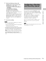
Camcorder system configuration
When you install the optional CBK-HD02 SDI/
Composite Input and 50-pin Interface, you can
mount the XDCA-55 HD Camera Adaptor and
connect the XDCU-50 HD Camera Extension
Unit to configure a system for shooting and
recording.
When the CBK-HD02 is installed, you can also
connect the HDCA-702 MPEG TS Adaptor
instead of the camera adaptor. This allows you to
convert this camcorder’s HDSDI output to a
MPEG HD transport stream.

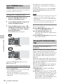
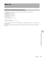
Using the CD-ROM / Reading the CD-ROM Manuals
14
Chapter 1 Overview
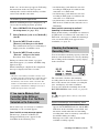
Two CD-ROMs are supplied with the camcorder.
The CD-ROM labeled “Manuals for Solid-State
Memory Camcorder” contains the PDF files of
OPERATION MANUAL and SUPPLEMENT
for the camcorder (English, Japanese, French,
German, Italian, Spanish and Chinese).
The CD-ROM labeled “Utility Software for
XDCAM” contains application and device driver
software required to access to SxS memory cards
from a computer and to manage material shot
with the camcorder.
Information about how to install the software is
provided in PDF format.
Note
You must install the SxS device driver and SxS UDF
driver software on your computer if it is equipped with
an ExpressCard slot and you want to use it to access SxS
memory cards, if you want to connect the camcorder to
your computer, and if you want to connect an optional
SBAC-US10 SxS Memory Card USB Reader/Writer to
the computer.
Preparations
The following program must be installed on your
computer in order to read the documents
contained on the CD-ROM.
Adobe Reader Version 6.0 or higher
Memo
If Adobe Reader is not installed, you can download it
from the following URL:
http://www.adobe.com/
Adobe and Adobe Reader are trademarks of Adobe
Systems Incorporated in the United States and/or other
countries.
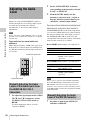
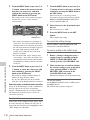
To read the documents
Do the following:
1 Insert the CD-ROM in your CD-ROM
drive.
A cover page appears automatically in your
browser.
If it does not appear automatically in the
browser, double-click on the index.htm file
on the CD-ROM.
2 Select and click on the manual that you
wish to read.
This opens the PDF file.
Memo
The files may not be displayed properly, depending on
the version of Adobe Reader. In such a case, install the
latest version you can download from the URL
mentioned in “Preparations” above.
Note
If you have lost or damaged the CD-ROM, you can
purchase a new one to replace it. Contact a Sony service
representative.
Using the CD-ROM Reading the CD-ROM
Manuals

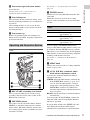
Locations and Functions of Parts and Controls
15
Chapter 1 Overview
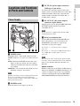
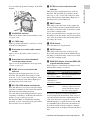
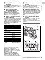
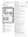
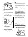
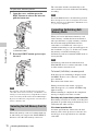
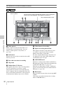
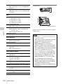
a LIGHT switch
Determines how a video light connected to the
LIGHT connector (see page 16) is turned on and
off.
AUTO: When the POWER switch of the video
light is in the on position, the video light is
turned on automatically while the camcorder
is recording.
MANUAL: You can turn the video light on or off
manually, using its own switch.
Note
When the camcorder is set for recording in Picture Cache
mode, it is not possible to turn on the light before
operation to start recording is carried out (or while data
is being stored in memory).
b POWER switch
Turns the main power supply on and off.
c DC IN (DC power input) connector
(XLR type, 4-pin, male)
To operate the camcorder from an AC power
supply, connect an optional DC power cord to this
terminal and then connect the cord to the DC
output terminal of the BC-L70, BC-L160, or
another battery charger.
d DC OUT 12V (DC power output)
connector (4-pin, female)
Supplies power for an optional WRR-860C/861/
862 UHF Synthesized Diversity Tuner
(maximum 0.5 A).
Note
Do not connect any equipment other than the UHF
synthesized diversity tuner.
e Battery attachment shoe
Attach a BP-GL95/GL65/L80S/L60S Battery
Pack. Alternatively, you can attach an AC-
DN2B/DN10 AC Adaptor to operate the
camcorder on AC power supply.
For details, see “Preparing a Power Supply”
(page 35).
For details, see “Attaching a UHF Portable Tuner
(for a UHF Wireless Microphone System)”
(page 45).
Note
For your safety, and to ensure proper operation of the
camcorder, Sony recommends the use of the following
battery packs: BP-GL95, BP-GL65, BP-L60S, and
BP-L80S.
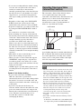
Adaptor connector
Enables connection of an XDCA-55 HD Camera
Adaptor or an HDCA-702 MPEG TS Adaptor. To
connect an adaptor, remove the cover from the
connector and install the optional CBK-HD02
SDI/COMPOSITE Input and 50 Pin Interface.
Locations and Functions
of Parts and Controls
Power Supply
Adaptor connector (see page 15
)

Locations and Functions of Parts and Controls
16
Chapter 1 Overview
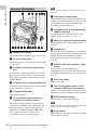
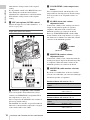
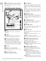
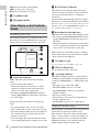
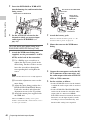
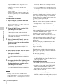
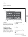
a Shoulder strap fitting
Attach the supplied shoulder strap (see page 49).
b Accessory fitting shoe
Attach an optional accessory such as a video light
(see page 49).
c Viewfinder front-to-back positioning
lever
To adjust the viewfinder position in the front-to-
back direction, loosen this lever and the LOCK
knob. After adjustment, retighten this lever and
the LOCK knob.
d Viewfinder left-to-right positioning ring
Loosen this ring to adjust the left-to-right position
of the viewfinder (see page 37).
e Viewfinder fitting shoe
Attach the viewfinder.
f VF (viewfinder) connectors (26-pin,
rectangular and 20-pin, round)
The analog interface connector (20-pin) is for
connection of an HDVF series viewfinder, and
the digital interface connector (26-pin) is for
connection of an HD viewfinder CBK-VF01.
Use a connection cable to connect your
viewfinder to the corresponding connector.
Note
Do not connect viewfinders to both connectors at the
same time.
g Lens mount securing rubber
After locking the lens in position using the lens
locking lever, fit this rubber over the lower of the
two projections. This fixes the lens mount,
preventing it from coming loose.
h Viewfinder front-to-back positioning
knob (LOCK knob)
Loosen this knob to adjust the front-to-back
position of the viewfinder (see page 37).
i Fitting for optional microphone holder
Fit an optional CAC-12 Microphone Holder (see
page 44).
j Shoulder pad
Raise the shoulder pad fixing lever to adjust the
position in the front-to-rear direction. Adjust the
position for maximum convenience when
operating the camcorder on your shoulder (see
page 50).
k LIGHT (video light) connector (2-pin,
female)
A video light with a maximum power
consumption of 50 W, such as the Anton Bauer
Ultralight 2 or equivalent can be connected (see
page 49).
l Lens cable clamp
Clamp a lens cable.
m MIC IN (microphone input) (+48 V)
connector (XLR type, 5-pin, female)
Connect a stereo microphone to this connector.
The power (+48 V) is supplied via this connector.
n LENS connector (12-pin)
Connect a lens cable to this connector.
Note
When connecting or disconnecting the lens cable to this
connector, power off the camcorder first.
o Tripod mount
When using the camcorder on a tripod, attach the
tripod adaptor (optional).
Accessory Attachments

Locations and Functions of Parts and Controls
17
Chapter 1 Overview
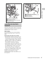
p Lens mount (special bayonet mount)
Attach the lens.
Consult a Sony service representative for
information about available lenses.
q Lens locking lever
After inserting the lens in the lens mount, rotate
the lens mount ring with this lever to lock the lens
in position.
After locking the lens, be sure to use the lens
mount securing rubber to prevent the lens from
becoming detached.
r Lens mount cap
Remove by pushing up the lens locking lever.
When no lens is mounted, keep this cap fitted for
protection from dust.
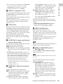
Front
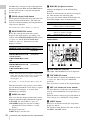
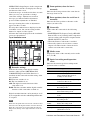
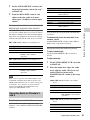
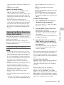
a REC START (recording start) button
Press to start recording. Press it again to stop
recording. The effect is the same as that of the
REC button on the lens.
b SHUTTER selector
Set to ON to use the electronic shutter. Push to
SELECT to switch the shutter speed or shutter
mode setting. When this switch is operated, the
new setting appears on the viewfinder screen for
about three seconds.
For details, see “Setting the Electronic Shutter”
(page 57).
c FILTER selector
Switches between four ND filters built into this
camcorder.
When this selector is used, the new setting
appears on the viewfinder screen for about three
seconds.
You can change a MAINTENANCE menu
setting so that different white balance settings can
be stored for different FILTER selector positions.
This allows you to automatically obtain optimum
white balance for the current shooting conditions
in linkage with the filter selection.
For details, see “Adjusting the White Balance”
(page 55).
d MENU knob
Changes the item selection or a setting within the
menu (see page 109).
e AUTO W/B BAL (automatic white/
black balance adjustment) switch
Activates the automatic white/black balance
adjustment functions.
WHITE: Adjust the white balance automatically.
If the WHITE BAL switch (see page 19) is
set to A or B, the white balance setting is
stored in the corresponding memory. If the
WHITE BAL switch is set to PRST, the
automatic white balance adjustment function
does not operate.
BLACK: Adjust the black set and black balance
automatically.
You can use the AUTO W/B BAL switch even
when the ATW (Auto Tracing White Balance)
function is operating.
If you push the switch to the WHITE side once
more during the automatic white balance
adjustment, the adjustment is cancelled and the
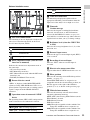
Operating and Connectors Section
FILTER selector
setting
ND filter
1CLEAR
2
1
/
4
ND (attenuates light to
approximately
1
/
4
)
3
1
/
16
ND (attenuates light to
approximately
1
/
16
)
4
1
/
64
ND (attenuates light to
approximately
1
/
64
)

Locations and Functions of Parts and Controls
18
Chapter 1 Overview
white balance setting returns to the original
setting.
If you push the switch to the BLACK side once
more during the automatic black balance
adjustment, the adjustment is cancelled and the
black balance setting returns to the original
setting.
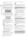
f MIC (microphone) LEVEL control
Adjusts the input level of audio channels 1, 2, 3
and 4 (see page 60).
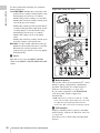
Right side (near the front)
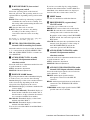
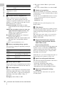
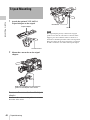
a ASSIGN. (assignable) 1/2/3 switches
You can assign the desired functions to these
switches on OPERATION >Assignable SW in
the setup menu (see page 155).
Off is assigned to the ASSIGN 1/2/3 switches as
the factory default setting.
The ASSIGN.1/3 switches are provided with an
indicator to show whether a function is assigned
to the switch (ON) or not (OFF).
b COLOR TEMP. (color temperature)
button
Press to light the button and change the color
temperature for shooting (factory default setting).
You can use this as an assignable switch (see
page 155).
c ALARM (alarm tone volume
adjustment) knob
Controls the volume of the warning tone that is
output via the built-in speaker or optional
earphones. When the knob is turned to the
minimum position, no sound can be heard.
However, if MAINTENANCE >Audio >Min
Alarm Volume in the setup menu is set to [Set],
the alarm tone is audible even when this volume
control is at the minimum position.
d MONITOR (monitor volume
adjustment) knob
Controls the volume of the sound other than the
warning tone that is output via the built-in speaker
or earphones. When the knob is turned to the
minimum position, no sound can be heard.
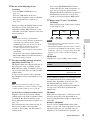
e MONITOR (audio monitor selection)
switches
By means of combinations of the two switches,
you can select audio that you want to hear through
the built-in speaker or earphones.
Position of down-side switch: CH-1/2
Position of down-side switch: CH-3/4
Position of up-side
switch
Audio output
CH-1/CH-3 Channel 1 audio
MIX Channels 1 and 2 mixed
audio (stereo)
a)
CH-2/CH-4 Channel 2 audio
Position of up-side
switch
Audio output
CH-1/CH-3 Channel 3 audio
MIX Channels 3 and 4 mixed
audio (stereo)
a)
CH-2/CH-4 Channel 4 audio
ALARM
Minimum Maximum

Locations and Functions of Parts and Controls
19
Chapter 1 Overview
a) By connecting stereo headphones to the EARPHONE
jack, you can hear the audio in stereo. (Under
MAINTENANCE >Audio in the setup menu,
Headphone Out must be set to STEREO.)
f ASSIGN. (assignable) 0 switch
You can assign the desired function to this switch
on OPERATION >Assignable SW in the setup
menu (see page 156).
Off is assigned to this switch when the camcorder
is shipped from the factory.
This is a momentary type switch. Each press of
the switch turns the function assigned to this
switch on or off.
g GAIN selector
Switches the gain of the video amplifier to match
the lighting conditions during shooting. The gains
corresponding to the L, M, and H settings can be
selected on OPERATION >Gain Switch in the
setup menu (see page 119). (The factory settings
are L=0 dB, M=6 dB, and H=12 dB.)
When this switch is adjusted, the new setting
appears on the viewfinder screen for about three
seconds.
h OUTPUT/DCC (output signal/dynamic
contrast control) switch
Switches the video signal output from the camera
module, between the following two.
BARS: Output the color bar signal.
CAM: Output the video signal being shot. When
this is selected, you can switch DCC
1)
on and
off.
1) DCC (Dynamic Contrast Control): Against a very
bright background with the iris opening adjusted to the
subject, objects in the background will be lost in the
glare. The DCC function will suppress the high
intensity and restore much of the lost detail and is
particularly effective in the following cases.
• Shooting people in the shade on a sunny day
• Shooting a subject indoors, against a background
through a window
• Any high contrast scene
i WHITE BAL (white balance memory)
switch
Controls adjustment of the white balance.
PRST: Adjust the color temperature to the preset
value (the factory default setting: 3200K).
Use this setting when you have no time to
adjust the white balance.
A or B: Recall the white balance adjustment
settings already stored in A or B. Push the
AUTO W/B BAL switch (see page 17) on
the WHITE side, to automatically adjust the
white balance, and save the adjustment
settings in memory A or memory B.
B (ATW
1)
): When this switch is set to B and
OPERATION >White Setting >White
Switch<B> is set to [ATW] in the setup
menu, ATW is activated.
You can use the AUTO W/B BAL switch
even when ATW is in use.
When this switch is adjusted, the new setting
appears on the viewfinder screen for about three
seconds.
1) ATW (Auto Tracing White Balance): The white
balance of the picture being shot is adjusted
automatically for varying lighting conditions.
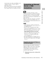
j MENU ON/OFF switch
To use this switch, open the cover.
This switch is used to display the menu on the
viewfinder screen or the test signal screen. Each
time the switch is pushed down, the menu screen
is turned on and off.
The function of this switch is the same as that of
the MENU button in the thumbnail screen
operations section.
Note
This switch has different functions depending on
whether or not a menu is displayed.
k MENU CANCEL/PRST (preset) /
ESCAPE switch
To use the MENU CANCEL/PRST/ESCAPE
switch, open the cover.
Note
It is not possible to turn off the menu screen by closing
the cover.
Use the switch in the following way when the
menu is not displayed.
CANCEL/PRST: Each time this switch is
pushed upward, a window to confirm the
menu settings and status of the camcorder
appears on the viewfinder screen (see
page 66). The window consists of five pages,
which are switched each time the switch is
pushed upward. Each page is displayed for
about 10 seconds.
ESCAPE: To clear the page immediately after
display, push this switch down to the OFF
position.

Locations and Functions of Parts and Controls
20
Chapter 1 Overview
Use the switch in the following way when the
menu is displayed.
CANCEL/PRST: Pushing this switch up to this
position after a setting is changed in the setup
menu displays the message to confirm
whether the previous settings are cancelled.
Pushing this switch up to this position again
cancels the previous settings.
Pushing this switch up to this position before
a setting is changed in the setup menu or after
a setting change is cancelled in the setup
menu displays the message to confirm
whether the setting is reset to the initial
value.
Pushing this switch up to this position again
resets the settings to the initial value.
ESCAPE: Use this switch when the menu page,
which has a hierarchical structure, is opened.
Each time the switch is pushed to this
position, the page returns to one stage higher
in the hierarchy.
l Cover
Open this cover to use the MENU ON/OFF
switch or the MENU CANCEL/PRST/ESCAPE
switch.
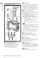
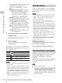
Right side (near the rear)
a Built-in speaker
The speaker can be used to monitor E-E
1)
sound
during recording, and playback sound during
playback. The speaker also sounds alarms to
reinforce visual warnings (see page 176).
If you connect earphones to the EARPHONE
jack, the speaker output is suppressed
automatically.
1) E-E: Abbreviation of “Electric-to-Electric”. In E-E
mode, video and audio signals input to the camcorder
are output after passing through internal electric
circuits only. This can be used to check input signals.
b LCD monitor
Displays remaining battery capacity, remaining
media capacity, audio levels, time data, and so on
(see page 26).
Also allows you to check camera and playback
pictures.
Page is loading ...
Page is loading ...
Page is loading ...
Page is loading ...
Page is loading ...
Page is loading ...
Page is loading ...
Page is loading ...
Page is loading ...
Page is loading ...
Page is loading ...
Page is loading ...
Page is loading ...
Page is loading ...
Page is loading ...
Page is loading ...
Page is loading ...
Page is loading ...
Page is loading ...
Page is loading ...
Page is loading ...
Page is loading ...
Page is loading ...
Page is loading ...
Page is loading ...
Page is loading ...
Page is loading ...
Page is loading ...
Page is loading ...
Page is loading ...
Page is loading ...
Page is loading ...
Page is loading ...
Page is loading ...
Page is loading ...
Page is loading ...
Page is loading ...
Page is loading ...
Page is loading ...
Page is loading ...
Page is loading ...
Page is loading ...
Page is loading ...
Page is loading ...
Page is loading ...
Page is loading ...
Page is loading ...
Page is loading ...
Page is loading ...
Page is loading ...
Page is loading ...
Page is loading ...
Page is loading ...
Page is loading ...
Page is loading ...
Page is loading ...
Page is loading ...
Page is loading ...
Page is loading ...
Page is loading ...
Page is loading ...
Page is loading ...
Page is loading ...
Page is loading ...
Page is loading ...
Page is loading ...
Page is loading ...
Page is loading ...
Page is loading ...
Page is loading ...
Page is loading ...
Page is loading ...
Page is loading ...
Page is loading ...
Page is loading ...
Page is loading ...
Page is loading ...
Page is loading ...
Page is loading ...
Page is loading ...
Page is loading ...
Page is loading ...
Page is loading ...
Page is loading ...
Page is loading ...
Page is loading ...
Page is loading ...
Page is loading ...
Page is loading ...
Page is loading ...
Page is loading ...
Page is loading ...
Page is loading ...
Page is loading ...
Page is loading ...
Page is loading ...
Page is loading ...
Page is loading ...
Page is loading ...
Page is loading ...
Page is loading ...
Page is loading ...
Page is loading ...
Page is loading ...
Page is loading ...
Page is loading ...
Page is loading ...
Page is loading ...
Page is loading ...
Page is loading ...
Page is loading ...
Page is loading ...
Page is loading ...
Page is loading ...
Page is loading ...
Page is loading ...
Page is loading ...
Page is loading ...
Page is loading ...
Page is loading ...
Page is loading ...
Page is loading ...
Page is loading ...
Page is loading ...
Page is loading ...
Page is loading ...
Page is loading ...
Page is loading ...
Page is loading ...
Page is loading ...
Page is loading ...
Page is loading ...
Page is loading ...
Page is loading ...
Page is loading ...
Page is loading ...
Page is loading ...
Page is loading ...
Page is loading ...
Page is loading ...
Page is loading ...
Page is loading ...
Page is loading ...
Page is loading ...
Page is loading ...
Page is loading ...
Page is loading ...
Page is loading ...
Page is loading ...
Page is loading ...
Page is loading ...
Page is loading ...
Page is loading ...
Page is loading ...
Page is loading ...
Page is loading ...
Page is loading ...
Page is loading ...
Page is loading ...
Page is loading ...
Page is loading ...
Page is loading ...
Page is loading ...
Page is loading ...
Page is loading ...
Page is loading ...
Page is loading ...
Page is loading ...
Page is loading ...
Page is loading ...
Page is loading ...
Page is loading ...
Page is loading ...
Page is loading ...
Page is loading ...
Page is loading ...
Page is loading ...
Page is loading ...
Page is loading ...
Page is loading ...
Page is loading ...
Page is loading ...
Page is loading ...
-
 1
1
-
 2
2
-
 3
3
-
 4
4
-
 5
5
-
 6
6
-
 7
7
-
 8
8
-
 9
9
-
 10
10
-
 11
11
-
 12
12
-
 13
13
-
 14
14
-
 15
15
-
 16
16
-
 17
17
-
 18
18
-
 19
19
-
 20
20
-
 21
21
-
 22
22
-
 23
23
-
 24
24
-
 25
25
-
 26
26
-
 27
27
-
 28
28
-
 29
29
-
 30
30
-
 31
31
-
 32
32
-
 33
33
-
 34
34
-
 35
35
-
 36
36
-
 37
37
-
 38
38
-
 39
39
-
 40
40
-
 41
41
-
 42
42
-
 43
43
-
 44
44
-
 45
45
-
 46
46
-
 47
47
-
 48
48
-
 49
49
-
 50
50
-
 51
51
-
 52
52
-
 53
53
-
 54
54
-
 55
55
-
 56
56
-
 57
57
-
 58
58
-
 59
59
-
 60
60
-
 61
61
-
 62
62
-
 63
63
-
 64
64
-
 65
65
-
 66
66
-
 67
67
-
 68
68
-
 69
69
-
 70
70
-
 71
71
-
 72
72
-
 73
73
-
 74
74
-
 75
75
-
 76
76
-
 77
77
-
 78
78
-
 79
79
-
 80
80
-
 81
81
-
 82
82
-
 83
83
-
 84
84
-
 85
85
-
 86
86
-
 87
87
-
 88
88
-
 89
89
-
 90
90
-
 91
91
-
 92
92
-
 93
93
-
 94
94
-
 95
95
-
 96
96
-
 97
97
-
 98
98
-
 99
99
-
 100
100
-
 101
101
-
 102
102
-
 103
103
-
 104
104
-
 105
105
-
 106
106
-
 107
107
-
 108
108
-
 109
109
-
 110
110
-
 111
111
-
 112
112
-
 113
113
-
 114
114
-
 115
115
-
 116
116
-
 117
117
-
 118
118
-
 119
119
-
 120
120
-
 121
121
-
 122
122
-
 123
123
-
 124
124
-
 125
125
-
 126
126
-
 127
127
-
 128
128
-
 129
129
-
 130
130
-
 131
131
-
 132
132
-
 133
133
-
 134
134
-
 135
135
-
 136
136
-
 137
137
-
 138
138
-
 139
139
-
 140
140
-
 141
141
-
 142
142
-
 143
143
-
 144
144
-
 145
145
-
 146
146
-
 147
147
-
 148
148
-
 149
149
-
 150
150
-
 151
151
-
 152
152
-
 153
153
-
 154
154
-
 155
155
-
 156
156
-
 157
157
-
 158
158
-
 159
159
-
 160
160
-
 161
161
-
 162
162
-
 163
163
-
 164
164
-
 165
165
-
 166
166
-
 167
167
-
 168
168
-
 169
169
-
 170
170
-
 171
171
-
 172
172
-
 173
173
-
 174
174
-
 175
175
-
 176
176
-
 177
177
-
 178
178
-
 179
179
-
 180
180
-
 181
181
-
 182
182
-
 183
183
-
 184
184
-
 185
185
-
 186
186
-
 187
187
-
 188
188
-
 189
189
-
 190
190
-
 191
191
-
 192
192
-
 193
193
-
 194
194
-
 195
195
-
 196
196
-
 197
197
-
 198
198
-
 199
199
-
 200
200
-
 201
201
-
 202
202
-
 203
203


Ask a question and I''ll find the answer in the document
Finding information in a document is now easier with AI
Related papers
-
Sony PDW-680 User guide
-
-
-
Sony PXW-X400 KC Operating instructions
-
-
-
-
-
protech PMW-400L Operating instructions
-
Sony PMW-200 Operating instructions
Other documents
-
Panasonic AJ-PD900W User manual
-
Canon XF105 User guide
-
JVC LYT2089-001D User manual
-
-
Roland VR-3EX Owner's manual
-
 Homder Upgrade Dash Cam Front and Rear, 7'' Monitor Front Lens User manual
-
-
JVC GY HM650E, HM650U Operating instructions
-
Canon XL H1A User manual
-
 Pixapro GLOWPAD 144SB User manual

