Page is loading ...

Soundcraft Vi Series™ User Guide Page 23 - 1
TECHNICAL INFORMATION
Vi Series Standard I/O Cards

Soundcraft Vi Series™ User GuidePage 23 - 2
D21m System
6-6 D21m Modules Date printed: 13.08.07
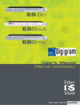
6.2.3 Line In Card 1.949.421
Eight-channel line input card with 24 bit, 44.1/48/88.2/96 kHz A/D Converter,
delta-sigma conversion. Transformer-balanced inputs. 96 kHz, 88.2 kHz, 48
kHz, or 44.1 kHz operation. 7...26 dBu input sensitivity. “Signal present”
LED indicator. Inputs on standard 25-pin D-type connector (female).
Input level (for 0 dB
FS
) 15/24 dBu ( xed, jumper-selectable),
or 7...26 dBu (adjustable)
Input impedance > 10 kΩ
Frequency response (20 Hz...20 kHz) –0.2 dB
THD&N (35 Hz...20 kHz, –1 dB
FS
, min. gain) < –97 dB
FS
(1 kHz, –30 dB
FS
, min. gain) < –111 dB
FS
Crosstalk (1 kHz) < –110 dB
Input delay (local) 38 samples (0.79 ms @ 48 kHz)
(remote) 45 samples (0.94 ms @ 48 kHz)
Current consumption (7 V) 0.42 A
(±15 V) 0.1 A
Operating temperature 0...40° C
A
D
A
D
A
D
A
D
Jumper
Trim
–2...+8 dB
15 dBu ^
=
Full Scale
Backplane Connector
Att. –9 dB
Line In 1
Line In 2
Line In 3
Line In 4
Line In 5
Line In 6
Line In 7
Line In 8
LINE IN CARD

Soundcraft Vi Series™ User Guide Page 23 - 3
D21m System
D21m Modules 6-7Date printed: 13.08.07
Jumpers: Level (Ch1...8) Two positions each: 15 dBu or 24 dBu.
LEDs: SIGNAL 1...8 For each of the eight channels a green LED indicates if input signal is present;
its brightness is a rough indication of the signal level.
Alignment: RA1...8 The multi-turn trimmer gives fine adjustment of the input level set with
the jumpers. The factory default is +22dBu in =0dBFS.
If a different input sensitivity has to be adjusted, select
the desired range with the jumper and use the LEVEL trimmer potentiometer
to adjust to the desired level.
Repeat this alignment for all inputs.
Connector Pin Assignment: (25-pin D-type, female)
Pin Signal Pin Signal
1 CH 8 in + 14 CH 8 in –
2 CH 8 in GND 15 CH 7 in +
3 CH 7 in – 16 CH 7 in GND
4 CH 6 in + 17 CH 6 in –
5 CH 6 in GND 18 CH 5 in +
6 CH 5 in – 19 CH 5 in GND
7 CH 4 in + 20 CH 4 in –
8 CH 4 in GND 21 CH 3 in +
9 CH 3 in – 22 CH 3 in GND
10 CH 2 in + 23 CH 2 in –
11 CH 2 in GND 24 CH 1 in +
12 CH 1 in – 25 CH 1 in GND
13 n.c.
Level Ch 1
Ch 1
Ch 3
Ch 2
Ch 4
Ch 5
Ch 7
Ch 6
Ch 8
Level Ch 3
Level Ch 5
Level Ch 7
24 dBu
15 dBu
24 dBu
15 dBu
Level Ch 2
Level Ch 4
Level Ch 6
Level Ch 8
1
Solder/Crimp View
(or Socket View)
13
25
14

Soundcraft Vi Series™ User GuidePage 23 - 4
D21m System
6-8 D21m Modules Date printed: 13.08.07
6.2.4 Line Out Card 1.949.420
Eight-channel, 24 bit line output card with 24 bit D/A converters with 96 kHz,
88.2 kHz, 48 kHz, or 44.1 kHz operation. Electronically balanced outputs.
7…26 dBu max. output level. Outputs on standard 25-pin D-type connector
(female).
Output level (for 0 dB
FS
) 15/24 dBu ( xed, jumper-selectable),
or 7...26 dBu (adjustable)
Output impedance 40 Ω
Min. load (at +24 dBu) 600 Ω
Frequency response (20 Hz...20 kHz) –0.2 dB
THD&N (20 Hz...20 kHz, –1 dB
FS
, jumper at 15 dBu xed) < –90 dB
FS
(1 kHz, –30 dB
FS
, jumper at 15 dBu xed) < –110 dB
FS
Crosstalk (1 kHz) < –110 dB
Output delay (local) 28 samples (0.58 ms @ 48 kHz)
(remote) 32 samples (0.67 ms @ 48 kHz)
Current consumption (7 V) 0.23 A
(±15 V) 0.25 A
Operating temperature 0...40° C
Line Out 1
Line Out 2
Line Out 3
Line Out 4
Line Out 5
Line Out 6
Line Out 7
Line Out 8
–
–
–
–
–
–
–
–
Jumper
+9 dB
Trim
D
D
D
–8...+2 dB
15 dBu ^
=
Full Scale
Backplane Connector
D
A
A
A
A
LINE OUT CARD

Soundcraft Vi Series™ User Guide Page 23 - 5
D21m System
D21m Modules 6-9Date printed: 13.08.07
Jumpers: Level (Ch1...8) Two positions each: 15 dBu (factory default) or 24 dBu.
Alignment: RA1...8 The multi-turn trimmer gives fine adjustment of the output level set with
the jumpers. The factory default is +22dBu out = 0dBFS.
If a different output level is required, select the desired range
with the jumper and use the LEVEL trimmer potentiometer to adjust to the
desired level.
Repeat this alignment for all outputs.
Connector Pin Assignment: (25-pin D-type, female)
Pin Signal Pin Signal
1 CH 8 out + 14 CH 8 out –
2 CH 8 out GND 15 CH 7 out +
3 CH 7 out – 16 CH 7 out GND
4 CH 6 out + 17 CH 6 out –
5 CH 6 out GND 18 CH 5 out +
6 CH 5 out – 19 CH 5 out GND
7 CH 4 out + 20 CH 4 out –
8 CH 4 out GND 21 CH 3 out +
9 CH 3 out – 22 CH 3 out GND
10 CH 2 out + 23 CH 2 out –
11 CH 2 out GND 24 CH 1 out +
12 CH 1 out – 25 CH 1 out GND
13 n.c.
Level
Ch 1
24 dBu
15 dBu
Level
Ch 3
24 dBu
15 dBu
Level
Ch 5
24 dBu
15 dBu
Level
Ch 7
24 dBu
15 dBu
Level
Ch 2
24 dBu
15 dBu
Level
Ch 4
24 dBu
15 dBu
Level
Ch 6
24 dBu
15 dBu
Level
Ch 8
24 dBu
15 dBu
1
Solder/Crimp View
(or Socket View)
13
25
14

Soundcraft Vi Series™ User GuidePage 23 - 6
D21m System
6-2 D21m Modules Date printed: 13.08.07
6.2 Analog I/O Cards
6.2.1 Mic/Line In Card 1.949.427
Four analog microphone/line inputs, electronically balanced, with 24 bit,
44.1/48/88.2/96 kHz delta-sigma A/D converters (mic/line sensitivity, gain
setting in 1 dB steps, low-cut lter, soft clipping and 48 V phantom power on/
off controlled by console software); four analog split outputs (not used)
electronically balanced. Green “signal present” and yellow “phantom
power” indicators per channel. Inputs and split outputs on standard 25-pin
D-type connector (female).
Input sensitivity (for 0 dB
FS
) –60…+26 dBu
Input impedance 1.8 kΩ
Equivalent input noise (R
i
200 Ω, max. gain) –124 dBu
Crosstalk (1 kHz) < –110 dB
Frequency response (30 Hz...20 kHz) –0.2 dB
THD&N (35 Hz...20 kHz, –1 dB
FS
, min. gain) < –97 dB
FS
(1 kHz, –30 dB
FS
, min. gain) < –111 dB
FS
(input level 6 dBu, min. gain) < –107 dB
FS
CMRR (30 Hz...20 kHz, all gain settings) > 55 dB
(1 kHz, input sensitivity –10...+26 dBu for 0 dB
FS
) typ. 100 dB
Low-cut lter 75 Hz / 12 dB/oct.
Input delay (local) 38 samples (0.79 ms @ 48 kHz)
(remote) 45 samples (0.94 ms @ 48 kHz)
Current consumption (7 V) 0.2 A
(±15 V) 0.25 A
Operating temperature 0...40° C
Backplane Connector
Mic/Line In 1
A
D
48 V Phantom Pwr
0 dB*
–20 dB*
A
D
0 dB*
–20 dB*
0 dB*
–20 dB*
0 dB*
–20 dB*
* 0 dB for input sensitivity –60...+3 dBu, –20 dB for input sensitivity +4...+26 dBu
Mic/Line In 2
Mic/Line In 3
Mic/Line In 4
Split out 1
Split out 2
Split out 3
Split out 4
Control Logic
Sensitivity
–60...+26 dBu
INS
INS
INS
INS
Insert Connector
Sensitivity Control
High-Pass Filter Insert Control
MIC/LINE IN CARD

Soundcraft Vi Series™ User Guide Page 23 - 7
D21m System
D21m Modules 6-3Date printed: 13.08.07
LEDs: PHANTOM 1...4 For each channel a yellow LED indicates if the pantom supply is on.
SIGNAL 1...4 For each channel a green LED indicates if input signal is present; its bright-
ness is a rough indication of the signal level.
Alignment: RA1...4 Please note that the input level trimmer potentiometers are factory-set. They
need to be adjusted only after having repaired the card.
Select 15 dBu input sensitivity. Feed an analog signal with a level of +6 dBu
to one of the analog inputs. Measure the digital output level either on the
MADI output or, after routing through the core, on one of the AES/EBU
outputs. Adjust the level with the corresponding FINE ADJUST trimmer
potentiometer to –9 dB
FS
.
Connector Pin Assignment: (25-pin D-type, female)
Pin Signal Pin Signal
1 CH 4 split out + 14 CH 4 split out –
2 CH 4 split out GND 15 CH 3 split out +
3 CH 3 split out – 16 CH 3 split out GND
4 CH 2 split out + 17 CH 2 split out –
5 CH 2 split out GND 18 CH 1 split out +
6 CH 1 split out – 19 CH 1 split out GND
7 CH 4 in + 20 CH 4 in –
8 CH 4 in GND 21 CH 3 in +
9 CH 3 in – 22 CH 3 in GND
10 CH 2 in + 23 CH 2 in –
11 CH 2 in GND 24 CH 1 in +
12 CH 1 in – 25 CH 1 in GND
13 n.c.
Important! If wired correctly, the microphones are isolated from the Local Rack chassis.
The circuit inside the microphone takes its supply from pins 2 and 3 (+ and –)
for the positive, and from pin 1 (GND) for the negative reference. If a patch bay
is implemented, GND (pin 1 on XLR connector) of each microphone input
must be connected to its corresponding GND pin, but not to the chassis. If
chassis instead of GND is used as negative reference for a microphone, it can
occur that the GND net of the Local Rack is pulled towards –48 V. This causes
the HD link receivers not to work correctly or to be damaged, depending on
the type and number of microphones connected.
As a workaround, GND and chassis may be connected inside the Local Rack.
frame. In cases where currents ow between the chassis nets of multiple devices,
the analog signals can degrade in quality (e.g. perceivable as hum).
RA1
RA2
RA3
RA4
RA1...4: Factory Setting (Level Fine-Adjustment)
1
Solder/Crimp View
(or Socket View)
13
25
14

Soundcraft Vi Series™ User GuidePage 23 - 8
D21m System
6-10 D21m Modules Date printed: 30.08.07
6.3 Digital I/O Cards
6.3.1 AES/EBU I/O Cards 1.949.422, 1.949.423, 1.949.424
AES/EBU input/output card with 16 Ch I/O.
With input SFCs only.
Selectable output sampling frequencies:
96 kHz, 48 kHz, 44.1 kHz, or external reference (22...108 kHz). Input SFCs
can be bypassed individually.
Output dither is selectable for every AES/EBU output from 24 bit, 20 bit,
18 bit or 16 bit. Settings are made with jumpers. Inputs and outputs on stan-
dard 25-pin D-type connectors (female).
SFC Delay: Enabled input and output SFCs each cause a delay (D) that depends on the
SFC’s input and output sampling frequency (f
S_IN
and f
S_OUT
). Input and output
delays can be calculated using the formulas below.
[2] f
S_OUT
> f
S_IN
: D =
48
f
S_IN
[s]
[1] f
S_IN
> f
S_OUT
: D =
16
f
S_IN
+ [s]
32
f
S_OUT
Examples:
• For a 96 kHz input signal and a 48 kHz system clock (i.e., the “output signal”
of the input SFC), the input delay is 40 output samples or 0.833 ms (formula
“1”).
• For a 48 kHz system clock (i.e., the “input signal” of the output SFC) and a
96 kHz output signal, the output delay is 96 output samples or 1 ms (formula
“2”).
Note: If the core is operating with a 44.1 or 88.2 kHz system clock, the output sam-
pling frequency will be 44.1 or 88.2 kHz, regardless of the jumper selection
– unless the external sync input is used and Ext. is selected; then, the output
sampling frequency corresponds to the one of the external sync signal.
Backplane Connector
Clock Selector 1 *
96 k, 48 k, 44.1 k, ext.
* for 1.949.424.xx only ** for 1.949.423.xx and 1.949.424.xx only
Clock Selector 2 *
96 k, 48 k, 44.1 k, ext.
AES Tx
AES Tx
AES Tx
AES Tx
AES Tx
AES Tx
AES Tx
AES Rx *
AES Tx
AES Rx
AES Rx
AES Rx
AES Rx
AES Rx
AES Rx
AES Rx
AES Rx
AES Out 1
AES Out 2
AES Out 3
AES Out 4
AES Out 6
AES Sync In *
AES Out 8
AES Out 7
AES Out 5
AES In 1
AES In 6
AES In 3
AES In 5
AES In 4
AES In 2
AES In 7
AES In 8
SFC *
SFC **
SFC *
SFC *
SFC *
SFC *
SFC *
SFC *
SFC *
SFC **
SFC **
SFC **
SFC **
SFC **
SFC **
SFC **
AES/EBU I/O CARDS
Note: Output SFCs are not tted on the Vi4/6.

Soundcraft Vi Series™ User Guide Page 23 - 9
D21m System
D21m Modules 6-11Date printed: 30.08.07
Input / output impedance 110 Ω
Input sensitivity min. 0.2 V
Output level (into 110 Ω) 5 V
SFC range 22...108 kHz
Current consumption (3.3 V) 1.949.422: 0.2 A; ..423: 0.4 A; ..424: 0.6 A
(5 V) 0.65 A
Operating temperature 0...40° C
Input SFC*
Enabled
Bypassed
*
1.949.423 and 1.949.424 only
**
1.949.424 only (see Note 1)
Ch 1
Ch 2
Ch 3
Ch 4
Ch 5
Ch 6
Ch 7
Ch 8
Output Word Length**
24 Bit 20 Bit
18 Bit 16 Bit
Output Sampling Rate**
Ch 4
Ch 3
Ch 8
Ch 7
Ch 6
Ch 5
Ch 2
Ch 1
Ch 5...8
Ch 1...4
Ch 5...8
96 k Ext.
Output SFC**
Bypassed
Enabled
Ch 1...4
48 k 44.1 k
LEDs: LOCK 1...8 These green LEDs are on if a valid AES/EBU signal is available at the
inputs.
Jumpers:
Input SFC Enabling or bypassing of the SFCs for individual AES/EBU input channels.
Output Sampling frequency (1.949.424 only) The output sampling frequency may be set for the AES/
EBU output channel groups 1...4 and 5...8; selection from 44.1 kHz, 48 kHz,
96 kHz, or synchronized by the signal at the AES EXT SYNC IN connector
(see “Note” above).
If no valid signal is provided at the AES EXT SYNC IN connector but Ext.
is selected, the output sampling frequency will be set to the system clock.
Outputs set to Ext. can therefore be used in a very exible way: Connect no
external sync signal, if not necessary, so that the output will be clocked with
the internal system clock. As soon as an external sync signal is provided to
the AES EXT SYNC IN connector, the output will be clocked with the ext.
sync signal.
Output SFC / WL Reduction (1.949.424 only) Enabling/bypassing of the output SFCs, separate for the
AES/EBU output channel groups 1...4 and 5...8. Please note that for word
length reduction the output SFCs must be set to Enabled.

Soundcraft Vi Series™ User GuidePage 23 - 10
D21m System
6-12 D21m Modules Date printed: 30.08.07
Connector Pin Assignment: (2 × 25-pin D-type, female)
Pin Signal “CH 1...8” Signal “CH 9...16” Pin Signal “CH 1...8” Signal “CH 9...16”
1 CH 7/8 out + CH 15/16 out + 14 CH 7/8 out – CH 15/16 out –
2 CH 7/8 out screen CH 15/16 out screen 15 CH 5/6 out + CH 13/14 out +
3 CH 5/6 out – CH 13/14 out – 16 CH 5/6 out screen CH 13/14 out screen
4 CH 3/4 out + CH 11/12 out + 17 CH 3/4 out – CH 11/12 out –
5 CH 3/4 out screen CH 11/12 out screen 18 CH 1/2 out + CH 9/10 out +
6 CH 1/2 out – CH 9/10 out – 19 CH 1/2 out screen CH 9/10 out screen
7 CH 7/8 in + CH 15/16 in + 20 CH 7/8 in – CH 15/16 in –
8 CH 7/8 in screen CH 15/16 in screen 21 CH 5/6 in + CH 13/14 in +
9 CH 5/6 in – CH 13/14 in – 22 CH 5/6 in screen CH 13/14 in screen
10 CH 3/4 in + CH 11/12 in + 23 CH 3/4 in – CH 11/12 in –
11 CH 3/4 in screen CH 11/12 in screen 24 CH 1/2 in + CH 9/10 in +
12 CH 1/2 in – CH 9/10 in – 25 CH 1/2 in screen CH 9/10 in screen
13 n.c. n.c.
1
Solder/Crimp View
(or Socket View)
13
25
14

Soundcraft Vi Series™ User Guide Page 23 - 11
D21m System
D21m Modules 6-13Date printed: 30.08.07
6.3.2 MADI I/O Cards 1.949.430, 1.949.431, 1.949.433
The MADI I/O card can establish a 64-channel MADI input and output to the
Stagebox or other MADI-equipped device. Optical inputs and out puts
are provided on SC connectors available in multi-mode and single-mode ver-
sions, as well as a version with RJ45 connectors for twisted-pair cable and an
additional word clock output on a BNC socket.
The auxiliary interface can be used as a redundant link.
It is possible to transmit any serial control signals, such as MIDI or Sony 9-
pin (machine control) through a MADI connection without losing any audio
bandwidth or microphone control of the remote I/O box. For this purpose, an
RS422 connector is located on this card (hub frame side). The desired baud
rate can be set with a rotary switch. The pinout of the RS422 connector can
be set to “device” or “controller” with a DIP switch, depending on the 3rd
party serial device connected.
Max. cable length multi-mode bre, 1300 nm 2 km
single-mode bre, 1300 nm 15 km
CAT5e or better, exible braid <75 m
CAT7, solid core <120 m
Input frequencies 48kHz ±100 ppm
Current consumption (3.3 V) 0.4 A
(5 V) 0.4 A
Operating temperature 0...40° C
Lock LED
RX
Dual MADI Decoder
Dual MADI Encoder
RS422
RX/TX
Backplane Connector
Lock LED
MADI In 1
MADI In 2
MADI Out 1
MADI Out 2
RX
TX
TX
RS422
Port
UART to Merger Card
0...64 Ch
0...64 Ch
UART from Merger Card
User UART
MADI I/O CARDS

Soundcraft Vi Series™ User GuidePage 23 - 12
D21m System
6-14 D21m Modules Date printed: 30.08.07
S3
S5
S4
12345678
*S1
*S2
12345678
1 2 3 4 5 6 7 8
ON
Default
Setting:
ON
Default Setting:
MADI I/O Card, Optical Versions
Default
Setting:
Default
Setting:
Default
Setting:
ON
ON
ON
12345678
12345678
1234567812345678
S3
S5** S1
S4
MADI I/O Card, Twisted-Pair Version
Switches: *S1 (On optical versions only)
Toggle switch for 64 (factory default) or 56 channel selection.
**S1 (On Cat5 version only)
In case of connecting two cores, they must be synchronized. The twisted-pair
cable version of the MADI card provides a reserved wire pair for both the
main and aux RJ45 sockets on which the sync signal can be transferred. The
sync transfer direction (from master to slave) is set using the DIP switches
S1 and S4.7/.8. Please note that in such a case the twisted-pair wiring has to
be done with a crossover cable. On the slave core, the WCLK output must be
patched to the WCLK input of the audio clock card.
(refer to the block diagram on the opposite page)
12345678Setting
OFF OFF OFF OFF ON ON ON ON
Card is Master (factory default)
ON ON ON ON OFF OFF OFF OFF Card is Slave
NO OTHER SETTINGS ALLOWED !

Soundcraft Vi Series™ User Guide Page 23 - 13
D21m System
D21m Modules 6-15Date printed: 30.08.07
MADI
MAIN
(RJ45)
ACTIVE IF
FS_SYS
MADI
AUX
(RJ45)
S1.1
Reserved pairs
for FS Sync
transmission
S1.2
S1.5
S1.6
S1.3
S1.4
S1.7
S1.8
Backplane Connector
WCLK
OUT
1
0
S4.7
S4.8
*S2 (On optical versions only)
Rotary switch for baud rate selection of the RS422 user interface:
Position Setting
0 115’200 bps (factory default)
1 57’600 bps
2 38’400 bps (9-pin)
3 31’250 bps (MIDI)
4 19’200 bps
5 9’600 bps
6...9 Reserved for future use
S3 DIP switch for D21m channel count setting:
1 2 3 4 5 6 7 8 Number of Channels
ON ON ON ON - - - -
0 inputs
ON ON ON OFF - - - -
8 inputs
ON ON OFF ON - - - -
16 inputs
ON ON OFF OFF - - - -
24 inputs
ON OFF ON ON - - - -
32 inputs
ON OFF ON OFF - - - -
40 inputs
ON OFF OFF ON - - - -
48 inputs
ON OFF OFF OFF - - - -
56 inputs
OFF ON ON ON - - - -
64 inputs (factory default)
OFF
:
OFF
ON
:
OFF
ON
:
OFF
OFF
:
OFF
-
-
-
-
-
-
-
-
-
-
-
-
NOT ALLOWED
- - - - ON ON ON ON
0 outputs
- - - - ON ON ON OFF
8 outputs
- - - - ON ON OFF ON
16 outputs
- - - - ON ON OFF OFF
24 outputs
- - - - ON OFF ON ON
32 outputs
- - - - ON OFF ON OFF
40 outputs
- - - - ON OFF OFF ON
48 outputs
- - - - ON OFF OFF OFF
56 outputs
- - - - OFF ON ON ON
64 outputs (factory default)
-
-
-
-
-
-
-
-
-
-
-
-
OFF
:
OFF
ON
:
OFF
ON
:
OFF
OFF
:
OFF
NOT ALLOWED

Soundcraft Vi Series™ User GuidePage 23 - 14
D21m System
6-16 D21m Modules
Date printed: 30.08.07
S4 DIP switch for MADI setting (on the Cat5 version the switches 4...8 are
used differently, as indicated below):
Card Versions Switch Setting
ALL MADI Cards
1
OFF: AUX IF is used for channel extension at 96 kHz (factory default)
ON: AUX IF is used for redundancy at 96 kHz
(in 48 kHz mode, AUX IF is used for redundancy regardless of the switch setting)
2, 3
Both OFF: Standard operation (factory default)
Both ON: No communication on system UART (used for Hub-Hub interconnec-
tion)
One ON and one OFF: NOT ALLOWED.
Optical Versions only
(RS2426)
4...7
Must be set to OFF (factory default)
8
Not used (factory default: OFF)
Twisted-Pair Cable
Version only
(RS2409)
4 5 6 Baud Rate
OFF OFF OFF 115’200 bps (factory default)
OFF OFF ON 57’600 bps
OFF ON OFF 38’400 bps (9-pin)
OFF ON ON 31’250 bps (MIDI)
ON OFF OFF 19’200 bps
ON OFF ON 9’600 bps
ON
...
ON
...
OFF
...
Reserved for future use
7 8 Setting (refer to
**S1
above)
ON OFF BNC output carries system word clock (factory default)
OFF ON BNC output carries received word clock
S5 DIP switch for RS422 pinout selection:
12345678Setting
OFF OFF OFF OFF ON ON ON ON
RS422 Controller pinout
ON ON ON ON OFF OFF OFF OFF
RS422 Device pinout (factory
default)
NO OTHER SETTINGS ALLOWED!
Connector Pin Assignments: CTRL (9-pin D-type, female)
Pin RS422 Controller RS422 Device
1
Chassis Chassis
2
RxD – TxD –
3
TxD + RxD +
4
GND GND
5
n.c. n.c.
6
GND GND
7
RxD + TxD +
8
TxD – RxD –
9
Chassis Chassis
MADI MAIN / MADI AUX (8-pin RJ45) (on Cat5 version only)
Pin Signal
1 MADI TxD +
2 MADI TxD –
3 MADI RxD +
4 WCLK TXD/RXD +
5 WCLK TXD/RXD –
6 MADI RxD –
7 reserved
8 reserved
LEDs: On if a valid MADI signal is available at the input that is locked to the system
clock.
1
5
9
6
Solder/Crimp View
(or Socket View)
1
8
Socket View

Soundcraft Vi Series™ User Guide Page 23 - 15
D21m System
6-44 D21m Modules Date printed: 30.08.07
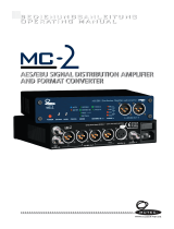
6.5.3 MADI HD Cards 1.949.411, 1.949.413, 1.949.414
The MADI HD card is plugged into the HD card slot in the Stagebox
and provides the link to the Local Rack frame. The two interfaces offer up to
64 audio channels with 48kHz operation, together with embedded
control and user-accessible serial connection in each direction.
The auxiliary interface can be used as a redundant link.
In slave mode, the card extracts the system clock from the incoming MADI
signals and provides it to the entire remote I/O box. It detects all other I/O
cards that are inserted into the Stagebox and displays their presence on
the front panel of the frame. Once all audio interface cards are plugged in,
pressing the RECONFIG key on the front panel con rms the con guration to
the system. Then all cards are activated and their audio signals are fed into
the MADI link.
Cat5 only
FS Sync
AUX to MAIN
Sync out
CH1...32 out
CH33...64 out
UART1 out
UART2 out
Sync out
CH1...32 out
CH33...64 out
UART1 out
UART2 out
Sync in
CH1...32 in
CH33...64 in
UART1 in
UART2 in
out
to D21m
Backplane
D21m card
control signals
UART
in
from D21m
Backplane
Sync in
CH1...32 in
CH33...64 in
UART1 in
UART2 in
FS Sync
MAIN to AUX
MADI in
MADI in
MADI out
CH 1...32 in
Ch 33...64 in
CH 1...32 out
Ch 33...64 out
Ctrl
Ctrl
MADI out
Mode
56CH MODE
96k
CH Ext.
96k CH Ext.
MASTER/nSLAVE
UART MODE 1
UART MODE 0
UART
MODE 1
UART MODE 0
or UART MODE 1
UART MODE 1
96k/n48k
MASTER IF
0
1
0
1
0
1
0
1
0
1
0
1
0
1
0
1
0
1
0
1
0
1
1
0
1
0
1
0
1
0
MASTER IF
MASTER IF
MASTER IF
MASTER IF
SPLIT MODE
MASTER AUX
SPLIT MODE
MASTER MAIN
56CH MODE
Mode
MADI
Decoder
Sync
Generator
Selector and
Demultiplexer
Selector and
Multiplexer
EEPROM
(D21m Command
Field Parameters)
Microcontroller
MADI
Decoder
MADI
Encoder
MADI
Encoder
MADI
Port
AUX
MADI
Port
MAIN
RS422
Port
Pinout
Selector
MADI HD CARDS

Soundcraft Vi Series™ User GuidePage 23 - 16
D21m System
D21m Modules 6-45Date printed: 30.08.07
Cable length multi-mode bre <2 km
single-mode bre <15 km (<40 km on request)
CAT5e or better, exible braid <75 m
CAT7, solid core <120 m
Input frequency 48kHz ±100 ppm
Current consumption (3.3 V/5 V) 0.9 A/0.25 A
Operating temperature 0...40° C
Optical
ON
8765432187654321
S1 S2
Cat5
ON
8765432187654321
S5
S1 S2
ON
87654321
LEDs: On if a valid MADI signal is present at the input.
Switches: S1 DIP switch for pinout selection of the front-panel RS422 connector:
12345678
ON ON ON ON OFF OFF OFF OFF
Device pinout
OFF OFF OFF OFF ON ON ON ON
Controller pinout (factory default)
NO OTHER SETTINGS ALLOWED!

Soundcraft Vi Series™ User Guide Page 23 - 17
D21m System
6-46 D21m Modules Date printed: 30.08.07
S2 DIP switch for MADI setting:
Switch Setting
1
OFF: AUX is used as redundant port at 88.2 / 96 kHz (factory default)
ON: AUX is used as CH33...64 at 88.2 / 96 kHz
2
OFF: 64 MADI channels (factory default)
ON: 56 MADI channels (standard setting for legacy products)
3, 4
34
OFF OFF MADI1 – Microcontroller / MADI 2 – Front connector (factory default)
ON OFF MADI1 – Microcontroller / MADI 2 – Backplane
OFF ON Microcontroller – Front connector / MADI 2 – Backplane
ON ON MADI1 – Front connector / MADI 2 – Backplane
[Block diagram: UART MODE 1]
[Block diagram: UART MODE 0]
5
OFF: Slave – clock from MADI signal (factory default)
[Block diagram: MASTER/nSLAVE = 0]
ON: Master – clock from local generator [Block diagram: MASTER/nSLAVE = 1]
6
OFF: Master mode sampling frequency 48 kHz (factory default)
[Block diagram: 96k/n48k = 0]
ON: Master mode sampling frequency 96 kHz [Block diagram: 96k/n48k = 1]
7, 8
reserved (factory default: OFF)
S3 3-position toggle switch for input selection (MAIN / REDundant / AUX).
MAIN: MADI input is forced to MAIN port (split mode master AUX = 0)
RED: MADI input is used from either MAIN or AUX port
AUX: MADI input is forced to AUX Port (split mode master MAIN = 1).
S4 Rotary switch for baud rate selection of the MADI 2 link:
Position Setting
0 115’200 bps (factory default)
1 57’600 bps
2 38’400 bps (9-pin)
3 31’250 bps (MIDI)
4 19’200 bps
5 9’600 bps
6...9 Reserved for future use
S5 DIP switch for FS Sync forward selection (Cat5 only):
12345678
OFF OFF OFF OFF OFF OFF OFF OFF No forward (factory default)
ON ON ON ON OFF OFF OFF OFF Main to AUX
OFF OFF OFF OFF ON ON ON ON AUX to Main
NO OTHER SETTINGS ALLOWED!
Connector Pin Assignments: RS422 (9-pin D-type, female)
Pin RS422 Controller RS422 Device
1 Chassis Chassis
2 RxD – TxD –
3 TxD + RxD +
4 GND GND
5 n.c. n.c.
6 GND GND
7 RxD + TxD +
8 TxD – RxD –
9 Chassis Chassis
1
5
9
6
Solder/Crimp View
(or Socket View)

Soundcraft Vi Series™ User GuidePage 23 - 18
D21m System
D21m Modules 6-47Date printed: 30.08.07
MADI MAIN / MADI AUX (8-pin RJ45)
(on twisted-pair cable version only)
Pin Signal
1 MADI RxD +
2 MADI RxD –
3 MADI TxD +
4 WCLK TxD/RxD +
5 WCLK TxD/RxD –
6 MADI TxD –
7 reserved
8 reserved
1
8
Socket View

Soundcraft Vi Series™ User Guide Page 23 - 19
D21m System
6-38 D21m Modules Date printed: 30.08.07
6.4.2 GPIO Card with Relay Outputs 1.949.436
For general-purpose applications requiring total electrical isolation, this card
provides 16 electrically isolated opto-coupler inputs with integrated current
sink (5...24 V
DC
) and 16 electrically isolated outputs using SPST relay con-
tacts. 5 V
DC
supply pins are available. Inputs and outputs on standard 37-pin
D-type connectors (female).
Current consumption (5 V) 0.8 A max. (earlier version: 1.1 A max.)
Operating temperature 0...40° C
Output contact rating 0.5 A/125 V
AC
; 0.7 A/30 V
DC
; 0.3 A/100 V
DC
Backplane Connector
16 × Opto In
i
LED
16
16
16 × Relay Out
GPIO CARD WITH RELAY OUTPUTS

Soundcraft Vi Series™ User GuidePage 23 - 20
D21m System
D21m Modules 6-39Date printed: 30.08.07
Connector Pin Assignment: (37-pin D-type, female)
Pin Signal “GPI 1-16” Signal “GPO 1-16” Pin Signal “GPI 1-16” Signal “GPO 1-16”
1 GPI 1a GPO 1a 20 GPI 1b GPO 1b
2 GPI 2a GPO 2a 21 GPI 2b GPO 2b
3 GPI 3a GPO 3a 22 GPI 3b GPO 3b
4 GPI 4a GPO 4a 23 GPI 4b GPO 4b
5 GPI 5a GPO 5a 24 GPI 5b GPO 5b
6 GPI 6a GPO 6a 25 GPI 6b GPO 6b
7 GPI 7a GPO 7a 26 GPI 7b GPO 7b
8 GPI 8a GPO 8a 27 GPI 8b GPO 8b
9 GPI 9a GPO 9a 28 GPI 9b GPO 9b
10 GPI 10a GPO 10a 29 GPI 10b GPO 10b
11 GPI 11a GPO 11a 30 GPI 11b GPO 11b
12 GPI 12a GPO 12a 31 GPI 12b GPO 12b
13 GPI 13a GPO 13a 32 GPI 13b GPO 13b
14 GPI 14a GPO 14a 33 GPI 14b GPO 14b
15 GPI 15a GPO 15a 34 GPI 15b GPO 15b
16 GPI 16a GPO 16a 35 GPI 16b GPO 16b
17 GND (0 V) GND (0 V) 36 V
CC
(+5 V) * V
CC
(+5 V) *
18 GND (0 V) GND (0 V) 37 V
CC
(+5 V) * V
CC
(+5 V) *
19 GND (0 V) GND (0 V) * 600 mA max. total
Application: Inputs Control inputs (GPI Xa/b) are completely independent and electrically iso-
lated. They may be used either with the internal +5 V
DC
supply voltage, or
with external voltages of 5...24 V
DC
, regardless of the polarity. Total current
supplied by all +5 V
DC
pins of one card must not exceed 600 mA.
Outputs Control outputs (GPO Xa/b) are completely independent, electrically isolated
relay contacts, closed if active. Contact rating is 0.5 A for 125 V
AC
, 0.7 A for
30 V
DC
, or 0.3 A for 100 V
DC
. The +5 V
DC
supply voltage or the ground (GND)
terminals, together with the relay contacts, may be used to generate an output
signal. Total current supplied by all +5 V
DC
pins of one card must not exceed
600 mA.
Solder/Crimp View
(or Socket View)
1
19
37
20
/