Page is loading ...

IP BUDDY+ HDoC
CVI/TVI/AHD, IP & ANALOG TEST METER
WITH VIDEO MONITOR & MULTI METER
Part number: ST-HDoC-TEST-MM
USER MANUAL v. 1.12.17.15
www.nacebrands.com www.securitytronix.com

Thank you for purchasing the SecurityTronix IP BUDDY+ HDoC CVI/TVI/AHD, Analog and IP camera monitor with network tester!
To use the IP BUDDY+ HDoC safely, please read the Safety Information carefully.
This manual should be kept with the IP BUDDY+ HDoC for reference.
Keep the serial number label for after-sale service within the warranty period. Please see the last page of the manual for warranty
information.
Batteries come disconnected to ensure they do not drain during shipment. Please connect the battery prior to powering on the IP BUDDY+
HDoC.
If you have any questions or problems while using the IP BUDDY+ HDOC camera tester, please contact our SecurityTronix technical
support department at 1-800-688-9282, option 3, then option 2.
Visit our website http://www.securitytronix.com for additional information.

Table of Contents
1. Safety information .............................................................................................................. 1
2. IP BUDDY+ HDoC Introduction ....................................................................................... 1
2.1 General .......................................................................................................................... 1
2.2 Features ......................................................................................................................... 1
2.3 Function ........................................................................................................................ 2
2.4 Packing list .................................................................................................................... 5
2.5 Operational buttons and description of connections. ..................................................... 6
3. Operation ............................................................................................................................ 8
3.1 Installing the Battery ..................................................................................................... 8
3.2 Instrument connection ................................................................................................... 8
3.2.1 IP camera connection ....................................................................................... 8
3.2.2 Coaxial camera connection .............................................................................. 9
3.3 OSD menu ....................................................................................................................... 9
3.3.1 PTZ (Activates analog video viewing and testing) ................................................ 9
3.3.2 Color-bar generator (TV OUT) ............................................................................ 13
3.3.3 CVI camera test ................................................................................................... 14
3.3.4 TVI camera test ................................................................................................... 16
3.3.5 AHD camera test ................................................................................................. 17
3.3.6 ONVIF IP camera tester ...................................................................................... 18
3.3.7 IP camera test ...................................................................................................... 22
3.3.8 IP address scanner ............................................................................................... 23
3.3.9 PING Test ............................................................................................................ 24

3.3.10 Cable test ........................................................................................................... 24
3.3.11 Port flashing....................................................................................................... 25
3.3.12 Data monitor ...................................................................................................... 25
3.3.13 Media Player ...................................................................................................... 25
3.3.14 Audio player ...................................................................................................... 26
3.3.15 LED lamp (Flashlight) ....................................................................................... 26
3.3.16 PoE in line Voltage test ..................................................................................... 27
3.3.17 Calculator .......................................................................................................... 27
3.3.18 Browser ............................................................................................................. 27
3.3.19 IP camera viewer ............................................................................................... 28
3.3.20 PoE power / 12VDC 2A and 5VDC 2A USB power output .............................. 28
3.3.21 Application tools ................................................................................................ 29
3.3.22 Digital Multi Meter ............................................................................................ 32
3.3.23 Tool Folder ........................................................................................................ 35
3.4 System Settings .............................................................................................................. 35
3.5 Update ............................................................................................................................ 37
3.6 Audio test ....................................................................................................................... 37
3.7 HDMI output ................................................................................................................. 37
3.8 PoE power output ........................................................................................................... 38
3.9 12VDC 2A power output ............................................................................................... 38
3.10 USB 5VDC 2A power output ....................................................................................... 39
4. Specifications ................................................................................................................... 40
5. SecurityTronix IP BUDDY+ HDoC Warranty ................................................................. 41

1
1. Safety information
◆ The IP BUDDY+ HDOC is intended for use in compliance with applicable codes and laws.
◆ Do not expose to moisture.
◆ Do not drop.
◆ The tester should not be charged over 8 hours.
◆ The tester should not be used in an environment with any flammable gas or chemicals.
◆ Do not disassemble the IP BUDDY+ HDOC meter except to change the battery.
◆ Don’t use any chemical cleaning products to clean the test meter. Use a dry cloth.
1.1 Digital Multi-meter Safety
◆ Prior to taking any measurements, be sure you are using the correct range, function and input jack. Red is positive, black is negative.
◆ Never exceed the protection limit value for each range of measurement.
◆ While measuring a live circuit, do not touch any unused terminals.
◆ If the value to be measured is unknown while using the manual range, set the range selector to the highest position.
◆ Always be careful when working with AC or DC voltages since you could be injured or killed by voltage going through your body. Keep your
fingers behind the probe barriers while measuring. Do not touch the metal probes while taking any measurements.
◆ Never perform any capacitance measurements unless the capacitor has been fully discharged.
2. IP BUDDY+ HDOC Description
2.1 General
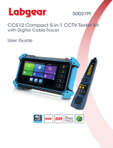
The 7 inch touch screen IP camera monitor and tester is designed for maintenance and installation of HD over Coax cameras, IP cameras and
analog cameras as well as other security equipment. The 1024×600 resolution enables it to display HD cameras and analog cameras in high
resolution. The unit supports many HD over Coax PTZ, ONVIF PTZ and analog PTZ control.
The tester is also a great tool for Ethernet network testing. It can test PoE power voltage, PING, and IP address searching. You can use the blue
cable tracer to locate individual connected cables from a bundle of cables. Test LAN cable for proper connection termination. Other functions
include providing 24W PoE power to your camera, LED Flashlight, 12VDC 2A power output and much more. Its portability, user-friendly design
and many other functions make the IP BUDDY+ HDOC an essential tool for all installers or technicians.
2.2 Features
Easy to operate 7 inch 1024×600 touch screen.
ONVIF IP camera video testing.
Compatible with H.264/MPEG4/MJPEG IP cameras, such as SecurityTronix, Dahua, HIKVISION, and ACTI.
HD CVI, HD TVI & AHD camera image display featuring zoom, video record, snapshot and PTZ control over coax.
Built in Wi-Fi: receives video from wireless cameras or ONVIF cameras connected to the network.
HDMI signal output supports up to 1080P.
Analog camera video display: Auto adapts and displays the video in NTSC/PAL formats.
Supports more than 30 PTZ protocols such as PELCO-P, PELCO-D, and SAMSUNG.
Video digital zoom to view the image in greater detail.
Snapshot function allows you to save the current image as a JPG file in the SD card.
Video recording and playback.
LED Flashlight.

2
4GB Micro SD card included.
LCD screen with adjustable brightness/contrast/color/saturation.
Enhanced Color bar generator: PAL/NTSC multi-system color bar video generator (Eight-system switchable, transmit/receive eight-system
colorful images).
Ping test: PING is the most conventional network debugging tool; it is used for testing if the connected IP camera or other network
equipment’s Ethernet port is working normally and the IP address is correct.
In digital IP surveillance applications, if the IP camera’s IP address is not known; the device cannot be used. An IP address scan can
quickly search for the connected IP camera or other network device’s IP address.
The PoE voltage test can test for PoE voltage when a POE switch is supplying POE power to an IP camera.
Cable test: Tests LAN cable sequence of wires.
Supports RS232/RS485, The Baud Rate is adjustable from 150 - 115200bps.
PTZ protocol analysis: Control protocol commands are displayed to check RS485 transmission.
PTZ control: Pan, tilt & zoom, focus adjustment, IRIS Open/Close and set preset positions.
12VDC 2A output power for cameras.
PoE power output supplies power for PoE cameras.
5VDC 2A power output for USB charging (No USB data exchange, voltage only)
Audio input and output tests. Outputs an audio signal.
7.4V 48.1Wh Battery. Remaining battery charge indicator.
2.3 Function
2.3.1 Touch screen and OSD menu
The IP BUDDY+ HDOC combines touch screen control and physical buttons. This combination makes the tester very user friendly. The test
meter allows you to move the function icons from the tester’s main menu to the APPS tool folder or move them back to customize the main
menu.
2.3.2 IP camera test
The device is designed for ONVIF IP camera testing. It can display the image from an IP camera and change the IP address. The 7 inch 1024×600
screen display allows the user to view the image with a sufficient screen size. With the ONVIF tool, you can display the image from an IP
camera and use the PTZ functions. Currently the IP camera tester supports more than 30 brands’ IP cameras, such as most SecurityTronix, ACTi,
Dahua, Hikvision, Samsung, Honeywell and many more.
2.3.3 Analog camera test (PTZ)
This displays an analog camera image on the 7 inch 1024x600 LCD screen display. It supports PAL & NTSC formats. The LCD screen's back
light brightness, video image brightness, contrast and color saturation are all adjustable.
2.3.4 CVI camera test
This displays an HD CVI camera image. It supports 720p @ 25/30/50/60fps & 1080p @ 25/30fps. The features are digital video image zoom,
record video, snapshot, photo viewer, video playback, coaxial PTZ control and it can call up the camera’s OSD menu.
2.3.5 TVI camera test
This displays an HD TVI camera image. It supports 720p @ 25/30/50/60fps & 1080p @ 25/30fps. The features are digital video image zoom,
record video, snapshot, photo viewer, video playback, coaxial PTZ control and it can call up the camera’s OSD menu.

3
2.3.6 AHD camera test
This displays an HD TVI camera image. It supports 720p @ 25/30fps & 1080p @ 25/30fps. The features are digital video image zoom, record
video, snapshot, photo viewer, video playback, coaxial PTZ control and it can call up the camera’s OSD menu.
2.3.7 PTZ controller (Activates analog video viewing and testing)
Displays and allows for analysis of analog video and controls Pan/tilt/zoom function of PTZ analog cameras. For PTZ testing, setup the
controlling parameters from the meter to match those of the camera: e.g. PTZ protocol (PELCO-D, etc.), communication port (RS-485, etc.),
baud rate, PTZ camera ID and pan/tilt speed.
2.3.8 Video level meter
The IP BUDDY+ HDOC can perform NTSC and PAL video amplitude signal measurements for PEAK to PEAK and SYNC levels.
Video signal PEAK to PEAK level: For NTSC format, the video signal level is 140±15IRE & for PAL format, the video signal level is
1000±200mV. If the level is too low, it will cause the image to lose quality and limit the distance it will travel over cable. If the level is too high,
it will lead to a wash out of the image.
SYNC level: Testing the amplitude of the video sync pulse to verify if the video level is correct. For NTSC format, the SYNC level is 40 ± 5IRE
& for PAL format, the SYNC level is 300 ± 35mV. If the level is too low, it will cause the image to not frame out properly. If the level is too
high, it will lead to a poor quality image.
COLOR BURST level: Testing the color burst level will determine if the burst signal is sufficient to trigger the displays color producing circuit.
Burst will diminish in amplitude over longer cable runs and can fall below the threshold for the video display to show a color image. For NTSC
format, the Chroma standard level is 40 IRE & for PAL format, the Chroma standard level is 280mV. If the Chroma level is too low, the color
will not be as deep, and some details of the image will get washed out. If the Chroma level is too high, there will be spots on the image. If the
coaxial cable is too long, it will reduce the chroma level.
2.3.9 Enhanced Color bar generator
The tester sends out color bars via its BNC output to the monitor. This is used to test for a problem in the cable going from the camera back to the
monitoring area.
2.3.10 12VDC 2A male power output port and 5VDC 2A USB power port
The unit can power a camera with its 12VDC 2A male power output. Also included is a built in 5VDC 2A power output port used to charge USB
devices. NOTE: This USB port is for charging only and has no ability to transfer data.
2.3.11 Audio testing
Test the audio from mic level input devices. Connect the tester and mic level device with the audio cable. Supports audio recording and output.
Consult your local laws and regulations on recording audio and using audio devices. In the United States of America and all individual
states thereof, there are federal and state laws that limit your ability to monitor and / or record audio. These laws expose you to the risk
of criminal prosecution and potentially give an injured party a civil claim for money damages against you.
2.3.12 Cable tester
Connect a LAN cable from the IP BUDDY+ HDOC unit to the included blue remote cable tester. The unit will test for connection status, cable
type and the status of each wires conductivity will be displayed.
2.3.13 PTZ data analysis
Test the PTZ control command data to diagnose any errors or to ensure there is a sufficient RS485/RS232 data transmission. The unit receives the
control protocol code (PELCO-D, etc.) from a PTZ keyboard or a DVR with a RS485/RS232 interface.

4
The unit will display 16 hexadecimal codes such as:
PELCO-P:A0 00(Add) xx xxxxxx AF xx
PELCO-D:FF 01(Add)xx xxxxxxxx
2.3.14 Digital Image zoom on the monitor
Set image zoom up to 4X to get a closer look at all the image detail. Supports analog and many IP cameras.
2.3.15 Video screenshot, record and playback
Capture the video image displayed and save as a JPEG file. You can also record and save the current video to the SD card.
2.3.16 DHCP dynamic address assignment
The built in DHCP server can dynamically assign IP address for the IP camera or network device.
2.3.17 Access the dynamic IP address
The IP tester can directly access a dynamic IP address assigned from its DHCP server and use it as the tester’s IP address. No need to set a IP
address manually.
2.3.18 Multiple network IP Cameras Test
The meter supports multi-segmented static IP address setting which can simultaneously test different segments of IP network cameras.
2.3.19 IP address scan
The IP address scan can quickly search for connected IP cameras or another network device IP address.
2.3.20 PING Test
PING is the most conventional network debugging tool; it is used for testing if the connected IP camera or other network equipment is working
normally and the IP address is correct.
2.3.21 Port flashing
The tester will send signals to make the connected PoE port flicker at a set frequency. This will enable the installer to easily and quickly find the
connected port for an Ethernet cable.
2.3.22 PoE Test
Test the PoE voltage from a PoE switch. The unit will clearly display the voltage for each wire in an Ethernet cable.
2.3.23 LED flashlight
Press the LED On/Off button to use the LED flashlight.
2.3.24 WIFI
With built in WIFI, you can view the video from a wireless camera (ONVIF or customized camera) or connect to a Wireless network.
2.3.25 PoE power supply
The LAN port supports PoE 802.3at power at 48V and up to 24W.
2.3.26 HDMI signal output
The HDMI output port supports up to a 1080p 60Hz resolution output.
2.3.27 Network bandwidth testing
The network bandwidth test needs two IP BUDDY+ HDOC meters to test bandwidth: one as a transmitter, the other as a receiver.

5
2.3.28 Screen image rotates 180 degrees
You can manually rotate the display 180 degrees using the settings. .
2.3.29 FTP Server
This requires you to start the tester’s Wi-Fi or connect the tester’s LAN port to the network. Once the tester is online, start its FTP Server and
directly access files from the tester’s SD card. This also allows for the user to upgrade the tester firmware.
2.3.30 Digital Multi-meter
The ST-HDOC-TEST-MM has a highly accurate 33/4 digit (6600) built in digital multi-meter. It is used to measure AC and DC voltages, current,
resistance, continuity, capacitance and diode testing. It can switch between auto and manual measuring ranges.
2.4 Packing list
1) IP BUDDY+ HDOC video monitor and IP tester
2) 12VDC 2A charger
3) Combination cable identifier and network tester (Blue “wand”)
4) Polymer lithium ion battery (7.4VDC 6600mAh) (typically not plugged in)
5) 3 foot BNC test cable
6) 18 inch RS485 test cable with alligator clips
7) 3 foot camera powering cable
8) 18 inch 3.5mm audio microphone or speaker cable with alligator clips
9) Carrying case and hanging strap with front accessory pouch
10) IP BUDDY+ HDoC hands free monitor support neck strap with adjustable angle view supports
11) User’s Manual
12) 4GB SD card
13) 18 inch BNC to alligator clip test cable
14) Multi meter test leads (red and black)

6
2.5 Operational buttons and description of connections.
1
Power button: Hold more than 2 seconds, turns on or off the device. Quickly press for
sleep mode
2
Menu key
3
4X Zoom digital image display. (Optional) OTDR start or stop.
4
Video record
5
Snapshot
6
Far focus: Focus images at a distance
7
Near focus: Focus close range images
8
TELE: zoom in on the image
9
WIDE: zoom out to the image
10
Open or set parameter. Open the camera iris aperture
11
Close Return: Return or cancel menu parameters. Close the camera iris aperture
12
Confirm setting key
13
Up arrow to scan through options. Tilt a PTZ camera upward
14
Down arrow to scan through options. Tilt a PTZ camera downward
15
Left arrow to scan through options. Pan a PTZ camera left
16
Right arrow to scan through options. Pan a PTZ camera right

7
Top interface
Bottom interface
17
Multimeter inputs
18
Charging indicator
19
RS485/RS232 data transmission indicator
20
RS485/RS232 receive indicator
21
Battery life indicator
22
Fiber cable testing visible red laser source. (Optional – Not Included)
23
12VDC 2A power output for testing cameras or other devices
24
CVI/TVI/AHD input (BNC interface)
25
Analog video signal input (BNC interface)
26
Analog video signal output (BNC interface) or cable tracer interface connection.
27
Optical power meter input (Optional – Not Included)
28
RS485 Interface: RS485 bi-directional connector for a PTZ or other RS485 communication
29
RS232 Interface: RS232 bi-directional connector for a PTZ or other RS232 communication
30
LED “flashlight” lamp
31
TDR cable input (Optional – Not Included)
32
HDMI output connector (mirrors unit display image)
33
Micro SD card slot (comes with 4GB, supports up to 16GB)
34
UTP cable port: UTP cable tester port or Cable tracer port
35
Audio output and earphone interface (3.5mm)
36
Audio input (3.5mm)
37
PSE power sourcing equipment. Tests PoE voltage.
38
PoE power supply output or LAN test port (Use to test PoE or non-PoE IP camera)
39
USB 5V 2A power output (used only for power, not data)
40
12VDC 2A charging input
41
12VDC 2A power output

8
3. Operation
3.1 Installing the Battery
The tester has a built-in lithium ion polymer rechargeable battery. Prior to the use of the unit, the battery cable connection behind the
battery door needs to be connected and the unit fully charged for no more than 8 hours prior to use.
Pressing the key for two seconds will power on or off the tester.
Notice: Please use the original adapters and cables of the device!
When the battery icon is full or the charge indicator turns off automatically, the battery charging is complete and the charger needs to be
unplugged.
Notice: When the Charge Indicator turns off, the battery is approximately 90% charged. Do not charge for more than one hour after
this indicator turns off.
Notice: Hold the key for several seconds until the unit restarts to restore the factory default settings.
Warning: RS485 and RS232 Instrument communication ports are not permitted to exceed circuit voltage over 6V; otherwise it will damage
the tester.
3.2 Instrument connection
3.2.1 IP camera connection
Power an IP camera with an independent power supply or use the POWER OUT app on the meter and then connect the IP camera to the IP
BUDDY+'s LAN port. If the link indicator of the tester’s LAN port is green and the data indicator flickers, it means the IP camera and the IP
BUDDY+ HDOC are communicating. If the two indicators don’t flicker, check if the IP camera is powered on or the network cable is not
functioning properly.
Note: If the IP camera requires PoE power, then connect the IP camera to the IP BUDDY+ HDOC meter’s LAN port. The tester will supply
PoE Power for the IP camera. Click on the icon labeled POWER OUT to turn the PoE Power off or on.

9
Warning:PoE switch or PSE power sourcing equipment can only be connected to the meter’s “PSE IN” port; otherwise it will damage the
tester.
3.2.2 Coaxial camera connection (Press the PTZ icon to activate analog video viewing and testing)
(1) Connect the camera's video output to the BNC VIDEO IN or CVI/TVI/AHD IN. Open the corresponding app (CVI, TVI, AHD or PTZ
for analog)
(2) IP BUDDY+'s “VIDEO OUT” BNC connector can connect to the Video input of a monitor.
(3) Connect the camera or PTZ RS485 controller cable to the tester's RS485 interface, (Note positive and negative connection of the cable
must be connected with proper polarity to operate).
3.3 OSD menu
Select an icon to open the app. To exit, press the key.
To move an app icon to the “APPS” folder, press and hold until the “move to apps directory” appears on the screen then press OK to move it or
Cancel.
3.3.1 PTZ (Activates analog video viewing and PTZ camera testing)
For Analog camera testing and PTZ control, click this icon:

10
Additional functions are on the right side of the PTZ app Toolbar. These additional functions include “Photo”, “Snapshot”, “Record”,
“Playback”, “PTZ” and “Set”
Tap the screen twice in rapid succession to zoom in on the video image.
Click or press the key to exit this application.
(1) PTZ controller parameter setting
Select and click on “PTZ” to enter the PTZ settings page:
Settings available are:
A. Protocol
Use the up and down arrow keys or tap the word “Protocols” to move the yellow cursor to “protocols” and activate this setting. This allows for
setting a matching communication protocol from the IP BUDDY+ HDOC to the PTZ camera. (Most SecurityTronix PTZ cameras use
PELCO-D)
B. Port
Select the communication port type for the PTZ camera controller (RS232/485). This is the external port used to connect to the camera.
C. Baud Rate
Select the baud rate to match the baud rate of the PTZ camera. (150 – 115200 bps)
D. Address
Set the numerical address ID to match the ID of PTZ camera (0~254)
E. Pan speed:
Set the desired pan speed of PTZ camera (0~63)
F. Tilt speed:
Set the desired tilt speed of PTZ camera (0~63)
G. Set position
Set and save preset position number (1~128),
H. Call position
Call the previously saved preset position number (1~128)
For all settings, once set click “OK” to save.

11
TIP: You can call up the OSD menu on most SecurityTronix PTZ cameras’ with Call Position 95.
Double check the protocol, address, interface and baud rate. All must be consistent with the PTZ camera or it will not properly communicate.
Using the touch screen to control PTZ camera movement:
Tap left, right, upward or downward on the video image to move the PTZ camera in a desired direction. Stretch two fingers outward or inward on
the touch screen to zoom the image in or out.
PTZ Control:
The keys or control the pan and tilt direction
The keys or controls opening and closing the iris manually
The keys or adjusts the focus manually
The keys or manual zoom control
(2) Video and storage settings
Click the “Set” icon to enter the mode for setting analog video image brightness, contrast and color saturation. You can also set a file storage
location after taking a snapshot or making a
Recording.
When selecting to store a file you can manually name the file.
(3) 4X Zoom image display and Video out
When an image is displayed, press the button to enter the digital zoom mode, press it again to quit.
Using two fingers on the touch screen, move outward or inward to zoom in and out on the image. When the image is enlarged, click left, right,
upward or downward to move the image around.
If you prefer not to use the touch screen, press the key to zoom out and press the key to zoom in. Press the upward and
downward keys to move the image around.
(4) Snapshot
Click the “Snapshot” icon to take a picture and save the current video frame to the SD card as a JPEG file.

12
If the unit is set to the manual
mode an “Input Name” pop
up box will appear and you can
enter a title for the snapshot.
If the unit is set up to
automatically set file names,
this box will not pop up.
(5) Video record
When you click the “Record” icon, video starts recording. A red recording icon appears on the screen and begins to flash and a timer appears
indicating the time elapsed for the video. Click on the “Record” icon again to stop recording and save the video file to the SD card.
(6) Photo
When you click the “Photo” icon, it displays a gallery of saved still images on the screen. Select the thumbnail image you would like to view.
Double-tap the image you want to view to make it full screen. Double-tap it again to return to the gallery.
To rename or delete an image, click and hold on the file until this screen below appears:
(7) Recorded video playback
Click the “Playback” icon to view your recorded videos. Tap on the video file image you want to watch.

13
To rename or delete a video, click and hold on the file until this screen appears:
3.3.2 Color-bar generator (TV OUT)
Click on the icon to open the Color-bar generator (TV OUT). The IP BUDDY+ HDOC meter sends the color bars via its VIDEO OUT
BNC port. Click on the “PAL” button to switch between PAL or NTSC output formats. Select the different color bar choices at the bottom. To
make the color bars full screen, double tap on the image. This is used to test for a problem in the network of cable, connectors, and active
processing equipment going from the camera back to the monitoring area.

14
3.3.3 CVI camera test
Click on the icon to enter the HD CVI camera tester & PTZ controller.
Plug your CVI camera into the “CVI IN” BNC input at the top of the meter and the tester will automatically display the image resolution at the
top of the screen. You may double tap on the screen to make the image display full screen. Double tap again to exit full screen mode.
The meter supports the following resolutions: 1280x720 @ 25/30/50/60 FPS & 1920x1080 @ 25/30 FPS.
Click on the “PTZ” icon at the bottom right to change PTZ control settings.
Port: Switch between UTC (over coax) or RS485/RS232 control modes.
Address: Enter the camera’s address. The address setting must match the address of the camera. If they don’t match, you will not have PTZ
control.

15
Once you have your PTZ settings entered properly, you can control it by using touch screen commands. Tap left, right, up or down on the image
to control the PTZ rotation direction and the camera will respond accordingly. Use two fingers to zoom in or out on the PTZ camera.
You may also control the PTZ camera using the PTZ buttons on the bottom of the meter.
Press arrow keys to move the PTZ camera up or down, left or right.
Press the key to switch on or turn off the iris aperture.
Press the key to manually adjust focus.
Press the key to manually zoom in or out.
RS485/RS232 control
Please make sure the Protocol, Address and Baud Rate match the settings of the PTZ camera or you will not be able to control the camera.
To access the camera’s menu, click “Coaxitron” and select “Menu.”
After you double check your settings, click OK and then click on the button to access the camera’s OSD menu.

16
Use the arrow keys to navigate through the camera’s OSD menu.
For snapshot, record and video playback, please refer to page 12. These functions are used the same way throughout all video testing apps.
3.3.4 TVI camera test
Click on the icon to enter the HD TVI camera tester & PTZ controller.
Plug your TVI camera into the “TVI IN” BNC input at the top of the meter and the tester will automatically display the image resolution at the
top of the screen. You may double tap on the screen to make the image display full screen. Double tap again to exit full screen mode.
The meter supports the following TVI resolutions: 1280x720 @ 25/30/50/60 FPS & 1920x1080 @ 25/30/50/60 FPS.
For more information of operation of PTZ control, settings, snapshot, record and playback, please refer to the CVI section on page 16.
/