Page is loading ...

R1


3
PC 45 Corn/Pellet Stove
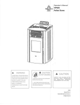
Harman PC 45 Corn/Pellet Stove
Label measures: 4.5"high x 11 7/8"wide
MINIMUM CLEARANCES
TO COMBUSTIBLES:
SIDEWALL TO STOVE 18" 12"
BACKWALL TO STOVE 2" 2"
CEILING TO STOVE TOP 20" 20"
STOVE CORNER TO DIAGONAL WALL 13" 9"
PREVENT HOUSE FIRES, OPERATE WITH VIEWING & ASH DOOR CLOSED.
UNIT MUST BE PLACE ON A NON-COMBUSTIBLE FLOOR PROTECTOR EX-
TENDING 6" TO THE FRONT, 6" TO SIDES AND 1" TO REAR.
EXHAUST TYPE: LISTED TYPE L OR PL VENT INSTALLED TO VENT MANU-
FACTURER'S INSTRUCTIONS AND LOCAL BUILDING CODES.
ELECTRICAL RATING: 6 AMPS, 120 VOLTS, 60 HERTZ
FUEL: PELLETIZED OR BIOMASS
INSTALL AND USE ONLY IN ACCORDANCE WITH MANUFACTURER'S INSTAL-
LATION AND OPERATING INSTRUCTIONS. CONTACT LOCAL BUILDING OR
FIRE OFFICIALS ABOUT RESTRICTIONS & INSTALLATION INSPECTION IN
YOUR AREA.
EPA EXEMPT PER 40 CFR 60.534, METHOD 28A.
APPROVED FOR USE IN MOBILE HOMES.
INPUT RATING: 0 TO 5.0 LBS PER HOUR.
DO NOT CONNECT THIS UNIT TO A CHIMNEY SERVING
ANOTHER APPLIANCE
LISTED CORN/PELLET FUEL BURNING ROOM HEATER
MODEL: PC 45
INSTALL WITH MINIMUM
CLEARANCES TO WALLS AS
SHOWN
TESTED TO : UL 1482
ASTM E1509
OREGON 814-23-900
ULC-S627
WH-PN 025
TEST DATE: MARCH 1998
CORNER INSTALLATION 9" WITH
OR 13" WITHOUT
SIDE SHIELDS
SIDEWALL-BACkWALL
INSTALLATION WITH
SIDE SHIELDS
2"
12"
2"
6"
6"
6"
1"
9-13"
9-13"
SIDEWALL-BACkWALL
INSTALLATION WITHOUT
SIDE SHIELDS
FLOOR PROTECTOR
MINIMUM SIzE
WITHOUT
SIDE SHIELDS
WITH
SIDE SHIELDS
18"
TAILLE MINIMALE
DE LA PROTECTION DE SOL.
INSTALLER AVEC LES DISTANCES
MINIMUM DE SECURITÉ COMME
INDIqUÉ.
INSTALLATION EN ANGLE 9" AVEC
OU 13" SANS PROTECTIONS
MURALES
DISTANCES AUX MURS
LATÉRAL ET ARRIÈRE AVEC
PROTECTIONS MURALES
2"
12"
18"
2"
6"
6"
6"
1"
DISTANCES AUX MURS
LATÉRAL ET ARRIÈRE SANS
PROTECTIONS MURALES
9-13"
9-13"
NE PAS CONNECTER CET APPAREIL À
UNE CHEMINÉE SERVANT UN AUTRE
APPAREIL.
ESPACES LIBRES MINIMUM
DES MATÉRIAUX COMBUSTIBLES:
DU MÛR DE CÔTÉ AU POÊLE 18" 12"
DU MÛR ARRIÈRE AU POÊLE 2" 2"
DU PLAFOND AU DESSUS DU POÊLE 20" 20"
DU COIN DU POÊLE AU MÛR DIAGONAL 13" 9"
PRÉVENIR LES FEUX DE MAISONS. OPÉRER SEULEMENT AVEC LA PORTE
D'OUVERTURE ET LA PORTE DES CENTRES FERMÉES. L'APPAREIL DOIT
ÊTRE PLACÉ SUR UN PLANCHER PROTECTEUR INCOMBUSTIBLE, CELUI-CI
S'ÉTENDANT DE 6" EN AVANT, DE 6" DES CÔTÉS ET D 1" DE L'ARRIÈRE.
SORTE D'ÉCHAPPEMENT: VENTILATEUR DE TYPE L OU PL INSTALLÉ SELON
LES INSTRUCTIONS DU FABRICANT ET SELON LES CODES LOCAUX DE
LA CONSTRUCTION.
PUISSANCE ÉLECTRIqUE: 6 AMPS, 120 VOLTES, 60 HERTZ
COMBUSTIBLE: DE BOULETTES COMBUSTIBLES OU BIOMASSES.
INSTALLER ET UTILISER SELON LES INSTRUCTIONS D'INSTALLATION ET
D'OPÉRATION DE FABRICANT. CONTACTER LE BUREAU DE LA CONSTRUC-
TION OU LE BUREAU DES POMPIERS AU SUJET DES RESTRICTIONS ET
DES INSPECTIONS D'INSTALLATION DANS VOTRE VOISINAGE.
EXEMPTION EPA PAR 40 CFR 60.534, DE MÉTHODE 28a
APPROUVÉ POUR L'USAGE DANS LES MAISONS MOBILES
PUISSANCE ESTIMÉE: 0 À 5.0 LBS PAR HEURE.
SANS LES
PROTECTEURS
DE CÔTÉ
AVEC LES
PROTECTEURS
DE CÔTÉ
WHI -
DO NOT REMOVE THIS LABEL.
NE PAS ENLEVER CETTE ÉTIQUETTE.
MANUFACTURED BY:
HARMAN STOVE COMPANY
352 MOUNTAIN HOUSE ROAD
HALIFAX, PA 17032
MADE IN USA
APPAREIL DE CHAUFFAGE CATALOGUÉ DE
MODÈLE POUR BRÛLER DES MAIS/BOULETTES COMBUSTIBLES.
MODÈLE: "PC 45"
C US
W/N 10941
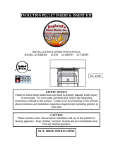
SAFETY NOTICE: IF THIS HARMAN STOVE IS NOT PROPERLY
INSTALLED. A HOUSE FIRE MAY RESULT. FOR YOUR SAFETY,
FOLLOW THE INSTALLATION DIRECTIONS. CONTACT LOCAL
BUILDING OR FIRE OFFICIALS ABOUT RESTRICTIONS AND
INSTALLATION INSPECTION REQUIREMENTS IN YOUR AREA.
Pl e a se co p y
yo u r
serial
number from
the label on your stove
to the box below.
The PC 45 Multi-fuel Stove makes burning corn, pellets, or grain more convenient than ever. It’s special Sidewinder
Burn Pot allows corn to be burned from three days up to a week without cleaning, depending on the corn’s moisture
level and burn rate.
Automatic Ignition allows you to ll the hopper, set your desired room temperature and walk away. The PC 45 will adjust
it’s feed rate based on the temperatures received by the room sensor, and keep your home at the set temperature.
The PC 45’s automatic temperature control system eliminates the warm/cold cycle associated with thermostatically
controlled heating systems and even turns the PC 45 on and off as needed.
Our exclusive Accordion Heat Exchanger and Air Cooled Combustion Blower allows the PC 45 to produce maximum
heat without creating high exhaust temperatures. The Outside Air option can increase heat efciency even more.
The PC 45 can burn corn or grain with moisture levels up to 16%, with 14.5% or less being ideal. It can also burn
pellets regardless of ash content. This allows you to buy lower cost fuel and still achieve the same results.
The label shown here is for reference only. See the unit label
for specic information regarding clearances and testing.

4 PC 45 Corn/Pellet Stove
Fig. 1
Fig. 2
Rear Cover
Panels
Shipping Bolts: These holes
are also used for Mobile Home
Installation
The PC 45 is bolted to the skid to prevent move-
ment during shipping.
To free the stove from the skid you must remove
the hold-down bolts in the rear of the pedestal
base.
To remove the rear cover panels, loosen the
screws slightly and slide the covers outward as
shown in gure 1. To reinstall, simply slide back into
place and retighten the screws.
Install the rebrick vertically on the angle above
the burnpot.

5
PC 45 Corn/Pellet Stove
Fig. 4
Fig. 5
18"
Fig. 3
Fig. 6: Refer to page
17 for detailed draft
settings and adjustment
procedures.
9"-13"
9"-13"
9" With Side Shields
13" Without Side Shields
When installing this unit in a mobile home several requirements must be
followed:
1. The unit must be bolted to the oor. This can be done with 1/4"
lag screws through the 2 holes in the base plate.
2. The unit must also be connected to outside air. See page 7.
3. Floor protection and clearances must be followed as shown.
4. Unit must be grounded to the metal frame of the mobile home.
5. Do not Install in a room designated for sleeping.
6. The structural integrity of the mobile home oor, walls, and ceiling/ roof
must be maintained.
Due to high temperatures, the stove should be placed out of trafc and away from
furniture and draperies.
Children and adults should be alerted to the hazards of high surface tem-
peratures and should stay away to avoid burn to skin and/or clothing.
Young children should be carefully supervised when they are in the same
room as the stove.
Clothing and other ammable materials should not be placed on or near
this unit.
Installation and repair of this Harman Stove should be done by a quali-
ed service person. The appliance should be inspected before use and at
least annually by a qualied service person. More frequent cleaning will be
required. It is imperative that control compartments, burners, and circulating
air passageways of the stove be kept clean.
Place the stove on a noncombustible oor or a oor protector; a
minimum of 3/8" material with .84 k value per inch. Floor protection
must extend 6 inches to the front, 6 inches to the sides and 1 inch
to the rear of the stove. Place the stove away from combustible
walls at least as far as shown in gures 3,4 & 5. Please note the
difference in side wall clearance with and without side shields.
Note that the clearances shown are minimum for safety but do
not leave much room for access when cleaning or servicing. Please
take this into account when placing the stove.
Connect the power cord to a 120 V.A.C. 60Hz grounded recep-
tacle. (A surge protector is recommened to protect the circuit board).
Prior to installing the ue pipe, connect a draft meter to the stove
as shown in g. 6. (The draft meter must have a minimum range of
0"- 0.5"). Turn stove to "TEST" Mode and record the draft reading
______. After the ue pipe is connected, check the draft reading
again making sure all doors and windows in the home are closed.
If this reading is more than.05" higher than the unconnected read-
ing, check for possible restrictions or the need for outside air. (See
page 7).

6 PC 45 Corn/Pellet Stove
WARNING: Venting terminals must not be recessed
into a wall or siding.
NOTE: Only PL vent pipe wall pass-throughs and
re stops should be used when venting through com-
bustible materials.
NOTE: Always take into consideration the effect
the prevailing wind direction or other wind currents
will cause with yash and /or smoke when placing the
termination.
A. The clearance above grade must be a minimum
of 18".
B. The clearance to a window or door that may be
opened must be a minimum of 48" to the side, 48" below
the window/door, and 12" above the window/door.
(
)
C. A 12" clearance to a permanently closed win-
dow is recommended to prevent condensation on
the window.
D. The vertical clearance to a ventilated soft located
above the terminal within a horizontal distance of 2 feet
(60 cm) from the center-line of the terminal must be a
minimum of 18".
E. The clearance to an unventilated soft must be
a minimum of 12".
F. The clearance to an outside corner is 11" from
center of pipe.
G. The clearance to an inside corner is 12".
H. A vent must not be installed within 3 feet (90 cm)
above a gas meter/regulator assembly when measured
from the horizontal center-line of the regulator.
I. The clearance to service regulator vent outlet must
be a minimum of 6 feet.
J. The clearance to a non-mechanical air supply inlet
to the building or the combustion air inlet to any other
appliance must be a minimum of 48”.
K. The clearance to a mechanical air supply inlet
must be a minimum of 10 feet.
()
L. The clearance above a paved sidewalk or a paved
driveway located on public property must be a minimum
of 7 feet.
M. The clearance under a veranda, porch, deck or
balcony must be a minimum of 12 inches.
NOTE: The clearance to vegetation and other exteri-
or combustibles such as mulch is 36” as measured from
the center of the outlet or cap. This 36” radius continues
to grade or a minimum of 7 feet below the outlet.
Certain Canadian and or Local codes or regulations
may require different clearances.
A vent shall not terminate directly above a side-
walk or paved driveway which is located between two
single family dwellings and serves both dwellings.
Only permitted if veranda, porch, deck, or balcony is
fully open on a minimum of 2 sides beneath the oor.
= Vent terminal

7
PC 45 Corn/Pellet Stove
Outside air ex pipe
goes here
Inlet Cover part#
1-10-08542
Flex pipe part#
1-00-08543
When installing in a house with a Heat Reclaiming
Ventilation System (HRV) be sure the system is bal-
anced and is not creating a negative pressure in the
house.
Outside air is optional except in mobile homes and
where building codes require. The benet of outside air
is mainly noticed in small very tight houses.
To install outside air use 2 3/8" I.D. ex pipe part num-
ber 1-00-08543. There is a break-away hole on the rear
panel which must be removed before connecting the ex
pipe. The pipe should be run outside and terminate 3
feet or more to the side or below the vent pipe outlet.
Never terminate the outside air above the vent pipe
outlet. The maximum length run of this pipe is 15 feet.
If a longer run is needed the size must be increased to
3". Inlet cover part number 1-10-08542 should be used
to keep birds, rodents etc. out of pipe.
Pellet venting pipe (also known as "PL" vent ) is
constructed of two layers with air space between the
layers. Some manufacturers produce PL vent designed
specically for corn-burning. If planning to burn corn or
other grains, be sure venting system is approved and
warranted for corn-burning. The sections of pipe lock
together to form an air tight seal, however, in some cases
a perfect seal is not achieved. For this reason and the
fact that the PC45 operates with a positive vent pres-
sure
Fig. 8
A combustion blower is used to extract the combus-
tion gases from the rebox. This causes a negative
pressure in the rebox and a positive pressure in the
venting system as shown in g. 7. The longer the vent
pipe and more elbows used in the system, the greater
the ow resistance. Because of these facts we recom-
mend using as few elbows as possible and 15 feet or
less of vent pipe. The maximum horizontal run should
not exceed 48". If more than 15 feet of pipe is needed,
the diameter should be increased from 3" to 4" because
a larger pipe creates less ow resistance.
+ = Positive static pressure
= Negative static pressure
Fig. 7
Pellet Vent Pipe or PL Vent Pipe Must be used.

8 PC 45 Corn/Pellet Stove
To reduce the probability of back-drafting or burn back
in the appliance during power failure conditions, the
appliance must be able to draft naturally, without opera-
tion of the combustion blower. Negative pressure in the
house may resist this natural draft if not accounted for
during the pellet stove installation.
Heat rises in the house, and leaks out at upper levels.
This air must be replaced with cold air from outdoors,
which ows into lower levels of the house. Vents and
chimneys into basements and lower levels of the house
can become the conduit for air supply, and reverse under
these conditions.
Per national building codes, consideration must be
given to combustion air supply to all combustion appli-
ances. Failure to supply adequate combustion air for
all appliance demands may lead to backdrafting of this
and other appliances.
When the appliance is side-wall vented;
The air intake is best located on the same exterior
wall as the exhaust vent outlet, and located lower
on the wall than the exhaust vent outlet.
When the appliance is roof vented;
The air intake is best located on the exterior wall
oriented toward the prevailing wind direction, dur-
ing the heating season.
The outside air connection will supply all of the de-
mands of the appliance. However, consideration must
be given to the total house demand. House demand may
consume the air needed for the stove. It may be neces-
sary to add additional ventillation to the space in which
the appliance is located. Consult with your local HVAC
professional to determine the ventillation demands for
your house.
To reduce the possibility of reverse drafting during a
power failure, Hearth & Home Technologies strongly
recommends:
● Installing the vent pipe with a minimum vertical rise
of ve feet, preferably terminating above the roof line.
● Installing outside air with the intake located below
the exhaust termination.
To prevent soot damage to exterior walls of the house,
and to prevent re-entry of smoke, soot, or ash into the
house:
● Maintain specied clearances to windows, doors,
and other air inlets, including air conditioners.
● Vents should not be placed below ventillated sof-
ts. Whenever possible, run the venting above the roof
line.
● Avoid terminating the vent in an alcove location.
● Vents should not terminate under overhangs, decks
or onto covered porches.
● Maintain a minimum clearance of 12" from the vent
termination to the exterior wall. If you see deposits devel-
oping on the wall, you may need to extend this distance
to accomodate your installation conditions.
Hearth & Home Technologies supplies an optional
battery back up system to operate the appliance dur-
ing a loss of electrical power. Whether you experience
frequent power failures or not, this back up system is
recommended.

9
PC 45 Corn/Pellet Stove
Fig. 9
This method provides excellent venting for normal
operation and allows the stove to be installed closest
to the wall. Two inches from the wall is safe; however,
four inches allows better access to remove the rear
panel. The vertical portion of the vent should be three
to ve feet high. This vertical section will help to provide
natural draft in the event of a power failure.
This method also provides excellent venting for normal
operation but requires the stove to be installed farther
from the wall. The vertical portion of the vent should be
three to ve feet high and at least three inches from a
combustible wall. This vertical section will help to pro-
vide natural draft in the event of a power failure.
If the stove is installed below grade the vent termina-
tion should be at least 1 foot above grade.
Fig. 10

10 PC 45 Corn/Pellet Stove
Fig. 11
Fig. 12
This method provides excellent venting for normal
operation. This method also provides natural draft in
the event of a power failure. If the chimney condition
is questionable you may want to install a liner as in
method #6. Check with your local regulations, some
municipalities require a complete liner.
This method provides excellent venting for normal
operation. This method also provides natural draft in
the event of a power failure.
The damper area must be sealed with a steel plate.
Kaowool, mineral wool or an equivalent non-combus-
tible insulation is recommended to be installed on top
of the sealing plate to reduce the possibility of con-
densation. The connector pipe should extend through
the smoke chamber to the base or into the rst ue
tile. A cap should be installed on the chimney to keep
out rain. If the chimney condition is questionable you
may want to install a liner all the way to the top as in
method #5. Check with your local regulations, some
municipalities require a complete liner.

11
PC 45 Corn/Pellet Stove
Fig. 13
This method provides excellent venting for normal
operation. This method also provides natural draft in
the event of a power failure.
In some places in the US and Canada, it is required
that the vent pipe extend all the way to the top of the
chimney. Check with your local codes.
In this method a cap should also be installed on the
chimney to keep out rain. Be sure to use approved pellet
vent pipe ttings. Seal pipe joints with silicone in addition
to the sealing system used by the manufacturer. Pipe
size should be increased to 4" using this method.
This method provides excellent venting for normal
operation. This method also provides natural draft in
the event of a power failure.
In some places in the US and Canada, it is required
that the vent pipe extend all the way to the top of the
chimney. Check with your local codes. The pipe or liner
inside the chimney should be 4"diameter.
In this method a cap should also be installed on the
chimney to keep out rain.
Fig. 14

12 PC 45 Corn/Pellet Stove
Fig. 15
It is recommended that outside
air be installed with this venting
conguration.
Fig. 16
Fig. 17
Through the ceiling vent, follow PL vent manufacturers
recommendations when using wall and ceiling pass
through.
18"

13
PC 45 Corn/Pellet Stove
The grain cap is designed to enhance the burn quality
of the fuel being burned (i.e. eld corn, wheat, barley,
rye, oats, etc.) Its purpose is to reect more heat
into the burn pot. This promotes a more thorough
burning of the fuel and less ash. Depending on the
quality of the fuel being burned, the effectiveness of
the grain cap may vary.
The grain cap will need to be removed for cleaning.
This part is classied as a consumable item and is
excluded from the product warranty.
1. Hook the slot on the grain cap over the lip on the
side rail of the burnpot, as shown.
2. Allow the grain cap to rest onto the burnpot
sides.
Grain Cap
Burn Pot
Fig. 18
The PC45 stove is built with a burn pot that has
.125 (1/8") combustion air holes. This grate has
no identifying marks.
Included with your stove is an additional grate
that has .0625 (1/16") combustion air holes.
This grate can be identied with etchings on the
bottom side. An ‘S’ is etched on one end and
‘724208’ is etched at the other end.
Depending on the type and the moisture
content, some corn or grain will burn better
with the smaller holes for combustion air, while
others may work better with the larger holes.
The PC45 is built with this burn
pot that has larger holes, Part #1-
10-724108.
Letter “S”
You may opt to change the
burn pot to this version with
smaller holes. This option has
the letter "S" marked on it & is
Part # 1-10-724208.

14 PC 45 Corn/Pellet Stove
For optimal performance burning wood pellets, the pellet kit #1-00-06801 is now
included. This kit allows you to convert the PC45 into a fully automatic pellet
stove with 50,000 BTU capacity, fast ignition and clean viewing glass. Due to the
fact that there are changes needed for the circuit board programing, it is recom-
mended that this installation be completed by a trained service technician. Be
sure the power cord is un-plugged prior to adjusting circuit board switches. The
pellet kit contains the instructions for the conversion, a new burn pot end gate,
and a new combustion blower inlet ring.
This gure shows the corn burn pot
as installed from the factory.
This gure shows the new end
gate which gets installed without
the stirring rod.
This gure shows the pellet burn
pot after installing the new end
gate.
The combustion blower inlet ring on the left is the one originally installed in the stove. Note the
larger opening in the ring on the right. This allows the PC45 to produce more heat when burning
pellets. The larger ring does the opposite when burning corn. If you want to switch back to corn or
grain, exchange the inlet ring back to the smaller opening.

15
PC 45 Corn/Pellet Stove
The PC45 corn/pellet stove is more than just automatic ignition, it is also automatic temperature
control. The automatic system will allow the re size to be adjusted to match the heating needs and
even put the re out if necessary. If heat is needed after the re is out, the PC 45 will automatically
re-ignite and adjust the re size to match the heating need. The totally automatic room sensor
mode is recommended because of its efciency. The unit can be switched between "AUTO" and
"MANUAL" at any time during operation.
Fig. 19:Room Temperature Mode: This setting will produce
a room temperature of 70 degrees with the distribution blower
at medium speed.
This setting will produce medium heat with the
distribution blower on "low".
Fig. 20: This setting will produce continuous maximum heat
output with the distribution blower at full speed.
In "Room Temp Mode" heat output is controlled automati-
cally by the Room Sensing Probe. When the Room Sensing
Probe calls for heat, the stove will increase output. When the
Room Sensing Probe is getting close to the set temperature,
the stove will begin to level off output and keep the re burning
at just the right temperature to maintain that setting.
High output is determined by the feed rate setting. This
setting, generally on #2 (corn) or #4 (pellet), can be increased
if higher burn rates are necessary.
When burning corn the feed rate setting can be adjusted
anywhere within the yellow range with a #3 setting being the
maximum setting, #1 the lowest setting. This setting will vary
depending on the quality of corn used.
When burning pellets the feed rate setting can be adjusted
within the full range between #1 on the low side to #6 on the
high side.
Overfeeding is not a safety concern, but the re may be
pushed off the burnpot and extinguish in the ash pan.
In "Room Temp Mode" a constant fuel consumption rate is
sacriced for exact room temperature. Therefore, as it gets
colder more fuel will be burned automatically.
The distribution blower speed will vary according to the
position of the mode selector pointer, and re size.
This allows for automatic ignition upon start-up only. The
unit can then be set at any desired setting. The heat output
and fuel consumption will remain constant regardless of
room temperature.
The unit's low burn or maintenance setting is as low as it
will go. It will not go out unless it runs out of fuel or is turned
off.
To kill the re or stop burning the stove, turn the Mode
Selector to "OFF". This will cause the re to diminish and
burn out. When the re burns out and the stove cools down
everything will s
top.
This insures
that all fuel in the burnpot and ashes located in the ash
pan are completely cold before shut down of the com-
bustion motor.
If you pull the plug to shut down the stove, all motors
will stop. This may cause incomplete combustion and smoke
in the rebox. If the load door is opened the smoke may
escape.
The best way to shut down the stove is to simply let it
run out of fuel, then the stove will shut down automatically.

16 PC 45 Corn/Pellet Stove
Make sure the unit is plugged into a 120 VAC, 60 HZ
electrical source. The power light should be the only
light lit. Anytime there is an interruption in power at the
receptacle, the combustion blower will run for 1 minute
after the power is restored. The control uses this time
to determine exhaust temperature and if there is a need
to remain on.
1.Turn the Mode Selector to "OFF"
2. Fill the hopper with corn or pellets.
3. Clean the burn pot and housing, if necessary.
4. If starting after an empty hopper, turn the feed
adjuster to "TEST" until the fuel is visible in the auger
tube opening. This also allows you to check the motors
for operation.
NOTE: The auger motor will not operate with the view
door or ash door open.
NOTE: The initial start-up on a new stove may require
the corn to be purged into the burnpot area before
continuing to step 5.
5. Turn the feed adjuster to #2 (corn) or #4 (pellet)
6. Flip the igniter switch up into the "AUTO" position.
7. Turn the temperature dial to the desired setting.
8. Turn the mode selector dial to Room Temperature or
Stove Temperature.
9. Fill the hopper with corn or pellets and remove the
ashes as required.
"NEVER USE GASOLINE, GASOLINE-TYPE LANTERN
FUEL, KEROSENE, CHARCOAL LIGHTER FLUID, OR
SIMILAR LIQUIDS TO START OR "FRESHEN UP " A
FIRE IN THIS HEATER. KEEP ALL SUCH LIQUIDS
WELL AWAY FROM THE HEATER WHILE IN USE".
Fig. 21

17
PC 45 Corn/Pellet Stove
The PC45 Corn/Pellet Stove is capable of manual operation. This also allows the opera-
tor to manually control operation during an emergency (i.e. igniter failure, when using some
types of auxiliary power.)
The unit can be switched between "AUTO" and "MANUAL" at any time during operation.
Fig. 22: Room Temperature Mode: This setting will produce a
room temperature of 70 degrees with the distribution blower at
medium speed.
Fig. 23: This setting will produce a large viewing re without a
distribution blower operating.
The re will have to be lit with starting gel and a
match, or started automatically, see "Automatic Opera-
tion". Turn to "Manual" position when the ignition cycle
has started.
The difference between "AUTO" Room Tempera-
ture Mode and "Manual" Room Temperature Mode is
that the re will not go out as the room temperature goes
above the control board setting. The unit can only go to
low burn and will remain there until it runs out of fuel or
until more heat is needed and the feed rate increases.
Feed rate adjustments and dial settings are the same
as "AUTO" settings.
The advantage of this mode is to allow the opera-
tor to have a large viewing re without blowing extra
heat into the room.
During operation, with the temperature dial set
at #4 or less, the distribution fan will not operate.
Therefore, there can be a higher burn rate (a larger
viewing re) without an excess of hot air blowing into
the room.
An example of when to use the Manual Stove
Temperature Mode is if you want to watch a large re
and the room is already up to temperature. The Stove
Temperature Mode allows you to have a larger re and
a lower sound level, without the distribution blower.

18 PC 45 Corn/Pellet Stove
Fig. 24
"NEVER USE GASOLINE, GASOLINE-TYPE LANTERN FUEL,
KEROSENE, CHARCOAL LIGHTER FLUID, OR SIMILAR
LIQUIDS TO START OR "FRESHEN UP " A FIRE IN THIS
HEATER. KEEP ALL SUCH LIQUIDS WELL AWAY FROM THE
HEATER WHILE IN USE".
Fig. 25
Fig. 26
To kill the re or stop burning the stove, turn the Mode
Selector to "OFF". This will cause the re to diminish and
burn out. When the re burns out and the stove cools down
everything will stop.
This insures
that all fuel in the burnpot and ashes located in the ash pan
are completely cold before shut down of the combustion
motor.
If you pull the plug to shut down the stove, all motors will
stop. This may cause incomplete combustion and smoke in the
rebox. If the load door is opened the smoke may escape.
The best way to shut down the stove is simply let it run out
of fuel, then the stove will shut down automatically.
Make sure the unit is plugged into a 120 VAC, 60 HZ
electrical source. The power light should be the only light
lit. Anytime there is interruption in power at the receptacle,
the combustion blower will run for 1 minute after the power
is regained.
1. Turn the Feed Adjuster to the desired feed rate,
approximately #2.
2. Turn the Mode Selector to "OFF" and then to the desired
mode. This will reset the control and start the combustion
motor.
3. Turn the Temperature Dial to the desired setting.
4. Clean the burnpot and housing, if necessary.
5. Fill the burnpot with corn up to the auger shaft. Then place
pellets on top of the corn as high as the shelf area. See corn
burnpot shown on left.
6. Add starting gel on top of the pellets, stir gel into the pellets
and corn for faster lighting.
7. Light the starting gel with a match and close the door.
Operation will begin when the fire reaches the proper
temperature.
8. Fill the hopper with corn and remove the ashes as
required.
1. Turn the Feed Adjuster to the desired feed rate,
approximately #4.
2. Turn the Mode Selector to "OFF" and then to the desired
mode. This will reset the control and start the combustion
motor.
3. Turn the Temperature Dial to the desired setting.
4. Clean the burnpot and housing, if necessary.
5. Fill the burnpot with pellets so that the auger tube opening
is covered and slopes away from the auger tube opening. See
pellet burnpot shown on left. If using corn burnpot setup, ll
to same level as corn above.
6. Add the starting gel on top of the pellets. Stir the gel into
the pellets for fast lighting.
7. Light the starting gel with a match and close the door.
Operation will begin when the fire reaches the proper
temperature.
8. Fill the hopper with pellets and remove the ashes as
required.

19
PC 45 Corn/Pellet Stove
Feed adjuster
Sets the maximum
feed rate.
Test
Runs all motors at full
speed for one minute
to che ck oper at i on .
Afterward the combustion
blower will go to minimum
and stay there.
Igniter switch
Set to appropriate Start-
Up mode.
Distribution Blower speed
adjustment range.
L = low
H = high
Variable speed anywhere
between L and H; although
as the stove temp. goes
up , so does the L and H
scale.
Temp dial
Allows you to adjust the room temperature in Room
Temp Mode using the outer scale marked in degrees
Fahrenheit. It also allows you to adjust the stove
temperature while in Stove Temp Mode using the inner
scale marked from 1 to 7.
Mode Selector
A l l o w s y o u t o c h o o s e
between Room Temp Mode,
Stove Temp Mode, or OFF.
Also allows you to vary the
distribution blower speed by
turning the knob to the high or
low side of each mode.
Power Light
Indicates power to the
control.
Indicates power to the
feed motor.
Indicates igniter is on.
Indicates power to
combustion blower.
Status Light
Will be lit in either stove
or room temp mode
when pointer is not
within off position band
except after normal shut
down. Blinks to indicate
errors listed below.
Indicates power to
distribution blower.
: Indicates that the control has calculated
poor or incomplete combustion occurring for more than
50 minutes. See Troubleshooting section for more de-
tails.
A six blink status may be set if the stove is allowed to
run out of pellets. To reset, turn mode selector to "OFF"
then back on to the desired mode. If the unit was not
out of pellets, see Troubleshooting section, Page 24,
for more details.
- Disconnect the power cord for a few
seconds and reconnect. If error still occurs call your
Harman Dealer.
Indicates that the ESP (Exhaust Sensing
Probe) has gone out of range too many times in a speci-
ed time. Perform a manual reset*, If the code returns
immediately, the ESP may be damaged or disconnected.
Otherwise, the exhaust system may need cleaned..
Can occur only in Room Temp Mode and
indicates Room Sensing Probe failed or not installed. If
a Room Sensing Probe is then installed, the status light
will automatically reset.
NOTE: Unit will not start in "AUTO" with this status er-
ror.
Indicates that
the unit has failed to light within the 45 minute start
cycle. To reset - Turn Mode Selector to "OFF", then turn
to either mode again.
Dealer Diagnostic Port
For dealer maintenance use
only. Requires special DDM
monitor supplied to Harman
Dealers exclusively.

20 PC 45 Corn/Pellet Stove
These units are pre-tested at the factory with exactly
120 Volts A.C., 60 Hz. They are checked and adjusted
for rebox tightness, gasket leakage, motor operation
and ignitor operation. The PC 45 is then factory set
at a mid-point adjustment and in most cases will not
need any adjustments.
The control board on the PC45 is equipped with
a low draft adjustment port. Located on the control
face just to the right of the igniter light. This voltage
adjustment is provided to allow the unit to be adjusted
for the household voltage where the unit is going to be
in permanent operation. NOTE: The line voltage varies
from area to area and often home to home.
The low draft voltage should be adjusted to achieve
the most efcient burn on low burn or "maintenance".
This voltage adjustment allows the installer to change
the low voltage set point approximately 10 volts. This
adjustment should be done by the installer during set
up because a draft meter reading is to insure
proper set up.
If the unit is not adjusted properly, it does not cause
a safety concern. If the unit is adjusted too high, only
efency is lost. If the unit is adjusted too low, the low
draft pressure switch will not allow the feeder motor or
the igniter to operate
.
A simple draft test should be performed after
completing the ue pipe installation. To record the results
for future reference:
Combustion Motor Speed Control
Low draft only set point.
The small straight screwdriver slot is plastic; therefore, the unit
can be adjusted while in operation.
Fig. 27
Fig. 28
1. Attach a draft meter capable of reading up to a
minimum of 0.5 inches of water column (W.C.).
2. Plug the unit's power cord into a 120VAC, 60 HZ
grounded outlet.
3. Close the hopper lid, front view door, and the ash
pan access door. Neither fuel or a re are required for
this test.
4. With the mode selector in the "OFF" position, turn the
feed adjuster to "TEST".
5. Record the high draft_____in W.C. (Normal is
-.35 to -.55) The control will be on the High Draft for a
minute.
6. After 1 minute is up, the combustion motor will go
down to low draft and the distribution blower will go on
high. Allow approximately 15 seconds to pass for the
combustion motor to slow before checking the low draft.
7. If the low draft is between -.25 and -.35, record the
reading _____ in W.C. If the reading is higher, slowly
turn the set screw counter-clockwise until the draft
lowers. If the reading is lower, very slowly turn the set
screw clockwise until the draft increases.
On a PC 45 the draft
hole is under the left
rear corner of the
rebox.
/