Page is loading ...

Instructions in English
SEALED PELLET STOVE
RAAM COMFORT AIR 8 S1
RAAM COMFORT AIR 8 UP! S1
PART 2 - OPERATION AND CLEANING
GBINSTALLATION GUIDE

II
TABLE OF CONTENTS
TABLE OF CONTENTS .................................................................................................. II
12FIRST IGNITION .....................................................................................................3
13CONTROL PANEL ....................................................................................................5
14MENU ITEMS AND OPERATION ................................................................................6
15SAFETY DEVICES ..................................................................................................16
16ALARMS ..............................................................................................................17
17RECOMMENDATIONS FOR SAFE USE .......................................................................22
18CLEANING ...........................................................................................................23
19TROUBLESHOOTING .............................................................................................32
20CIRCUIT BOARD ...................................................................................................35

1
3
3
12-FIRST IGNITION
Technical Dept. - All rights reserved - Reproduction prohibited
WARNINGS BEFORE IGNITION
GENERAL WARNINGS
Remove any objects that may burn from the product and from the glass(manual, various adhesive labels or any polystyrene).
Check that the brazier is positioned correctly and rests properly on the base.
The rst ignition may not be successful as the feed screw is empty and does not always manage to load the brazier
with the required amount of pellets in time to light the ame.
CANCEL THE FAILED IGNITION ALARM BY PRESSING AND HOLDING THE ON/OFF KEY FOR A FEW SECONDS. REMOVE THE
PELLETS LEFT IN THE BRAZIER AND REPEAT THE IGNITION.
SETTINGS TO BE CARRIED OUT BEFORE THE INITIAL START-UP
After connecting the power cable to the back of the product, turn the switch at the back to position (I). To switch the stove on and o,
press1 on the control panel or press 3 from the remote control (optional accessory).
The display on the panel will be ON with a ashing ame. When the ame stops blinking, the stove has reached the operating condition
to “supply power”.
The default factory set room temperature is 20°C. To change this setting, follow the instructions in the adjustments menu. Do the same
to set the heating water temperature and the speed of the room fan (if required). To activate an external thermostat, if present, see the
dedicated paragraph.
SWITCHING THE EQUIPMENT OFF
To switch the equipment o, press and hold the ON-OFF button on the remote control or on the APP. The acoustic beep conrms this phase
has started.
Alternatively, switch it o from the emergency panel by following the instructions provided in the dedicated chapter
The equipment will start the shutdown process which involves consuming the residual pellets in the brazier, the latter being cleaned and
the residual heat in the structure being disposed of.

4
12-FIRST IGNITION
During the disposal phase of the residual heat, the fans operate at about 80% of their output and the speed cannot be varied. This is
determined by the need for all the accumulated heat to be evacuated safely and quickly. The switch-o phase can last 15 - 30 minutes
depending on the heat stored in the structure, determined by the duration and the operating regime of the product throughout the day.
When the internal temperature drops below the set thresholds, the fans for hot air and exhaust fume extraction will automatically switch
o.
POWER SUPPLY
When ignition is complete, the panel will display ON with a steady ame at level 3 . The following ame modulation for higher or
lower power is then controlled autonomously based on reaching the set temperature.
(see also “OPERATING MODE” - “Set Flame”).
If the ame fails to ignite, despite a regular ow of pellets, check that the brazier is seated correctly: it must rest snugly against the
interlocking slot and be clean of any ash incrustations. If no anomaly is found during this inspection, there may be a problem with
the product components or installation may not be correct.
REMOVE THE PELLETS FROM THE BRAZIER AND CONTACT AN AUTHORISED TECHNICIAN.
Please ensure the brazier is clear of ALL pellets and ash build up following any failed ignitions. Failure to clear out
the brazier prior to resetting may result in further failed ignitions or explosive ignition under certain conditions.
It is good practice to ensure eective ventilation in the room during the initial ignition, as the product will emit some
smoke and smell of paint.
Do not stand close to the product and ventilate the room as mentioned. The smell of paint will disappear after about an hour of operation,
however, it is not harmful in any case.
The product will be subject to expansion and contraction during the ignition and cooling stages, therefore slight creaking noises may be
heard.
This is absolutely normal as the structure is made of laminated steel and must not be considered a defect.
DO NOT EXPECT HEATING EFFICIENCY IMMEDIATELY!!! THE PRODUCT NEEDS SOME RUNNING-IN TIME.
It is extremely important to make sure the product does not reach high temperatures straight away, but to increase the temperature
gradually using low power at rst.
This will prevent damage to the welds and to the steel structure.
Do not touch the product during the rst lighting, as it is during this stage that the paint sets. If you touch the paint,
you may expose the steel surface.
If required, touch up the paint with the spray can of the specic colour.

7
2 3 4
61 5
5
13-CONTROL PANEL
Technical Dept. - All rights reserved - Reproduction prohibited
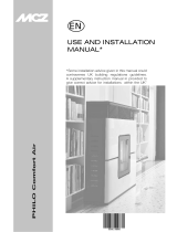
KEY
1. Stove start-up/shutdown
2. Scrolling down through the programming menu.
3. Menu
4. Scrolling up the programming menu.
5. Decreases set temperature / programming functions.
6. Increases set temperature / programming functions.
7. Display.

6
14-MENU ITEMS AND OPERATION
MAIN MENU
Press key 3 (menu) to access it. The options accessed are:
• Date and Time
• Timer
• Sleep (only when stove is on)
• Settings
• Info
Date and time conguration
Proceed as follows to congure the date and time:
• Press the “menu” key.
• Select “Date and Time”.
• Press “menu” to conrm.
• Scroll through with the arrow keys and select the variables to be edited one at a time: Day, Hour, Min, Num. day, Month, Year.
• Press “menu” to conrm
• Use the + and - keys to edit.
• Lastly, press “menu” to conrm and “esc” to exit.
CONFIGURATION OF PROGRAMMED MODE (TIMER) - Main menu
The current time and date must be congured to ensure correct operation of the timer.
There are six congurable TIMERS. For each one, the user can select a start-up and shutdown time and the days of the week when it is in
use.
When one or more programs are active, the status of the stove and the TIMER “n” alternate on the display, “n” is the number of timer
programs in use, separated by dashes
Example:
TIMER 1 Timer 1 program active.
TIMER 1-4 Timer 1 and 4 programs active.
TIMER 1-2-3-4-5-6 All timer programs active.
EXAMPLE OF PROGRAMMING
With the stove on or o:
• access the MENU,
• scroll to the TIMER item by using the <> arrows,
• press the “Menu” key
• the system shows “P1” (Press the <> keys to move through the timers P2, P3, P4, P5, P6)
• Press the “Menu” key to activate “P1”
• press + - and select “ON”
• press the “Menu” key to conrm
At this point the start time is 00:00. Press the + - key to set the start time and press the “menu” key to conrm.
Next, the proposed shutdown time is 10 minutes later than the congured start time: press the + key and edit the shutdown time, and
press the “menu” key to conrm.
Next, you are asked to set the days of the week when the congured timer is to be enabled or disabled. Press the - or + keys to select the
day you want to activate the time. It will light up white, then conrm with the “menu” key. If no day of the week is selected for enabling
the timer, the timer program is no longer enabled on the status screen.
Next, program the other days or press “ESC” to exit. Repeat this procedure to program the other timers.

7
14-MENU ITEMS AND OPERATION
Technical Dept. - All rights reserved - Reproduction prohibited
EXAMPLES OF PROGRAMMING
P1 P2
on o day on o day
08:00 12:00 mon 11:00 14:00 mon
Stove on between 08:00 and 14:00
P1 P2
on o day on o day
08:00 11:00 mon 11:00 14:00 mon
Stove on between 08:00 and 14:00
P1 P2
on o day on o day
17:00 24:00 mon 00:00 06:00 tue
Stove on between 17:00 on Monday to 06:00 on Tuesday
NOTES ON USE OF THE TIMER
• The timer start always occurs with the last temperature and ventilation settings (or with the default settings at 20°C and V3 if they
have never been altered).
• The start-up time goes from 00:00 to 23:50
• If the shutdown time has not yet been saved, the program proposes a start-up time at +10 minutes.
• A timer program turns o the stove at 24:00 on one day and another program starts it up at 00:00 on the next day: the stove
remainson.
• A program proposes a start-up and/or shutdown time that overlap the times of another program: if the stove is already on, the start
has no eect while OFF turns o the stove.
• When the stove is on and the timer is active, pressing the OFF key turns o the stove. The stove then restarts automatically at the
next time of the timer.
• When the stove is o and the timer is active, pressing the ON key turns on the stove. The stove then stops automatically at the next
time of the timer.
SLEEP FUNCTION (main menu)
Sleep mode may only be activated when the stove is on and allows you to quickly set a time for the product to turn o.
To set the Sleep function, proceed as follows:
• Enter the MENU
• Scroll to the SLEEP item with the <> arrows
• Press Menu
• Set the desired shutdown time by using the + and - keys.
The panel shows a shutdown time of 10 minutes after the current time, which can be adjusted with key 6 up to the following day (i.e. the
shutdown can be delayed up to a maximum of 23 hours and 50 minutes).
If the SLEEP function is active with the TIMER active, the former has priority, therefore the stove will not turn o at the time set in the timer
program but at the time set by the sleep function, even if it comes after the time set by the timer.

P5 P1
8
14-MENU ITEMS AND OPERATION
OPERATING MODE
ADJUSTMENT MENU
“Adjustments” menu settings determine the operating mode of the stove.
To access the menu, proceed as follows:
• Press the + - keys
• Scroll by using the <> arrows and select “Set Amb. T” or “Set Ventilation T” or “Set Flame”
• Press “menu” to enter the option selected.
• Change by using the + - keys.
• Press “menu” to conrm and “esc” to exit.
Set Amb T - this function is used to set the temperature to be reached in the room in which the stove is installed, from a minimum of 5°C
to a maximum of 35°C. When this condition is met, the stove setting is equivalent to the minimum consumption values (the ame and hot
air fan speed at minimum), and then returns to the set values when the room temperature drops below the set threshold.
N.B: The point to the right of the room temperature on the control panel display indicates the half degrees (e.g. 23.°C is equivalent to
23.5°C).
Set Vent - this function allows you to select the desired speed of the room fan from 1 to 5.
Set Flame - this function allows you to set the power of the ame from a minimum of 1 to a maximum of 5. The power levels correspond
to a dierent value of fuel consumption, setting 5 heats the room in less time and setting 1 can keep the room temperature stable for a
longer period of time. The set ame is automatically set to a minimum when the set temperature value is reached.
DISPLAY WITH STOVE ON
if the bars are all full, the stove is on ame power 5
if only one bar is full, the stove is on ame power 1
if the bars are ashing, automatic cleaning is in progress

9
14-MENU ITEMS AND OPERATION
Technical Dept. - All rights reserved - Reproduction prohibited
SETTINGS MENU
The SETTINGS menu enables to congure the stove operating modes:
a. Language.
b. Cleaning (only displayed when stove is o).
c. Feed screw loading (shown only when stove is o).
d. Tones.
e. External thermostat (activation).
f. Auto Eco (activation).
g. Eco Turn-o T (default 10 minutes).
h. Pellet recipe.
i. Smoke rpm % var.
j. Components test (only displayed when the stove is o).
k. “Chimney sweeper” function (can only be enabled when stove is on, to check emissions in eld).
l. Technical menu.
a - Language
Proceed as follows to select the language:
• Press the “menu” key.
• Use the arrow keys to scroll through and select “Settings”
• Press “menu” to conrm.
• Use the arrow keys to scroll through and select “language”.
• Press “menu” to conrm.
• Use the + - keys to select the required language (IT/EN/DE/FR/ES/NL/PL/DK/SLO)
• Press “menu” to conrm and “esc” to exit.
b - Cleaning
Proceed as follows to select “Cleaning” (only with stove o):
• Press the “menu” key.
• Use the arrow keys to scroll through and select “Settings”
• Press “menu” to conrm.
• Use the arrow keys to scroll through and select ‘’Cleaning’’
• Press “menu” to conrm.
• Use the + - keys to select “On”.
• Press “esc” to exit.
c - Feed screw loading
To select ‘’Feed screw loading’’ (only with stove o), proceed as follows:
• Press the “menu” key.
• Use the arrow keys to scroll through and select “Settings”
• Press “menu” to conrm.
• Scroll with the arrows and select “Feed screw loading”.
• Press “menu” to conrm.
• With the + key “Enable” feed screw loading.
• Press “esc” to exit.

10
14-MENU ITEMS AND OPERATION
d - Tones
This function is disabled by default. To enable it proceed as follows:
• Press the “menu” key.
• Use the arrow keys to scroll through and select “Settings”
• Press “menu” to conrm.
• Use the arrow keys to scroll through and select ‘’Tones’’
• Press “menu” to conrm.
• Using the + - keys, select “On/O”.
• Press “menu” to conrm and “esc” to exit.
e - External thermostat (see dedicated chapter)
f - Auto-Eco activation (see dedicated chapter)
To select the Auto-Eco function, proceed as follows:
• Press the “menu” key.
• Use the arrow keys to scroll through and select “Settings”
• Press “menu” to conrm.
• Scroll by using the arrows and select “Auto-Eco”.
• Press “menu” to conrm.
• Use the + - keys to select “On”.
• Press “menu” to conrm and “esc” to exit.
g - Eco stop t (see dedicated chapter)
To select the Eco stop t function, proceed as follows:
• Press the “menu” key.
• Use the arrow keys to scroll through and select “Settings”
• Press “menu” to conrm.
• Scroll with the arrows and select ‘’Eco stop t.
• Press “menu” to conrm.
• With the + - keys, insert the minutes (from 1 to 30’).
• Press “menu” to conrm and “esc” to exit.
AUTO ECO MODE (see activation and shutdown paragraph above)
For activation of the “Auto Eco” mode and time adjustment, see paragraphs 8 f and 8 g respectively.
The option ‘’ECO stop t” can be adjusted to ensure correct operation in the various environments in which the stove can be installed and to
avoid constant shut-downs and start-ups when the room temperature is subject to sudden change (drafts, poorly insulated rooms, etc.).
The ECO shutdown procedure is activated automatically when the power recall device is satised (room probe +1°C or external thermostat
with an open contact), the “ECO stop t starts to decrease the time (factory default 5 minutes, which can be changed from the “Settings”
menu). During this stage, the panel alternates between displaying ON with a small ame and Timer (if active) - Eco active. The minutes
counting down to Eco Stop are shown at the top of the display. The ame moves to P1 and remains there until the set “”ECO stop T” time
reaches zero, and if the conditions are still met, goes to the shutdown stage. The ECO stop count is cancelled if one of the devices recalls
power.
When the boiler begins to turn o, the panel displays: O - Eco Active - ashing small ame.
When the stove turns o, OFF-ECO appears on the display with the ame symbol o.
The following conditions have to be met simultaneously for ECO to restart:
• room probe -1°C or external thermostat with a closed contact (for at least 20” in order to prevent false recalls)
• 5 minutes have passed since shutdown.

11
14-MENU ITEMS AND OPERATION
Technical Dept. - All rights reserved - Reproduction prohibited
h - Pellet Recipe
This function is for adapting the stove to the type of pellet in use. As there are many types of pellets available on the market, operation
of the stove can vary considerably according to the quality of the fuel. When the pellets clog up the brazier due to excess loading of fuel
or when the ame is always high even at low power, or when the ame is low, it is possible to decrease/increase the amount of pellets
in the brazier:
The available values are:
-3 = A decrease of 20% with respect to the factory setting.
-2 = A decrease of 13% with respect to the factory setting.
-1 = A decrease of 6% with respect to the factory setting.
0% No changes.
3 = An increase of 10% with respect to the factory setting.
2 = An increase of 6% with respect to the factory setting.
1 = An increase of 3% with respect to the factory setting.
Proceed as follows to edit the recipe:
• Press the “menu” key.
• Use the arrow keys to scroll through and select “Settings”
• Press “menu” to conrm.
• Scroll with the arrows and select “Pellet recipe’’
• Press “menu” to conrm.
• Edit the % by using the + - keys.
• Press ‘’menu’’ to conrm and ‘’esc’’ to exit.
i - Smoke rpm % variation
In the event the installation presents problems in extracting smoke (lack of draught or even pressure in the duct), it is possible to increase
the smoke and ash extraction speed. This change resolves all potential problems related to pellets clogged in the brazier and deposits
forming at the bottom of the brazier itself caused by poor quality fuel or fuel that produces a lot of ash. The values available range from
-30% to +50%, with increments of 10 percent at a time. Negative variation may be required if the ame is too low.
To edit this parameter, proceed as follows:
• Press the “menu” key.
• Use the arrow keys to scroll through and select “Settings”
• Press “menu” to conrm.
• Scroll with the arrows and select “Fume rpm Var.”
• Press “menu” to conrm.
• Edit the % by using the + - keys.
• Press ‘’menu’’ to conrm and ‘’esc’’ to exit.
j - Components test
This can only be done when the stove is o and allows you to select the components to be tested:
• Glow plug: it is turned on for a xed period of 1 minute during which the panel displays the countdown in seconds.
• Feed screw: it is powered for a xed period of 1 minute during which the panel displays the countdown in seconds.
• Extractor: it is activated at 2500 rpm for a xed period of 1 minute during which the panel displays the countdown in seconds.
• Heat exchanger: enables you to conduct the test in V5 for a xed period of 1 minute during which the panel displays the countdown
in seconds.
Proceed as follows to enable the “Components test” function (only with stove o):
• Press the “menu” key.
• Use the arrow keys to scroll through and select “Settings”
• Press “menu” to conrm.

12
14-MENU ITEMS AND OPERATION
• Use the arrow keys to scroll through and select ‘’Components test’’
• Press “menu” to conrm.
• Use the + - keys to select the test to be carried out.
• Press ‘’menu’’ to conrm and ‘’esc’’ to exit.
k - Chimney sweeper function (for maintenance operators only) -
This function can only be activated when the stove is on and power is supplied, and it forces heating operation at parameters P5, with fan
(if present) in V5. Any corrections to the loading/smoke ventilation percentage must be read. This state lasts 20 minutes, the countdown
is displayed on the panel.
The technician can stop this stage at any moment by quickly pressing the on/o key.
Enable the “Chimney sweeper” function as follows:
• Press the “menu” key.
• Use the arrow keys to scroll through and select “Settings”
• Press “menu” to conrm.
• Use the arrow keys to scroll through and select ‘’Chimney sweeper function’’
• Press “menu” to conrm.
• Use the + - keys to select “On” (O by default)
• Press ‘’menu’’ to conrm and ‘’esc’’ to exit.
l - Technical menu
To access the technical menu, you must contact the service centre as it requires a password.
Proceed as follows to access the “technical menu”:
• Press the “menu” key.
• Use the arrow keys to scroll through and select “Settings”
• Press “menu” to conrm.
• Use the arrow keys to scroll through and select ‘’Technical menu’’
• Press “menu” to conrm.
• With the + - keys, select “Product Type”, “Service”, “Counter memories”, “Parameters”.
• Press ‘’menu’’ to conrm and ‘’esc’’ to exit.
INFO MENU
• Product type
• Firmware version
• Software info
• Total hours
• No. of start-ups
• Extractor rpm
• Smoke T.
• Heat exchanger voltage
• Feed screw loading
• Flame

13
14-MENU ITEMS AND OPERATION
Technical Dept. - All rights reserved - Reproduction prohibited
EXTERNAL THERMOSTAT CONNECTION (optional)
The room thermostat is not included with the stove and must be installed by a qualied technician.
ATTENTION!
The electrical wires must not come into contact with the hot parts of the stove.
The temperature of the stove can also be controlled by an external room thermostat. It must be positioned centrally in the room where
the stove is installed. It provides a closer match between the heating temperature required to the stove and the actual room temperature
it provides.
Connect the cables coming from the external thermostat to terminal 14 on the board on the stove.
Proceed as follows to enable the external thermostat (factory settings OFF):
• Press the “menu” key.
• Scroll with the arrows to “Settings”.
• Press “menu” to select.
• Now use the arrows to scroll to “External thermostat”.
• Press “menu” to select.
• Press the - + keys.
• Select “On” to activate the external thermostat.
• Press the “menu” key to conrm.
• Press the “esc” key to exit.
Once the external thermostat has been enabled, instead of displaying the detected temperature from the probe on the stove, ON or OFF
will appear, depending on whether you have requested heat from the external thermostat or not.
ON if the external thermostat contact is closed, OFF if the contact is open.

6
5
4
1
2
3
14
14-MENU ITEMS AND OPERATION
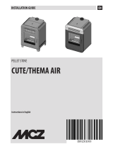
Remote control (accessory - NOT SUPPLIED)
LEGEND OF BUTTONS
1. Increase temperature set-point 4. Temperature/power switch and vice versa.
2.Decrease temperature set-point 5/6. Set power and ventilation
3. ON/OFF
PLEASE NOTE Adjusting the temperature with the remote control has no eect if the external thermostat has been selected.
Attention! Before using, remove the protection from the battery. The batteries are not included.
Keys 1 and 2: set the room temperature (automatic mode). See paragraph “Automatic mode”.
Keys 6 and 5: set power and ventilation (manual mode). The values that can be set are from 1 to 5.
Power does not scale immediately but reaches it at the set time (1 power per minute)
Button 3: On/O
Button 4: moves on from temperature to ame power; when passing from one status to another, the following values will be set:
- Temperature 23°C.
- Power 3 ventilation 3

15
14-MENU ITEMS AND OPERATION
Technical Dept. - All rights reserved - Reproduction prohibited
Batteries - type and replacement
The batteries are in the bottom of the remote control. To replace them, pull out the battery holder and remove or insert the battery in the
orientation marked on the remote control and on the battery itself.
The remote control takes 1 CR2025 lithium battery.
Used batteries contain metals which are harmful to the environment, so they must be disposed of separately in
appropriate containers.
If the remote control is o because it has no battery, the stove can be controlled with its top-mounted control panel.
While replacing the battery, observe the orientation marked inside the battery compartment.

16
15-SAFETY DEVICES
SAFETY DEVICES
The product is tted with the following safety devices
PRESSURE SWITCH
Monitors pressure in the smoke duct. It is designed to shut down the pellet feed screw in the event of an obstructed ue or signicant
back-pressure (from wind).
SMOKE TEMPERATURE PROBE
Detects the temperature of the smoke, thereby enabling start-up or stopping the product when the temperature drops below the preset
value.
CONTACT THERMOSTAT IN THE FUEL TANK
If the temperature exceeds the preset safety level, it immediately shuts down the stove.
ELECTRICAL SAFETY
The stove is protected against violent changes in current by a general fuse located in the control panel at the back of the stove. Other fuses
that protect the circuit boards are located on the latter.
SMOKE FAN
If the fan stops, the circuit board immediately shuts o the supply of pellets and an alarm message is displayed.
GEAR MOTOR
If the gear motor stops, the stove will continue to run until the ame goes out due to lack of fuel and until a minimum level of cooling is
reached.
TEMPORARY POWER OUTAGE
When a power outage lasts less than 10’’ the stove returns to its previous operating state. If it is longer, it executes a cooling/re-ignition
cycle.
FAILED IGNITION
If during ignition no ame develops, the stove will go into alarm condition.
TAMPERING WITH THE SAFETY DEVICES IS PROHIBITED
If the product is NOT used as described in this instruction manual, the manufacturer declines all liability for any
damage caused to persons and property. The manufacturer furthermore denies any liability for damage to persons
and property arising from failure to observe all the rules contained in the manual and specically:
• All the necessary measures and/or precautions must be adopted when performing maintenance, cleaning and
repairs.
• Do not tamper with the safety devices.
• Do not remove the safety devices.
• Connect the product to an ecient smoke expulsion system.
• First, check that the environment where it is to be installed is properly ventilated.
Only after having removed the cause that triggered the safety system is it possible to start the product again and
therefore restore automatic operation of the probe. This manual will help you understand which anomaly has
occurred, and explain how to operate according to the alarm message displayed on the appliance.

17
16-ALARMS
Technical Dept. - All rights reserved - Reproduction prohibited
ALARM SIGNALLING
When an operating condition other than the one expected for regular stove operation occurs, an alarm is triggered.
The reason for the alarm is shown on the control panel. The sound signal is not enabled for alarms A01-A02 in order not to disturb the user
when there is an absence of pellets in the hopper during the night.
Panel signalling Type of problem Solution
A01
The ame does not light Check the level of pellets in the hopper.
Check that the brazier is correctly positioned in its seat
and has no deposits or unburnt material.
Make sure the glow plug warms up.
Thoroughly empty and clean the brazier before
restarting.
A02
The re goes out abnormally. Check the level of pellets in the tank.
A03
Thermostat alarm
The temperature of the pellet hopper exceeds
the required safety threshold.
Wait until the end of the cooling stage, stop the alarm
and re-ignite the stove setting the supply of fuel to
minimum (SETTINGS menu - Pellet recipe). If the
alarm persists, contact the service centre.
Check whether the room fan is working correctly.
A04
Smoke overtemperature. Reduce the load of pellets (SETTINGS menu - Pellet
recipe). Check cleaning of the brazier.
A05
Safety devices alarm
Smoke pressure switch triggered Check for chimney obstructions / door open
Fuel loading hatch Close the hatch.
Lower the fuel level in the hopper.
Open stove door Close the door
A08
Anomalous operation of smoke fan. Cancel the alarm and turn the stove on again. If the
alarm persists, contact the service centre.
A09
Smoke sensor fault. Cancel the alarm and turn the stove on again. If the
alarm persists, contact the service centre.
Service
Routine maintenance warning (does not seize) When this blinking message appears upon start-up,
it means that the operating hours preset before
maintenance have expired. Call the service centre.
ALARM RESET
To reset the alarm, press and hold key 1 (ESC) for a few seconds. The stove checks whether or not the cause of the alarm is ongoing.
In the rst case, the alarm continues to be displayed, in the second case it turns OFF.
If the alarm persists, contact a service centre.

18
16-ALARMS
NORMAL SHUTDOWN (on the panel: OFF with ashing ame)
When the shutdown key is pressed, or when there is an alarm signal, the stove enters the thermal extinguishing stage which involves
automatic execution of the following stages:
• Pellet loading stop
• The room fan maintains the set speed until reaching the shutdown temperature
• The smoke extractor fan is activated at maximum speed and remains on for a xed period of 10 minutes, at the end of which if the
smoke T has dropped below the shutdown threshold, the fan stops, otherwise it will continue to operate at minimum speed until the
temperature drops below the threshold and then turn o.
• If the stove has been shut down regularly but, due to thermal inertia, the smoke temperature exceeds the threshold again,
theshutdown stage will be repeated at minimum speed until the temperature drops.
BLACKOUT WITH STOVE ON
In the event of a blackout, the stove acts as follows:
• Blackout less than 10”: resumes operation;
• After a power outage of more than 10’’ which occurred when the stove was on, or during ignition, when the stove is powered again
it returns to its previous operating condition as follows:
1. Cools the boiler by activating the smoke extractor at minimum speed for 10’ then proceeds to the next step;
2. Restores the stove to the operating condition prior to the blackout.
During stage 1, the panel shows ON BLACK OUT.
During stage 2, the panel shows Ignition.
If during stage 1 the stove receives manual user commands from the control panel, it stops the blackout reset sequence and begins the
start-up or shutdown as requested by the user.
BLACKOUT OF MORE THAN 10’’ DURING STOVE SHUTDOWN
If the stove experiences a loss of power LONGER THAN 10” while it is shutting down, when power is restored to the stove, it will
automatically turn on in shutdown mode, even if the smoke temperature has fallen below 45°C in the meantime. This last stage can be
skipped by pressing key 1 (esc) (skips to start-up) and pressing it again (recognises that the stove is o).
BLACKOUT OF MORE THAN 10’’ WITH THE STOVE OFF FOR ECOSTOP
Once power has been restored, a 5-minute timer is set as though the stove were in shutdown mode. Should there be a request for heat in
these 5 minutes, the stove will not start.
SAFETY DEVICES ALARM A05
The safety devices alarm includes operation of the smoke pressure switch, of the fuel loading hatch and of the open stove door.
The alarm will be triggered after 30 seconds, after which the stove will stop working (e.g. after 30 seconds with the pellet loading
hatch open, alarm A05 will be triggered).

19
16-ALARMS
Technical Dept. - All rights reserved - Reproduction prohibited
In the event that alarm A05 is triggered often, please note that:
A05
Safety devices alarm
Smoke pressure switch triggered Check for chimney obstructions / door open
Fuel loading hatch Close the hatch.
Lower the fuel level in the hopper.
Open stove door Close the door
it is required to check some points to verify the cause of the problem and potentially operate on some adjustments and/or safety devices
to restore correct operation of the product.
However please note that all adjustments and alterations aecting the operational safety devices, must only be performed if THE
PRODUCT IS INSTALLED IN COMPLIANCE WITH THE STANDARDS AND LAWS IN FORCE AND IF IT IS SERVICED PROPERLY BY AUTHORISED AND
SPECIALISED PERSONNEL. Alterations performed randomly, to ensure operation of the product even under non-compliant conditions, can
cause serious damage to property and injuries to people.
Attention!
The adjustments must only be carried out by authorised and qualied personnel under their responsibility and
by checking the conformity of the installation beforehand. The manufacturer declines all liability for damage to
property or injuries to people in the event of altering the safety devices.
All liability for improper use of the product is entirely borne by the user and relieves the Manufacturer from any civil
and criminal liability.
Series of stoves equipped with a pressure switch installed on the hopper with the sampling point positioned on the bottom, to the right of
the gear motor. This system protects the whole system ensuring tightness of the stove throughout its duration.
It is important to understand that the pressure switch can be triggered with each signicant drop in negative pressure and may be due to:
• Flue clogging.
• The presence of a foreign body in the ue (birds, nests, clogged grates, etc.).
• Wind coming through the ue because it is unprotected or the installation was wall-mounted or required no ue.
• Cold air draught down the ue.
• A damaged pressure switch.
• Blocked membrane inside the pressure switch because soot or pellet dust ltrated.
• The pellet hopper is open or ajar for more than 60 seconds (60 seconds is the estimated time to reload the hopper).
• Pellet trapped between the hopper cover and the hopper, which prevents the gasket to seal.
• Broken/worn hopper cover gasket.
• The gasket between the feed screw and the boiler is damaged or positioned incorrectly.
• Fire door is open or the gasket is worn.
• Clogged lateral smoke exchangers.
• Inspection caps with gaskets installed incorrectly after maintenance.
• Feed screw clogged by compressed pellets at the top.
• The installation is compliant and the ue/smoke tting does not generate obvious obstructions which can stop the release of smoke,
such as: long horizontal sections (over 3 metres), uninsulated smoke ducts, “wall-mounted” smoke exhaust without proper terminals
(installation regulated and permitted in France only [ZONE 3])
• Internal air extraction or recirculation systems (e.g. VMC systems) that generate internal negative pressure exceeding that required
by law (not exceeding 4 Pa)
• Installed without combustion air ducting, it is crucial to check that there is an ecient air inlet dedicated to the stove, according to
the specications referred to in chapter 2 of this manual.
The circuit board has also been equipped with an automatic device with a timer and contactors which increase the RPM of the smoke
extractor so as to restore the negative pressure inside the hopper and therefore the pressure switch, if the cover is opened for top-up or
if there is an immediate or occasional pressure drop such as gusts of wind outside. If the pressure drop lasts for more than 60 seconds,
theproduct is set in an alarm status (A05 or A18)

20
16-ALARMS
Remembering that the draught recommended for the products to work properly is 10 Pa at maximum capacity and 5 Pa at minimum
(according to the technical data sheet found in the user and maintenance manual), adjustments may be required in worse draught
conditions (also due to the position of the ue in areas that are particularly subject to adverse weather such as prevailing winds, snow,
northern exposure, etc.) so as to always guarantee the required negative pressure inside the hopper.
To compensate for the lack of internal negative pressure simply adjust the speed (RPM) of the smoke extractor so as to guarantee the
minimum tabular values.
If the negative internal pressure values are noted to be lower than those indicated, this can also be due to the internal gaskets not being
sealed properly or to the product being worn over time.
OPERATING INSTRUCTIONS ON NEGATIVE PRESSURE INSPECTIONS AND POSSIBLE VARIATIONS OF THE RPM
Connect a pressure gauge to the pressure outlet on the hopper:
• In the case of products with a specic pressure outlet in the hopper, access the sampling point and connect the pressure gauge
• In the case of products without a dedicated pressure outlet, disconnect the tube of the pressure switch from the pressure outlet on
the hopper, add a “Tee” on the tube to intercept the circuit connecting the pressure gauge and reconnect the tube to the pressure
outlet on the hopper.
Possible adjustments of the combustion and consequently of the negative pressure inside the hopper can be implemented in two ways:
A) Change the RPM value of the smoke extractor in the SETTINGS MENU
• The available values are from -3 to +3 which, as a percentage, correspond to:
• RPM: -10% +10% in Active System products
• RPM: -30% +50% in NON Active System products
• The percentage variation aects all power values (1 to 5) proportionally and as a percentage. The percentage variation does not aect
intermediate operating stages such as SWITCH ON, FIRE ON or SWITCH OFF
• As the RPM increases, suction also increases and consequently the internal negative pressure, thereby compensating the phenomena
that trigger the alarm.
B) Adjusting the RPM of the gear motor manually in the TECHNICAL PARAMETERS MENU
• The pressure switch has a calibration of 10/20 Pa which means that it disarms when the negative pressure inside the hopper drops
below 10 Pa and requires more than 20 Pa negative pressure inside the hopper for it to rearm
• The negative pressure value at the minimum power must always be higher than 10 Pa while also maintaining a reasonable margin
that can be used over time due to the gaskets being worn or something similar (at least 12/13 Pa)
• The negative pressure at maximum power must always be above 20 so that the pressure switch can rearm when the pressure
switch rearming automated device is activated. The pressure switch rearming procedure (such as after opening the cover to top-up
the hopper), requires the electronics to push the RPM of the smoke extraction fan up to POWER 5 (P5) for a few moments. At P5,
therefore, the negative pressure inside the hopper must always be > 20 Pa (recommended 22/23 Pa to preserve the margin).
• N.B. = The TECHNICAL PARAMETERS menus are password-protected to prevent the user from accessing them
inadvertently
Attention! The factory setting on the product is designed to obtain the certied technical data. In the event of data
discrepancy (as for the pellet recipe), the settings may be modied as set out above.
The adjustments must only be carried out by authorised and qualied personnel under their responsibility and by
checking the conformity of the installation beforehand.
/