Page is loading ...

INSTALLATION GUIDE
EFMA
Floor Heating System
By
www.rezspec.com
Oct. 2011 Edition


3
Table of Content
1. EFMA Floor Heating System. . . . . . . . . . . . . . . . . . . .5
1.1 General Information . . . . . . . . . . . . . . . . . . . . . . . . . . . . . 5
Components. . . . . . . . . . . . . . . . . . . . . . . . . . . . . . . . . . 6
1.2 Always . . . . . . . . . . . . . . . . . . . . . . . . . . . . . . . . . . . . . 7
1.3 Never . . . . . . . . . . . . . . . . . . . . . . . . . . . . . . . . . . . . . . 8
2. Technical information . . . . . . . . . . . . . . . . . . . . . . .9
2.1 Surface Area and Power Output of EFMA Products. . . . . . . . . . . . 9
2.2 Insulation Test . . . . . . . . . . . . . . . . . . . . . . . . . . . . . . . . 11
2.3 Resistance Test . . . . . . . . . . . . . . . . . . . . . . . . . . . . . . . . 12
3. Types of Heating and Floor Coverings . . . . . . . . . . . . . 13
3.1 Floor Warming. . . . . . . . . . . . . . . . . . . . . . . . . . . . . . . . 13
3.2 Radiant Floor Heating . . . . . . . . . . . . . . . . . . . . . . . . . . . 13
3.3 Typical Floor Coverings . . . . . . . . . . . . . . . . . . . . . . . . . . 14
4. Installation Instructions . . . . . . . . . . . . . . . . . . . . . 15
4.1 Planning Work. . . . . . . . . . . . . . . . . . . . . . . . . . . . . . . . 15
4.2 Preparing the Suboor . . . . . . . . . . . . . . . . . . . . . . . . . . . 16
4.3 Marking the Floor . . . . . . . . . . . . . . . . . . . . . . . . . . . . . . 16
4.4 Installing the EFMA Floor Heating System. . . . . . . . . . . . . . . . 18
4.4.1 Working Around Walls and Obstacles . . . . . . . . . . . . . . . 19
4.4.2 Mat Rippling . . . . . . . . . . . . . . . . . . . . . . . . . . . . . 20
4.5 Installing the Temperature Sensor . . . . . . . . . . . . . . . . . . . . . 21
4.6 Applying Self-Levelling Cement . . . . . . . . . . . . . . . . . . . . . . 22
4.7 Connecting the System . . . . . . . . . . . . . . . . . . . . . . . . . . . 23
4.8 Measuring Resistance and Measures’table . . . . . . . . . . . . . . . . 23
4.9 Using the EFMA System . . . . . . . . . . . . . . . . . . . . . . . . . . 24
5. Temperature Regulation . . . . . . . . . . . . . . . . . . . . . 25
6. FAQ . . . . . . . . . . . . . . . . . . . . . . . . . . . . . . . . 25
6.1 Floor Heating System . . . . . . . . . . . . . . . . . . . . . . . . . . . . 25
6.2 Installation . . . . . . . . . . . . . . . . . . . . . . . . . . . . . . . . . . 25
7. Expert Tips: Installation and Floor Covering . . . . . . . . . 27
7.1 Installation Tips . . . . . . . . . . . . . . . . . . . . . . . . . . . . . . . 27
7.2 Floor Covering Tips . . . . . . . . . . . . . . . . . . . . . . . . . . . . . 27
8. Warranty . . . . . . . . . . . . . . . . . . . . . . . . . . . . . . 28
8.1 Warranty Statement . . . . . . . . . . . . . . . . . . . . . . . . . . . . . 28

4
1.1 General Information
IMPORTANT!
e installation must meet the following building codes, as applicable:
• Canadian Electrical Code (CSA C22.1)
• American National Electricity Code (ANSI/NFPA 70)
• Any other national or local code
e EFMA oor heating system is composed of a heating cable fastened to an adhesive
berglass mat along with a lead for connection to an electrical power source. EFMA
meets the following e Canadian Electrical Code standard: series heating cables set.
IMPORTANT!
Shut o power supply to the oor heating system to prevent electrical shock.
Important Informations
• e EFMA oor heating system is designed exclusively for interior oor heating.
e system is not designed for snow melting or any other outdoor uses;
• EFMA is mainly designed to complement a building’s primary heating source by
serving as a secondary (oor warming) or primary room heat source (radiant oor
heating);
• Refer to Section 3 for instructions on heating a room using the EFMA system only;
• Floor temperature varies based on insulation and oor characteristics;
• e EFMA system can be installed under a shower oor only if the oor is ceramic
or natural stone. A waterproof membrane must be used to maintain the heating
cables in a dry environment. Canada: A ground fault circuit interrupter (GFCI)
must be used with this heating device in bathrooms. USA: A ground fault circuit
interrupter (GFCI) must be used with this heating device in bathrooms and in
hydromassage bathtub locations;
• e EFMA system must be embedded in cement or an equivalent binder (cement
glue, ceramic glue or self-levelling cement);
• e system must be installed by a master electrician who is: able to evaluate proper
electrical resistance, familiar with installation-related risks and knowledgeable
about construction techniques as well as the installation and use of the EFMA oor
heating system;
• e system is only one step in the oor construction process. Each trade is respon-
sible for the quality of its work and must ensure that the work performed by the
previous tradesman has been duly completed according to code. All tradesmen are
engaged in the installation process and share joint responsibility for it.
1. EFMA Floor Heating System

5
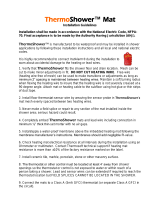
Components
plywood
or concrete slab
aluminum
sheath
ground
wire
heating
wires
aramid fiber
roving
floor heating
system
heating cable
aramid fiber roving
heating cable
PVC sheath
ground wire
(bare wire)
Two-phase conductor
120V: phase - neutral
240V/208V: phase - phase
junction
cold lead
cold lead
self-levelling
cement
cement glue
floor covering
wire
insulation
channel
Fig. 1.1

6
1.2 Always
• Read this guide in full before installing the product;
• Install the EFMA system with a regulating device;
• Use copper wires only;
• Perform the mandatory tests described in this guide and record readings on the
table of measures;
• Only use cement or an equivalent binder compatible with oor heating systems
(cement glue, ceramic glue, self-levelling cement);
• Ensure that the black heating cable is completely embedded in cement or an equiv-
alent binder (cement glue, ceramic glue, self-levelling cement);
• Ensure that the voltage supplied equals the nominal voltage of the EFMA system;
• Repair the product only using the EFMA repair kit available at your authorized
REZNOR dealer;
• Consult REZNOR’s team of technical specialists for any questions or for more
information;
• Install EFMA at temperatures over 5°C (40°F).
• Heating cables must be at least 13mm (½”) away from any combustible surface.
• Metal structures or materials used for the support of or on which cables or sets
are installed be grounded in accordance with the Canadian Electrical Code (CSA
C22.1 Section 10 and National Electrical Code).
• e installer of series heating cable sets must inspect and remove damaged or
defective heating cable sets before they are covered or concealed;
• e installer of series heating cable sets must mark the appropriate circuit breaker
reference (label) indicating which branch circuit supplies the circuit to those
electric heating cables.

7
2. Technical information
1.3 Never
• Install EFMA sections so that the heating cables are less than 76mm (3”) from each
other. e temperature could be too high and could cause damages;
• Shorten or alter any part of the heating cable (Fig. 1.3);
• Cross, overlap, or stack heating cables (they must not touch);
• Connect a 120V product to a 240V/208V power source;
• Use a bending radius under 20mm (¾”);
• Install a temperature regulator (thermostat or other) where it is accessible from the
shower or bath (install at least 1m [3’ 4”] away);
• Staple heating cable or oor sensor end to the suboor (Fig. 1.3);
• Install the EFMA system if the safety seal is broken;
• Install the EFMA system under a closet or xed items.
• Series heating cable sets shall not extend from beyond the room or area in which
they originate;
• Series heating cable sets are not to be installed in walls.
N
e
v
e
r
c
u
t
t
h
e
h
e
a
t
i
n
g
c
a
b
l
e
N
e
v
e
r
s
t
a
p
l
e
t
h
e
h
e
a
t
i
n
g
c
a
b
l
e
t
o
t
h
e
s
u
b
o
o
r
N
e
v
e
r
s
t
a
p
l
e
t
h
e
o
o
r
s
e
n
s
o
r
t
o
t
h
e
s
u
b
o
o
r
D
o
n
o
t
l
a
y
h
e
a
v
y
i
t
e
m
s
o
n
E
F
M
A
c
a
b
l
e
Fig. 1.3

8
2. Technical Information
2.1 Surface Area and Power Output of EFMA Products
Product #
120V
Width Length Surface area Power
Resistance
in. . sq.. Watt s Ohm
EFMA85AK1ELNG1 16 6’ 8 85 169.4
EFMA120AK1ELNG1 16 7’ 6” 10 120 120.0
EFMA150AK1ELNG1 16 10’ 13 150 96.0
EFMA170AK1ELNG1 16 11’ 6” 15 170 84.6
EFMA240AK1ELNG1 16 15’ 20 240 59.9
EFMA300AK1ELNG1 16 19’ 25 300 47.5
EFMA360AK1ELNG1 16 22’ 6” 30 360 39.6
EFMA420AK1ELNG1 16 26’ 6” 35 420 33.7
EFMA475AK1ELNG1 16 30’ 40 475 29.8
EFMA600AK1ELNG1 16 37’ 6” 50 600 23.3
EFMA720AK1ELNG1 16 45’ 60 720 19.0
EFMA840AK1ELNG1 16 52’ 6” 70 840 16.2
EFMA960AK1ELNG1 16 60’ 80 960 14.2
EFMA840AK1ELNG2 32 26’.3” 70 840 16.2
EFMA960AK1ELNG2 32 30’ 80 960 14.2

9
Product #
240V/208V
Width Length Surface area Power
Resistance
in. . sq.. Watts Ohm
EFMA170AK3ELNG1 16 11’ 6” 15 170 338.8
EFMA240AK3ELNG1 16 15’ 20 240 240.0
EFMA300AK3ELNG1 16 19’ 25 300 192.0
EFMA360AK3ELNG1 16 22’ 6” 30 360 159.8
EFMA420AK3ELNG1 16 26’ 6” 35 420 137.0
EFMA475AK3ELNG1 16 30’ 40 475 121.1
EFMA600AK3ELNG1 16 37’ 6” 50 600 95.0
EFMA720AK3ELNG1 16 45’ 60 720 79.2
EFMA840AK3ELNG1 16 52’ 6” 70 840 67.4
EFMA960AK3ELNG1 16 60’ 80 960 59.0
EFMA1080AK3ELNG1 16 67’ 6” 90 1080 51.8
EFMA1200AK3ELNG1 16 75’ 100 1200 46.6
EFMA1440AK3ELNG1 16 90’ 120 1440 37.9
EFMA1600AK3ELNG1 16 105’ 140 1600 34.1
EFMA1920AK3ELNG1 16 120’ 160 1920 28.4
EFMA840AK3ELNG2 32 26’.3” 70 840 67.4
EFMA960AK3ELNG2 32 30’ 80 960 59.0
EFMA1080AK3ELNG2 32 33’.9” 90 1080 51.8
EFMA1200AK3ELNG2 32 37’.6” 100 1200 46.6
EMFA1440AK3ELNG2 32 45’ 120 1440 37.9
EFMA1600AK3ELNG2 32 52’.6” 140 1600 34.1
EFMA1920AK3ELNG2 32 60’ 160 1920 28.4
208V=75% of wattage at 240V.

10
2.2 Insulation Test
Measure EFMA’s insulation resistance at each step using a megohmeter (Fig.
2.2) and record readings on the measures’table (this label is available at the
opening of the product).
IMPORTANT!
For the warranty to be valid, ll out the measures’ table and ensure that the
10 readings have been correctly noted.
A qualied electrician must measure the system’s insulation resistance as follows:
• Use a calibrated megohmeter only;
• Measure insulation resistance at the free end of the cold lead, between the phase
conductor and ground;
cold lead
Fig. 2.2
CAUTION! Dangerous Test
• Write the reading in the measures’table;
• is reading must be over 1,000,000ohms;
• If the reading is under 1,000,000ohms, stop work and contact REZNOR’s technical
specialists at 1800695-1901.

11
2.3 Resistance Test
Measure the resistance of the EFMA heating cable at each step using a multi-
meter (Fig. 2.3) and record readings on the measures’table.
IMPORTANT!
For the warranty to be valid, ll out the measures’ table and ensure that the
10 readings have been correctly noted.
A qualied electrician must measure the system’s resistance as follows:
• Use a calibrated multimeter only;
• Measure resistance at the free end of the cold lead, between the two phase
conductors;
cold lead
Fig. 2.3
• Write the reading in the measures’table;
• Verify the heating cable integrity by comparing your reading to the value on the
cold lead label;
• If your reading is o (see Table 2.1) at any step, stop work and contact REZNOR’s
technical specialists at 1800695-1901.

12
3. Types of Heating and Floor Covering
e EFMA oor heating system can be used for two purposes maximizing comfort.
Used as a secondary heat source (oor warming), it can help keep oor temperature
comfortable year round. Used as a primary room heat source (radiant oor heating),
it provides uniform, comfortable, and enveloping warmth. For the latter use, it is
important to follow the specic recommendations outlined below.
In light of environmental factors beyond REZNOR’s control—including thermal
insulation, heated area, oor covering emissivity, heat loss, and more—we cannot
guarantee that the EFMA system will provide a completely uniform surface temper-
ature in all cases, no matter how careful the installation. Consequently, REZNOR
cannot be held liable for any discomfort (e.g., a cold area on the oor) caused by site-
specic deciencies.REZNOR liability is limited to the performance of its products.
3.1 Floor Warming
is type of heating is designed to enhance comfort and/or supplement the room’s
main heat source. It helps keep the oor at a pleasant temperature at all times.
Installing this type of system is very easy: simply unroll the EFMA adhesive oor
heating system directly on the oor, embed the heating cable in cement or an equiv-
alent binder (cement glue, ceramic glue, self-levelling cement) and install the oor
covering. Use the oor coverings listed in Section3.3 and connect the EFMA system
to an appropriate thermostat, described in Section5.
3.2 Radiant Floor Heating
EFMA can be used as the room’s primary heat source. It can heat the room using the
EFMA system only. Proceed as follows:
• Connect the system to an ambient temperature regulator;
• Calculate heat loss to ensure the system has enough power to heat the room;
• Sucient insulation under the suboor is very important. is insulation is to be
sure that the heat will rise into the room to be heated.
• Make sure to have a oor covering that meets the specications listed in Table3.3.

13
IMPORTANT!
Do not install a radiant oor heating system on a noninsulated or poorly insulated
suboor, or over a crawl space.
e eciency of this type of primary room heating system will depend on factors such
as surface area, heat conductivity of the oor covering, insulation on outside walls,
etc. We recommend that you verify these points and seek professional advice before
investing time and money.
3.3 Typical Floor Coverings
IMPORTANT!
e thermal resistance of the oor covering must not exceed R=1.40 (RSI=0.246).
ere is no such limit for the suboor.
Table 3.3 ermal resistance values for oor coverings
Typical oor covering
ermal resistance
R RSI
Vinyl tiles 0.20 0.035
Linoleum 0.22 0.039
Ceramic 0.25 0.044
Low-pile carpet 0.70 0.123
Parquet ooring 0.70 0.123
Floating oor 10mm to 16mm (
3
/
8
” to
5
/
8
”) 0.70 0.123
Wood on lathes (strapping)* 2.10 0.368
* e oor covering highlighted in grey is prohibited.
IMPORTANT!
For engineered wood oorings, laminated hardwood ooring, vinyl coverings, and
linoleum glued to a concrete surface, consult your oor covering manufacturer to
ensure they are compatible with oor heating systems.

14
4. Installation Instructions
4.1 Planning Work
Materials provided by REZNOR
• EFMA oor heating system roll
• Installation instructions
• Electrical panel label
• Floor temperature sensor
Material required
• Temperature control with GFCI (available at REZNOR)
• Cable check tester (available at REZNOR)
• Stapler
• Protective glasses
• Measuring tape
• Broom
• Mop and bucket
• Felt marker
• Tape
• Hot glue gun
• Wood chisel
• Hammer
• Multimeter and megohmeter
• Electrician tools
• Electrical tape
For installation over a concrete slab, add the following:
• Spray adhesive
• Concrete chisel
Room Layout and Corresponding EFMA Product
• Create a room layout plan to scale (for maximum accuracy, use the REZNOR form
designed for this purpose);
• Identify all stationary elements (toilet, bath, shower, counters, drawers, and
permanent furnishings) and never install the heating cable under these stationary
elements (Fig. 4.1);
• Determine thermostat or temperature control location;
• Note room dimensions;
• Determine cold lead location;
• Calculate the heating area in square feet (sq..);
• Select the EFMA product from Table 2.1 to cover 80% of the surface, or subtract a
mimimum of 50mm (2”) around walls and stationary elements.

15
Fig. 4.1
cold lead
temperature
sensor
10'
8'
We can help optimize your work plan. Fax it to us at 724-662-3957. Clearly
indicate all dimensions. A minimum of one horizontal and one vertical
dimensions are necessary to validate the scale.
4.2 Preparing the Suboor
• Clean and remove any debris, dust or protruding objects that could damage the
heating cable. e surface must be clean and dry for the adhesive mat to adhere
perfectly to the suboor;
• Suboor cracks must be lled with polyester wood ller;
• e suboor must be solidly fastened in place to prevent movement;
• e application of a oor levelling product is recommended to prevent future
damage to the ceramic caused by suboor movement;
• For concrete suboors, apply a surface sealer that is compatible with electrical
heating systems in accordance with the cement glue manufacturer’s instructions.
Completely coat the surface;
• Let dry before installing the EFMA system (refer to the sealer’s instructions for
drying time).
4.3 Marking the Floor
Felt marker
• On the oor of an empty room (under construction or major renovations), draw the
location of stationary elements (toilet, bath, shower, counters, drawers, permanent
furnishings) that will be installed later. ese marks will outline the heating area to
ensure the EFMA system is not placed under these stationary elements (Fig. 4.3 a);
• Draw lines on the oor the width of the mat 0.41m (16”) or 0.82 m (32”);
• Indicate in which direction the EFMA system will be unrolled;

16
16"
Fig. 4.3 a
• e oor temperature sensor must be centered between two parallel heating cables
under the EFMA berglass mat (Fig. 4.3 b). e ideal location is one where it is
likely to be away from stationary objects and sheltered from outside inuences
(sunlight) that could skew oor temperature readings. For maximum comfort, the
area above the sensor must be free of obstruction.
10"
16"
Fig. 4.3 b

17
4.4 Installing the EFMA Floor Heating System
Tape, spray adhesive, stapler
Remove the product from the box and verify the electrical and insulation
resistance of the heating cable.
heating cable
junction
channel
cold lead
Fig. 4.4 a
• Unroll the mat, adhesive side down (Fig. 4.4 a);
• Ensure that the cold lead is long enough to be connected to the thermostat or
junction box;
• To minimize oor height, chisel a 10mmX10mmX250mm (
3
/
8
”X
3
/
8
”X10”)
channel in the suboor to receive the cold lead/heating cable (black) junction.
e junction has an extra insulation sheath and a slightly larger diameter than the
heating cable;
• Continue to unroll the EFMA system on the oor, working around the stationary
elements marked out beforehand (see Section 4.4.1);
• As needed, reposition EFMA: its adhesive allows it to be positioned more than
once.
• You may use hot glue or tape to fasten the EFMA to the suboor;

18
• Staple the mat to the plywood suboor to prevent the mat ends from curling;
• Use spray adhesive to fasten the EFMA to a concrete suboor.
Staple the mat to plywood
Secure with an aerosol adhesive
on concrete
Fig. 4.4 b Fig. 4.4 c
IMPORTANT!
Never staple the heating cable directly to the suboor.
4.4.1 Working Around Walls and Obstacles
90°
180°
Cut the mat
NEVER CUT
OR SHORTEN
THE HEATING CABLE
Change direction 90°
when you meet
an obstacle
Change direction 180°
when you meet
an obstacle
Work around
obstacles
Work around a 45° wall
Obstacle
Fig. 4.4 1
• When the EFMA roll meets a wall or obstacle, simply cut the mat and pivot it in
another direction (Fig. 4.4.1);

19
IMPORTANT!
Never cut or try to shorten the heating cable.
• Ensure that the EFMA surface is at against the suboor;
• Avoid walking on the EFMA system. If you must, wear so rubber soled shoes;
• Always start unrolling EFMA at least 50mm (2”) from the walls;
• To work around stationary elements, detach a section of heating cable from the mat
and use it to cover a tight space or work around an object;
• It is important not to subject the heating cable to any mechanical strain (stretching,
radius bending under 20mm [¾”], scoring).
4.4.2 Mat Rippling
• Carefully atten the mat against the suboor to ensure it and the heating cable can
be completely embedded in the cement or other binder to be applied in the next
step;
• If the mat ripples, score the center of the rippled section and atten the edges (Fig.
4.4.2).
Fig. 4.4 2
IMPORTANT!
Never cut or score the heating cable.
Measure the cable’s electrical and insulation resistance and record the
readings on line 2) Aer installing the heating cable of the
measures’table.

20
4.5 Installing the Temperature Sensor
Hot glue gun, hammer, wood chisel or concrete chisel
channel
temperature
sensor
Fig. 4.5
• To minimize oor height, chisel a 10mmX10 mmX250mm (
3
/
8
”X
3
/
8
”X10”)
channel in the suboor to receive the temperature sensor.
CAUTION!
e sensor must be embedded in cement or an equivalent binder (cement glue,
ceramic glue, self-levelling cement).
• Glue the sensor to the suboor (Fig. 4.5). e sensor must be solidly fastened to
the suboor to ensure it stays in place when the cement or an equivalent binder
(cement glue, ceramic glue, self-levelling cement) is applied.
/