Page is loading ...

by
Body-Solid
®
Assembly Instructions

1
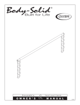
Be careful to assemble all components
in the sequence they are presented.
mm
Inch
2
NOTE:
Finger tighten all hardware in this step. Do Not
wrench tighten until end of step 3.
STEP
A. Attach two Foot Caps (4) to Rear Base Frame (B) as shown.
B. Attach Main Base Frame (A), Flat Plate (114) and Guide Rods (E) to Rear Base Frame (B) using:
Two 50 (3/8” x 3” hex head bolt)
Four 74 (3/8” washer)
Two 72 (3/8” nylon lock nut)
Slide two Weight Stack Risers (38)* and two Rubber Donuts (14) onto Guide Rods (E).
*NOTE:
Use the two Weight Stack Risers (38) if you have a 160lb. weight stack.
If you have a 210lb. weight stack you will not
need the two Weight Stack Risers (38), they
can be discarded.
C. Attach Grip Tape (121) to the bottom of Front Base Frame (C).
D. Attach Front Base Frame (C) to Main Base Frame (A) using the two Low Side Panels (D) and using:
Five 47 (3/8” x 4” hex head bolt)
Ten 74 (3/8” washer)
Five 72 (3/8” nylon lock nut)
Attach Frame Leveler (138) to the bottom of Main Base Frame (A).

1
3
STEP
RED DOT
USE THE TWO WEIGHT
STACK RISERS (38) FOR
A 160lb. WEIGHT STACK.
IF YOU HAVE A 210lb.
WEIGHT STACK OMIT
THE TWO WEIGHT
STACK RISERS (38).

mm
Inch
2
Be careful to assemble all components
in the sequence they are presented.
4
STEP
A. Slide Weight Stack Plates (37)* onto Guide Rods (E). Make sure the opening in each Weight
Stack Plate (37), for the Weight Stack Pin (60), is facing for
ward.
*NOTE:
Use fifteen 10lb. plates for a 160lb. weight stack.
Use twenty 10lb. plates for a 210lb. weight stack. See NOTE after Step 1B.
B. Selector Rod Top Bolt (101) and hardware are pre-installed into the Selector Rod (23).
Connect Top Plate (22) to the Selector Rod (23) using:
One 53 (3/8” x 2” socket head bolt)
One 140 (3/8” spring lock washer)
Slide Top Plate (22) and Selector Rod (23) onto Guide Rods (E).
C. Slide two Shaft Collars (12) onto the two Guide Rods (E) as shown.
D. Insert Guide Rods (E) into Rear Arch Post (F), and attach both Rear Arch Posts (F) to Rear Base
Frame (B) using:
Four 44 (1/2” x 3 1/2” hex head bolt)
Eight 73 (1/2” washer)
Four 71 (1/2” nylon lock nut)
E. Slide Shaft Collars (12) up into the Rear Arch Post (F) and turn the Shaft Collar, so it locks onto
the Rear Arch Post (F), Now tighten each Allen Screw (111) in Shaft Collars (12).
NOTE:
Finger tighten all hardware in this step. Do Not
wrench tighten until end of step 3.

2
5
STEP
RED DOT
YELLOW
DOT

Be careful to assemble all components
in the sequence they are presented.
mm
Inch
3
6
STEP
A. Attach two Top Panels (G) to Rear Arch Post (F) and install Pulley (17) using:
Two 46 (3/8” x 4 1/4” hex head bolt)
One 7 (5/8” x 3” spacer)
Two 5 (5/8” x 1” spacer sleeve)
Four 74 (3/8” washer)
Two 72 (3/8” nylon lock nut)
B. Attach End Cap (3) to the top of Panel Spacer (H) as shown.
Attach Panel Spacer (H) between the two Top Panels (G) using:
Two 48 (3/8” x 3 3/4” hex head bolt)
Four 74 (3/8” washer)
Two 72 (3/8” nylon lock nut)
C. Attach Vertical Frame (J) to Front Base Frame (C) and Flat Plate (115) using:
One 42 (1/2” x 3” hex head bolt)
One 41 (1/2” x 3 1/4” hex head bolt)
Three 73 (1/2” washer)
One 71 (1/2” nylon lock nut)
D. Attach Vertical Frame (J) between Top Panels (G) using:
Two 48 (3/8” x 3 3/4” hex head bolt)
Four 74 (3/8” washer)
Two 72 (3/8” nylon lock nut)
Attach two End Caps (2) to Vertical Frame (J) as shown.
NOTE:
At this point you must make sure that the gym is level, stable and in the right location.
You should now wrench tighten all bolts and nuts on the mainframe unit only.
Also, leave all pulley bolts finger-tight until after STEP 14.
E. Attach Water Bottle Bracket (116) to the left Rear Arch Post (F) into the appropriate holes
using:
Two 118 (1/8” x 3/8” screw)
Two 119 (1/8” washer)
F. Slide the Water Bottle holder (117) onto the Water Bottle Bracket (116).
Water Bottle (120) will fit into Water Bottle Holder (117).

3
7
STEP

4
Be careful to assemble all components
in the sequence they are presented.
mm
Inch
8
STEP
A. Attach Right Seated Press Arm (K) and Left Seated Press Arm (L) to Vertical Frame (J) With
Shaft (128) using:
Two 39 (1/2” x 3/4” hex head bolt)
Two 73 (1/2” washer)
Tighten Allen Screws (111) in Vertical Frame (J).
B. Attach two Round End Caps (26) to Left Seated Press Arm (L), and attach two Round
End Caps (26) to Right Seated Press Arm (K) as shown.
C. Attach Pivot (P) to Right Seated Press Arm (K) using as shown:
Two 81 (3/8” x 5/8” allen bolt)
Two 82 (3/8” washer)
D. Attach Right Press Handle (M) to Pivot (P) on Right Seated Press Arm (K) using Shaft (129)
as shown:
Two 81 (3/8” x 5/8” allen bolt)
Two 82 (3/8” washer)
E. Attach Pivot (P) to Left Seated Press Arm (L) using as shown:
Two 81 (3/8” x 5/8” allen bolt)
Two 82 (3/8” washer)
F. Attach Left Press Handle (N) to Pivot (P) on Left Seated Press Arm (L) using Shaft (129) as shown:
Two 81 (3/8” x 5/8” allen bolt)
Two 82 (3/8” washer)
G. Attach Press Handle Holder (139)* to Right Seated Press Arm (K) using:
One 85 (3/8” x 3 1/4” allen head bolt)
Two 74 (3/8” washer)
One 72 (3/8” nylon lock nut)
*NOTE:
One Press Handle Holder (139) is marked with an R, and should be installed with the R
on top.
H. Attach Press Handle Holder (139)* to Left Seated Press Arm (L) using:
One 85 (3/8” x 3 1/4” allen head bolt)
Two 74 (3/8” washer)
One 72 (3/8” nylon lock nut)
*NOTE:
One Press Handle Holder (139) is marked with an L, and should be installed with the L
on top.

4
9
STEP
marked
with L
and a
RED dot
marked
with R
and a
YELLOW
dot

5
Be careful to assemble all components
in the sequence they are presented.
mm
Inch
10
STEP
A. Attach two Leg Hold Downs (Q) and (R) to Vertical Frame (J) using:
Two 46 (3/8” x 4” hex head bolt)
Four 74 (3/8” washer)
Two 72 (3/8” nylon lock nut)
B. Attach two Foam Rollers (21) onto each of the Leg Hold Downs (Q) and (R) and hold in place
with Roller End Cap (9) as shown.
C. Attach Back Pad Holder (S) to Vertical Frame (J) using:
Two 40 (1/2” x 4” hex head bolt)
Four 73 (1/2” washer)
Two 71 (1/2” nylon lock nut)
D. Insert two Nylon Bushings (25) into Back Pad Holder (S).
Insert End Cap (1) into the end of Back Pad Adjuster (T).
Slide Back Pad Adjuster (T) into Back Pad Holder (S) and hold in place with T-shaped
Pop Pin (79) and Socket Head Bolt (137) as shown.
E. Insert two End Caps (24) to the top and bottom of Back Pad Frame (V).
Attach Back Pad (U) to Back Pad Frame (V) using:
Two 56 (5/16” x 1 3/4” hex head bolt)*
Two 77 (5/16” spring lock washer)
Two 75 (5/16” washer)
*Note:
Do not over tighten pad bolts (87), over tightening will strip the T-nuts pressed into the
wood
.
F. Attach Back Pad Frame (V) to Back Pad Adjuster (T) with T-shaped Pop Pin (80) and:
One 81 (3/8” x 5/8” allen bolt)
One 82 (3/8” washer)

5
11
STEP

6
Be careful to assemble all components
in the sequence they are presented.
mm
Inch
12
STEP
A. Seat Pad Frame (AA) is pre-installed into Front Base Frame (C).
B. Attach two Foam Rollers (21) to Seat Pad Frame (AA) using Foam Roller Bar (X).
Hold Foam Rollers (21) in place with Plastic Washer (13) on the inside and Roller End Cap (9) on the
outside as shown.
C. Insert End Cap (3) to the back of Seat Pad Frame (AA).
Attach Seat Pad (Z) to Seat Pad Frame (AA) using:
Two 55 (5/16” x 2 3/4” hex head bolt)*
Two 77 (5/16” spring lock washer)
Two 75 (5/16” washer)
*Note:
Do not over tighten pad bolts (55), over tightening will strip the T-nuts pressed into the wood
.
.

6
13
STEP

7
mm
Inch
14
STEP
A. Insert End Cap (3) to the top of Leg Extension (W).
Attach Leg Extension (W) to the Front Base Frame (C) with Shaft (126) and the pre-installed
hardware:
Two 83 (5/16” x 5/8” allen bolt)
Two 84 (5/16” washer)
B. Attach Leg Pad Holder (AB) onto Leg Extension (W) using:
One 88 (1/2” x 5 1/2” hex head bolt)
Two 73 (1/2” washer)
One 71 (1/2” nylon lock nut)
C. Attach two Leg Pads (AC) to Leg Pad Holder (AB) using:
Four 87 (5/16” x 3/4” allen head bolt)*
Four 77 (5/16” spring lock washer)
Four 75 (5/16” flat washer)
*Note:
Do not over tighten pad bolts (87), over tightening will strip the T-nuts pressed into
the wood.
D. Attach 5/16” wide Spacer (202) and two 1/2” Washers (73) to the end of the 1/2” x 5 1/2” Hex
Head Bolt (88) that is attaching the Leg Pad Holder (AB) as shown in the Reverse Side Drawing
using:
One 71 (1/2” nylon lock nut)
E. Attach L-Bracket (203) to the Front Base Frame (C) using Jam Nut (109) and Plastic Stop (110)
as shown.
Attach Jam Nut (70) onto L-Bracket (203) first, this will give you the proper spacing for the Lock
Down Hook (200).
Slide one 1/2” Washer (73), then slide the 1/4” wide Spacer (201) onto the L-Bracket (203).
Slide the Lock Down Hook (200) onto the 1/4” wide Spacer (201), and hold in place using:
One 73 (1/2” washer)
One 71 (1/2” nylon lock nut)
Be careful to assemble all components
in the sequence they are presented.

15
REVERSE SIDE DRAWING
7
STEP

8
Be careful to assemble all components
in the sequence they are presented.
mm
Inch
16
STEP
A. Insert Wide Pulley (20) into Leg Extension (W) and hold in place using:
One 51 (3/8” x 2 3/4” hex head bolt)
Two 74 (3/8” washer)
One 72 (3/8” nylon lock nut)
B. Insert 3” Pulley (18) into Front Base Frame (C) and hold in place using:
One 51 (3/8” x 2 3/4” hex head bolt)
Two 10 (pulley spacer)
One 72 (3/8” nylon lock nut)
C. Attach three Pulleys (17) and three Pulley Covers (BA) onto the left side of the Top Side Panels (G).
also, attach three Pulleys (17) and three Pulley Covers (BA) onto the right side of the Top
Side Panels (G) as shown using:
Three 45 (3/8” x 6 1/2” hex head bolt)
Six 74 (3/8” washer)
Six 8 (1/4” spacer sleeve)
Three 7 (3” spacer sleeve)
Three 72 (3/8” nylon lock nut)

8
17
STEP

9
Be careful to assemble all components
in the sequence they are presented.
mm
Inch
18
STEP
A. Attach Weight Stack Cable (32) between Top Side Panels (G) using:
One 48 (3/8” x 3 3/4” hex head bolt)
Two 74 (3/8” washer)
Two 7 (spacer sleeve)
One 72 (3/8” nylon lock nut)
B. Route Cable (32) through the Double Pulley Holders (BB) and hold Pulley (A1) in place using:
One 52 (3/8” x 1 3/4” hex head bolt)
Two 74 (3/8” washer)
One 72 (3/8” nylon lock nut)
C. Route Cable (32) up and between Top Side Panels (G).
Route Cable (32) around Pulley (A2) and install Pulley (A2) between Top Side Panels (G) using:
One 48 (3/8” x 3 3/4” hex head bolt)
Two 74 (3/8” washer)
Two 5 (spacer sleeve)
One 72 (3/8” nylon lock nut)
D. Route Cable (32) through Single Pulley With Hook (BC) and around Pulley (A3).
Install Pulley (A3) using:
One 52 (3/8” x 1 3/4” hex head bolt)
Two 74 (3/8” washer)
One 72 (3/8” nylon lock nut)
Attach Rubber Pad (28) to the top of Single Pulley With Hook (BC) as shown.
Weight Stack Cable (32)
Stamped Eye End
Metal Ball End
2670mm 8’ 9”

9
STEP
19
Diagram 1
Cable Installation
Weight
Stack Cable
Start by attaching the Cable (32) between
the Top Side Panels (G) here.
Diagram 2
Pulley Installation

10
Be careful to assemble all components
in the sequence they are presented.
mm
Inch
20
STEP
A. Route Cable (32) up and around pre-installed Pulley (A5). Leave Cable (32) hanging down toward the
weight stack.
Install 3” Pulley (A4) under
Cable (32) using:
One 48 (3/8” x 3 3/4” hex head bolt)
Two 74 (3/8” washer)
Two 5 (spacer sleeve)
One 72 (3/8” nylon lock nut)
B. See Diagram 1A. The Metal Ball End of Cable (32) should be hanging just above the weight
stack. Remove Bolt (100) from Selector Rod Top Bolt (101), slide Metal Ball End of Cable (32)
through Selector Rod Top Bolt (101). Attach Cable End Shaft (62) and securely tighten
Allen Screw (104). Pull Cable (32) tight, so Cable End Shaft (62) fits securely inside Selector Rod
Top Bolt (101). Reinstall Bolt (100) in Selector Rod Top Bolt (101).
NOTE:
Make sure the Selector Rod Top Bolt (101) is threaded inside Selector Rod (23) at least
one half inch. Make sure Spring Lock Washer (102) is in place and wrench tighten Jam
Nut (103).
Weight Stack Cable (32)
Stamped Eye End
Metal Ball End
2670 mm
8’ 9”
/