
INSTALLATION
AND
OPERATING
INSTRUCTIONS
P/N 8835500 2-09
1
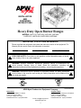
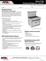
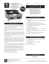
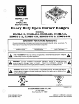
Heavy Duty Open Burner Ranges
MODELS: HHP-212, HHP-424, HHP-636, HHP-848
HHPS-212, HHPS-424, HHPS-636, HHPS-848
Please complete this information and retain this manual for the life of the equipment. For
Warranty Service and/or Parts, this information is required.
Model Number Serial Number Date Purchased
IMPORTANT FOR FUTURE REFERENCE
FOR YOUR SAFETY: Do not store or use gasoline or other flammable vapors or liquids
in the vicinity of this or any other appliance.
WARNING: Improper installation, adjustment, alteration, service or maintenance can
cause property damage, injury or death. Read the installation, operating and
maintenance instructions thoroughly before installing, or servicing this equipment.
WARNING: Instructions must be posted in a prominent location. All safety precautions
must be taken in the event the user smells gas. Safety information can be obtained from
your local gas supplier.
LISTED
GAS-FIRED
US
C
U
L
ANSI/NSF4
U
L
EPH
APW Wyott Foodservice Equipment Company
E-mail: [email protected]
www.apwwyott.com
Dallas Plant
729 Third Ave. Dallas, TX 75226
Local: 1-(214) 421-7366
Toll Free: 1-(800) 527-2100
Parts/Service Fax: 1-(214) 565-0976
Cheyenne Plant
1938 Wyott Drive, Cheyenne, WY 82007
Local: 1-(307) 634-5801
Toll Free: 1-(800) 752-0863
Parts/Service Fax: 1-(307) 772-0460

TABLE OF CONTENTS:
2
LOCATION OF DATA PLATE
The data plate for the gas open burner range is located on the right side panel.
IMMEDIATELY INSPECT FOR SHIPPING DAMAGE
All containers should be examined for damage before and during unloading. The freight carrier has
assumed responsibility for its safe transit and delivery. If equipment is received damaged, either apparent or
concealed, a claim must be made with the delivering carrier.
A) Apparent damage or loss must be noted on the freight bill at the time of delivery. It must then be signed by
the carrier representative (Driver). If this is not done, the carrier may refuse the claim. The carrier can supply
the necessary forms.
B) Concealed damage or loss if not apparent until after equipment is uncrated, a request for inspection
must be made to the carrier within 15 days. The carrier should arrange an inspection. Be certain to hold all
contents and packaging material.
Installation and start-up should be performed by a qualified installer who thoroughly read, understands and
follows these instruction.
If you have questions concerning the installation, operation, maintenance or service of this product, write
Technical Service Department APW Wyott Foodservice Equipment Company, 1938 Wyott Drive,
Cheyenne, WY 82007.
Before installing and operating this equipment be sure everyone involved in its operation is fully trained and
is aware of all precautions. Accidents and problems can result by a failure to follow fundamental rules and
precautions.
Shut off gas flow through the appliance before cleaning or servicing unit.
The following words and symbols, found in this manual, alert you to hazards to the operator, service
personnel or the equipment. The words are defined as follows.
1. SAFETY PRECAUTIONS
SECTION ITEM PAGE
1 Safety Precautions.......................................................................................................2
2 General Installation Instructions ..................................................................................4
3 Specifications...............................................................................................................4
4 Lighting Instructions.....................................................................................................7
5 Maintenance ................................................................................................................8
6 Conversion...................................................................................................................9
7 Replacement Parts Lists & Exploded View.................................................................11
8 Warranty .....................................................................................................................16

3
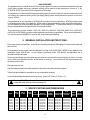
DANGER: This symbol warns of imminent hazard which will result in serious injury or
death.
WARNING: This symbol refers to a potential hazard or unsafe practice, which could result
in serious injury or death.
CAUTION: This symbol refers to a potential hazard or unsafe practice, which may result in
minor or moderate injury or product or property damage.
NOTICE: This product is intended for commercial use only. Not for household use.
CAUTION: These models are designed, built, and sold for commercial use. If these
models are positioned so the general public can use the equipment make sure that
cautions, warnings, and operating instructions are clearly posted near each unit so that
anyone using the equipment will use it correctly and not injure themselves or harm the
equipment.
WARNING: Improper installation, adjustment, alteration, service or maintenance can
cause property damage, injury or death. Read installation, operating and maintenance
instructions thoroughly before installing or servicing this equipment.
NOTICE: This symbol refers to information that needs special attention or must be fully
understood even though not dangerous.
WARNING: For your safety do not store or use gasoline or other flammable vapors or
liquids in the vicinity of this or any other appliance. Keep the area free and clear of
combustibles. (SeeANZI Z83.14B, 1991)
NOTICE: Local codes regarding installation vary greatly from one area to another. The
National Fire Protection Association, Inc., states in its NFPA96 latest edition that local
codes are “Authority Having Jurisdiction” when it comes to requirement for installation of
equipment. Therefore, installation should comply with all local codes.
NOTICE: Instructions to be followed if anyone smells gas should be posted in a prominent
place. These may be obtained from the gas supplier.
WARNING: Do not turn on gas valves without lighting pilot. A build up of gas and possible
explosion could occur.
GENERAL INFORMATION
THIS MANUAL SHOULD BE RETAINED FOR FUTURE REFERENCE
!
!
WARNING: A factory authorized agent should handle all maintenance and repair. Before
doing any maintenance or repair, contact APW Wyott.

2. GENERAL INSTALLATION INSTRUCTIONS:
Ensure gas supply and gas type, as shown on unit data plate agree. (Data plate is located on the right side
panel of unit).
Unit installation must conform with the National Fuel Gas Code, ANSI Z223.1/NFPA 54, the National Gas
Installation Code, CSA B149.1, or the Propane Installation Code, CSA B149.2 as applicable and in
accordance with local codes.
Screw legs into the permanently fastened nuts on the four corners of the unit and tighten by hand. Level the
unit by turning the adjustment screw at the bottom of each leg. Do not slide unit with legs mounted, lift if
necessary to move unit.
Pipe gas supply to unit.
Pipe threading compound must be resistant to the action of liquefied petroleum gases.
These units are suitable for installation on non-combustible surfaces.
Unit must have adequate clearances for servicing. (Sides = 0”, Rear = 0”, Floor = 4”)
4
3. SPECIFICATIONS AND DIMENSIONS
GAS PRESSURE
The appliance and it’s individual shutoff valve (to be supplied by user) must be disconnected from the gas
supply piping system during any pressure testing of that system at test pressures in excess of ½ psi
(3.45 kPa).
The appliance must be isolated from the gas supply piping system by closing it’s individual manual shut-off
valve during any pressure testing of the gas supply piping system at test pressures equal to or less than
½ psi (3.45 kPa).
NOTE: Gas shutoff valve is supplied on CE models.
Congratulations on your purchase of APW Wyott commercial cooking equipment. APW Wyott takes pride
in the design and quality of our products. When used as intended and with proper care and maintenance,
you will experience years of reliable operation from this equipment. To ensure best results, it is important
that you read and follow the instructions in this manual carefully.
The countertop hot plate, models HHP-212, HHP-424, HHP-636, HHP-848, HHPS-212, HHPS-424,
HHPS-636 & HHPS-848 provides countertop heating and cooking capabilities. These units incorporate 2,
4, 6 or 8 burners at 30,000 BTU/Hr each for fast, even cooking and heating.
Warning: DO NOT use an open flame to check for leaks. Check all gas piping for leaks with
a soap and water solution before operating unit.
MODEL
WIDTH
IN. (MM)
DEPTH
IN. (MM)
HEIGHT
IN. (MM)
# OF
BURNERS
BTU/Kw PER
BURNER
NATURAL GAS
TOTAL
BTU/kW HOUR
NATURAL GAS
HHP-212 12" (305) 31.09" (789.7) 13.8" (351) 2 30,000 (8.79) 25,000 (8.32) 60,000 (17.6) 50,000 (14.64) 5 (12.4) 10 (24.9)
HHP-424 24” (610) 31.09" (789.7) 13.8" (351) 4 120,000 (35.2) 100,000 (29.29)
HHP-636 36” (914) 31.09" (789.7) 13.8" (351) 6 180,000 (52.7) 150,000 (43.93)
HHP-848 48” (1219) 31.09" (789.7) 13.8" (351) 8 240,000 (70.3) 200,000 (58.57)
HHPS-212 12" (305) 31.09" (789.7) 16.8" (427) 2 60,000 (17.6) 50,000 (14.64)
HHPS-424 24” (610) 31.09" (789.7) 16.8" (427) 4 120,000 (35.2) 100,000 (29.29)
HHPS-636 36” (914) 31.09" (789.7) 16.8" (427) 6 180,000 (52.7) 150,000 (43.93)
HHPS-848 48” (1219) 31.09" (789.7) 16.8" (427) 8 240,000 (70.3) 200,000 (58.57)
30,000 (8.79) 25,000 (8.32) 5 (12.4) 10 (24.9)
30,000 (8.79) 25,000 (8.32) 5 (12.4) 10 (24.9)
30,000 (8.79) 25,000 (8.32) 5 (12.4) 10 (24.9)
30,000 (8.79) 25,000 (8.32) 5 (12.4) 10 (24.9)
30,000 (8.79) 25,000 (8.32) 5 (12.4) 10 (24.9)
30,000 (8.79) 25,000 (8.32) 5 (12.4) 10 (24.9)
30,000 (8.79) 25,000 (8.32) 5 (12.4) 10 (24.9)
BTU/Kw PER
BURNER
PROPANE
TOTAL
BTU/kW HOUR
PROPANE
W.C. IN.
('MBAR')
NATURAL
GAS
W.C. IN.
('MBAR')
PROPANE

5
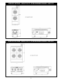
SPECIFICATIONS - HEAVY DUTY OPEN BURNER RANGE: HHP-212
21827000
SPECIFICATIONS - HEAVY DUTY OPEN BURNER RANGE: HHP-424
21827100

6
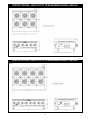
SPECIFICATIONS - HEAVY DUTY OPEN BURNER RANGE: HHP-636
21827200
SPECIFICATIONS - HEAVY DUTY OPEN BURNER RANGE: HHP-848
21827300

7
4. LIGHTING INSTRUCTIONS
HHP and HHPS Gas Open Burner Ranges are furnished with either a pilot safety valve or a standing pilot
(not available in the European Community). Please follow the instructions for your unit.
Operation of the gas valve pilot:
1. Turn knob on the main gas valve to the pilot position
2. Depress knob to start gas flow to the pilot valve
3. Light pilot valve
a. Using a match or taper
4. Hold in knob for 15 to 30 seconds to heat up the thermocouple
5. Release knob and turn to the desired gas flow position
a. If pilot goes out repeat steps 1-4, some thermocouples will take longer to heat up
( Not Available in the European Community )
The pilot lights on the broilers have been set at the factory. A screwdriver may be required for the first lighting
to adjust the flame for your elevation.
1. Turn off the manual shut off valve and wait 5 minutes to clear the gas.
2. Turn all knobs to the "OFF" position.
3. The valve can be accessed through an opening in the front panel or remove the cooking grates and
light the pilot from above.
4. Turn the manual shut off valve on.
5. Hold an ignition source (match) to both openings on the pilot tube. When the flames are established,
remove the ignition source.
6. Turn the burner knobs to “ ”. If the burner does not ignite, promptly open the pilot valve more. If the
pilot flame appears larger than necessary, turn it down and reset burner ignition. The pilot flame should
be as small as possible but large enough to guarantee reliable ignition of the burners when the knobs
are turned to .
If the pilot light should go out for any reason:
Promptly shut off all gas at the manual shut off valve.
Turn off all knobs and pilot valves; wait 5 minutes to clear gas.
Relight following steps 4 through 6 under
Since the burner is lit from constantly burning pilot, turn knobs to "HI" to put the unit in operation; then adjust
to any desired position between "LO" and "HI".
To light burner, turn knob to "max." then back off to the desired flame level. The range of adjustment is
virtually infinite between high and off. (At the small flame, there is a pre-set low).
When the broiler is first heated, it will smoke until oil used in manufacturing, preservation and dust from
storage and shipping are burned off. An hour at "max." on all burners is usually sufficient.
Turn knobs off and let cool
For first cooking, set the grates at maximum tilt position and preheat before broiling. You will have to
experiment with knob settings and grate position for each particular item.
Keep the grease/water pan with sufficient water to cover the entire bottom.
Clean regularly. Grates may be removed for washing in the sink. Brush out carbonized particles.
Thoroughly wash the grease/water pan.
Never attempt to move a grill section while cooking. An unexpected flare could cause severe injury. Turn off
the unit, let it cool and use potholders and/or gloves to reposition or remove. The space between the legs at
the bottom admits combustion air. DO NOT BLOCK THIS SPACE.
Pilot Operation Flame Failure Gas Valve:
Standing Pilot Lighting Instructions:
Standing Pilot Lighting Instructions.
LIGHTING THE MAIN BURNER:
CAUTION
HI
“HI”
RELIGHTING PILOT
l
l
l
l
l
l
l
l
l

Main burner air supply:
European Community:
If adjustment becomes necessary in the field, it should be done by a factory authorized and trained
technician who should seal the screw after the adjustment to safeguard against un-authorized
tampering by the end user.
For efficient burner operation, a proper balance of gas volume and primary air supply must be maintained
which will result in complete combustion. Insufficient air supply results in a yellow streaming flame. Primary
air supply is controlled by an air shutter on the front of the burner.
Loosen the screws on the front of the burner, and adjust the air shutter to just eliminate the yellow tips of the
burner flame. Lock the air shutter in place by tightening the screws.
All burners are lit from constantly burning pilots. Turning the valve to the desired flame height is all that is
required to put the unit in service.
Do not permit fans to blow directly at the unit. Wherever possible, avoid open windows next to the units'
sides or back. Avoid wall type fans which create air cross-currents within a room.
It is also necessary that sufficient air should be allowed to enter the room to compensate for the amount of air
removed by any ventilating system. Otherwise, a subnormal atmospheric pressure will occur, affecting
operation and causing undesirable working conditions.
A properly designed and installed hood will act as the heart of the ventilating system for the room or area in
which the unit is installed, and will leave the unit independent of changing draft conditions.
All valves must be checked and lubricated periodically. This must be done by an authorized service
representative in your area.
5. MAINTENANCE
CAUTION: Use only non-abrasive cleaners. Abrasive cleaners could scratch the finish of
your unit, marring it’s appearance and making it susceptible to dirt accumulation. Do Not
use steel wool, other abrasive cleaners or cleaners/sanitizers containing chlorine, iodine,
ammonia or bromine chemicals as these will deteriorate the stainless steel and glass
material and shorten the life of the unit.
Daily:
Weekly:
1. Thoroughly clean back, sides, top and front of unit.
2. Clean grates daily.
1. Clean unit thoroughly. Clean stainless steel or chromed surfaces with a damp cloth and polish with a
soft, dry cloth. A detergent may be used for cleaning. To remove discolorations, use a non-abrasive
cleaner.
2. To clean the drip pan: Remove the drip pan by grabbing the handle and pulling it out of the opening
in the front panel. To replace the pan, reverse this procedure.
3. Burner air shutter openings must be kept clean.
4. Main burner ports must be kept clean. To clean burners, boil them in a strong solution of lye water
for 15 to 20 minutes. Then either brush with a wire brush or clean gas ports with a sharp-pointed
metal instrument to insure open ports.
CAUTION: Clean the regulator at least once a month. Make sure the vent opening is open
and not blocked in any way. Failure to do so will cause variations in pressure. Your unit will
not function as well and it could shorten the life of the product.
8

l
l
l
l
l
l
l
l
Connect the regulator to the unit, connect gas and check for leaks. Do not use an open
flame to check for leaks.
Check the system pressure. With the front panel removed remove the plug
from the manifold.
Place a fitting in the plug opening and connect a manometer.
For Natural gas the pressure in the manifold should be 5” water column or 12.4
millibar. For LP the pressure in the manifold should be 10” water Column or 24.9
millibar.
To adjust the pressure remove the brass cap and turn the white plastic part inside
the stem of the regulator. See picture regulator 8.
Take a wide straight screw driver and place it in the two notches shown in picture regulator 7 turn
clockwise to increase pressure and counter-clockwise to reduce pressure. See picture regulator 8.
Once the pressure has been adjusted replace the brass cap.
Note the blue cap on the regulator, this is the vent there are openings below the top rim. block
these openings your regulator will fail to operate correctly. On at least a monthly basis blow off any dust
or grease which may accumulate around this cap. The openings must remain open for the regulator to
function. Clean more often in a very greasy atmosphere.
WARNING:
NEVER
9
NAT
LP
6. CONVERSION
l
l
l
Instructions are for conversion from Natural Gas to Propane (L.P.) on all models HHP and HHPS.
The conversion should be done before connecting the unit to the gas supply.
Units are shipped from the factory equipped for use on natural gas. Orifices necessary for LP (propane)
are provided in a bag tied to the valve on the front panel.
1. Remove the knobs and front panel.
2. Remove the orifice fittings from the valve. Change the orifices to the size recommended for
propane (L.P.).
3. Replace the orifice fittings into the valve.
l
To change the regulator:
1. Remove brass
cap
2. Locate the plastic
part attached to the
brass cap
3. This is the natural
gas position
4. Snap the plastic
part off of the brass
cap
5. Flip the plastic part
over & snap the
plastic part onto the
brass cap in the
opposite direction
6. Note you can read
LP on the plastic
part it is now in the
LP position
7. Replace the brass
cap back into the
body of the
regulator
8. To adjust pressure:
Remove brass cap &
turn white plastic
part inside the stem
of regulator

10
NOTES:

11
7. REPLACEMENT PARTS LISTS & EXPLODED VIEWS
EXPLODED VIEW HHP

PARTS LIST - HHP
Quantity
Item P/N Description
1 21827053 SUPPORT, LEG 12" 2
21825053 SUPPORT, LEG 24" 2
21825153 SUPPORT, LEG 36" 2
21825253 SUPPORT, LEG 48" 2
2 21825054 SIDE PANEL, LH & RH 2 2 2 2
3 21827028 SUPPORT, BURNER SIDE 2 2 2 2
4 21827029 SUPPORT, BURNER/PILOT 12" 2
21827129 SUPPORT, BURNER/PILOT 24" 2
21827229 SUPPORT, BURNER/PILOT 36" 2
21827729 SUPPORT, BURNER/PILOT 48" 2
5 21827020 WELDMENT, TOP HDOB-212 1
21827120 WELDMENT, TOP HDOB-424 1
21827200 WELDMENT, TOP HDOB-636 1
21827720 WELDMENT, TOP HDOB-848 1
6 21827026 SUPPORT, DRIP PAN 2 4 6 8
7 21827025 MANIFOLD, 3/4" PIPE
HDOB-212 1
21827125 MANIFOLD, 3/4" PIPE
HDOB-424 1
21827225 MANIFOLD, 3/4" PIPE
HDOB-636 1
21827725 MANIFOLD, 3/4" PIPE
HDOB-848 1
8 2092517 PLUG, 1/8 NPTM 1 1 1 1
9 2068500 VALVE, GAS, ON-OFF 2 4 6 8
10 2066839 HOOD, ORIFICE #39 2 4 6 8
11 2065641 VALVE, PILOT 1/8" NPT
DUAL 3/16" 1 2 3 4
12 2065500 BASE, HOT PLATE BURNER 2 4 6 8
13 2065916 GASKET, BURNER 2 4 6 8
14 2065520 VENTURI, FRONT HVY DUTY 1 2 3 4
15 2065515 VENTURI, 19.817" LG. 1 2 3 4
2065525 VENTURI, BACK STEPPED 1 2 3 4
16 8158500 10-24 X 3/8 TR HD 4 8 12 16
17 2065505 BURNER, HOT PLATE 2 4 6 8
18 2066154 PILOT, TOP 2 4 6 8
19 2065635 SLEEVE, COMPRESSION
FOR 3/16Ø 2 4 6 8
20 2065634 NUT, COMPRESSION 3/8-24
BRASS 2 4 6 8
21 21827015 PANEL, CONTROL HHP-212 1
21827115 PANEL, CONTROL HHP-424 1
21827215 PANEL, CONTROL HHP-636 1
21827715 PANEL, CONTROL HHP-848 1
22 21833134 BACK PANEL HDOB-212 1
21833234 BACK PANEL HDOB-424 1
21833534 BACK PANEL HDOB-636 1
21833732 BACK PANEL HDOB-848 1
23 21825031 BRACE, LEG 2
24 21827528 PANEL, STOP 12" 1
HHP-212
HHP-424
HHP-636
HHP-848
21827128 PANEL, STOP 24" 1
21827228 PANEL, STOP 36" 1
21827728 PANEL, STOP 48" 1
25 2201615 GRATE, HVY DUTY HDOB 2 4 6 8
26 8706300 KNOB, METAL COOKLINE
.375 D SHAFT 2 4 6 8
27 8633700 LEG, HEAVY DUTY 2" DIA.
W/ FOOT FLANGE 4 4 4 4
28 21827030 WELDM'T, DRIP PAN 1 2 3 4
29 2067600 REGULATOR,HIGHER FLOW
RATE HVY DTY 1 1 1 1
30 8861000 LABEL, SPEC 1 1 1 1
31 8837130 DECAL, OPER. INSTR. 1 1 1 1
32 8825300 DECAL, LEG 1 1 1 1
33 8809920 DECAL, IMPROPER INSTALL 1 1 1 1
34 43813103 LABEL, WRNG, HOT SURFC 1 1 1 1
35 43813149 LABEL, WRN HOT SURF
(FRNCH) 1 1 1 1
36 8837124 LABEL, ORIFICE SIZE 1 1 1 1
37 2065510 COVER, BURNER PORTS 4 8 12 16
38 21827011 TUBE, REAR PILOT HDOB 1 2 3 4
21827711 TUBE, REAR PILOT STEPPED
HDOB 1 2 3 4
39 21827012 TUBE, FRONT PILOT HDOB 1 2 3 4
40 2065847 LOGO, APWWYOTT CAST 1 1 1 1
41 2066852 HOOD, ORIFICE, # 52 2 4 6 8
42 8837190 TAG, ORIFICE LOCATION 1 1 1 1
43 8460900 NUT, PUSH 2 2 2 2
44 21827050 STEP, HOT PLATE 12" 1
21827550 STEP, HOT PLATE 24" 1
21827650 STEP, HOT PLATE 36" 1
21827550 STEP, HOT PLATE 48" 1
45 8834900 DECAL, DIAL PLATE 2 4 6 8
46 8832600 DECAL, SERVICE HOTLINE 1 1 1 1
47 8835500 MANUAL, HHP HEAVY DUTY
HOT PLATES(N/S) 1 1 1 1
48 2065839 ELBOW, ANGLE ADAPTER 2 4 6 8
Quantity
Item P/N Description
HHP-212
HHP-424
HHP-636
HHP-848
12

13
EXPLODED VIEW HHPS (CE VERSION)
EXPLODED VIEW HHPS

PART LIST - HHPS (CE VERSION)
Quantity
Item P/N Description
1 21827053 SUPPORT, LEG 12" 2
21825053 SUPPORT, LEG 24" 2
21825153 SUPPORT, LEG 36" 2
21825253 SUPPORT, LEG 48" 2
2 21825054 SIDE PANEL, LH & RH 2 2 2 2
3 21827028 SUPPORT, BURNER SIDE 2 2 2 2
4 21827029 SUPPORT, BURNER/PILOT 12" 2
21827129 SUPPORT, BURNER/PILOT 24" 2
21827229 SUPPORT, BURNER/PILOT 36" 2
21827729 SUPPORT, BURNER/PILOT 48" 2
5 21827020 WELDMENT, TOP HDOB-212 1
21827120 WELDMENT, TOP HDOB-424 1
21827220 WELDMENT, TOP HDOB-636 1
21827720 WELDMENT, TOP HDOB-848 1
6 21827026 SUPPORT, DRIP PAN 2 4 6 8
7 21827035 MANIFOLD, 3/4" PIPE
HDOB-212 CE 1
21827135 MANIFOLD, 3/4" PIPE
HDOB-424 CE 1
21827235 MANIFOLD, 3/4" PIPE
HDOB-636 CE 1
21827735 MANIFOLD, 3/4" PIPE
HDOB-848 CE 1
8 2092517 PLUG, 1/8 NPTM 1 1 1 1
9 2068300 VALVE, GAS, CE ON-OFF 2 4 6 8
10 2066839 HOOD, ORIFICE #39 2 4 6 8
11 2065500 BASE, HOT PLATE BURNER 2 4 6 8
12 2065916 GASKET, BURNER 2 4 6 8
13 2065521 1 2 3 4
14 2065516 VENTURI, 19.817" LG. CE 1 2 3 4
2065517 VENTURI, BACK STEPPED CE 1 2 3 4
15 2065505 BURNER, HOT PLATE 2 4 6 8
16 2066154 PILOT, TOP 2 4 6 8
17 2065635 SLEEVE, COMPRESSION
FOR 3/16Ø 2 4 6 8
18 2065634 NUT, COMPRESSION 3/8-24
BRASS 2 4 6 8
19 21827040 1
21827116 1
21827240 1
21827716 1
20 21833134 BACK PANEL HDOB-212 1
21833234 BACK PANEL HDOB-424 CE 1
21833534 BACK PANEL HDOB-636 CE 1
21833732 BACK PANEL HDOB-848 CE 1
21 21825031 BRACE, LEG 2 2 2 2
22 21827528 PANEL, STOP 12" 1
21827128 PANEL, STOP 24" 1
21827228 PANEL, STOP 36" 1
21827728 PANEL, STOP 48" 1
23 2201615 GRATE, HVY DUTY HDOB 2 4 6 8
VENTURI, FRONT HVY DUTY CE
PANEL, CONTROL HHP-212 CE
PANEL, CONTROL HHP-424 CE
PANEL, CONTROL HHP-636 CE
PANEL, CONTROL HHP-848 CE
HHP-212
HHP-424
HHP-636
HHP-848
Quantity
Item P/N Description
HHP-212
HHP-424
HHP-636
HHP-848
24 8706300 KNOB, METAL COOKLINE
.375 D SHAFT 2 4 6 8
25 8633700 LEG, HEAVY DUTY 2" DIA.
W/ FOOT FLANGE 4 4 4 4
26 21827030 WELDM'T, DRIP PAN 1 2 3 4
27 2067600 REGULATOR,HIGHER FLOW
RATE HVY DTY 1 1 1 1
28 8861000 LABEL, SPEC 1 1 1 1
29 8837130 DECAL, OPER. INSTR. 1 1 1 1
30 8825300 DECAL, LEG 1 1 1 1
31 8809920 DECAL, IMPROPER INSTALL 1 1 1 1
32 43813103 LABEL, WRNG, HOT SURFC 1 1 1 1
33 43813149 LABEL, WRN HOT SURF
(FRNCH) 1 1 1 1
34 8837124 LABEL, ORIFICE SIZE 1 1 1 1
35 2065510 COVER, BURNER PORTS 4 8 12 16
36 21827311 TUBE, REAR PILOT HHP CE 1 2 3 4
21827317 TUBE, REAR PILOT STEPPED
HHP CE 1 2 3 4
37 21827312 TUBE, FRONT PILOT HHP 1 2 3 4
38 2065847 LOGO, APWWYOTT CAST 1 1 1 1
39 2066852 HOOD, ORIFICE, # 52 2 4 6 8
40 21827050 STEP, HOT PLATE 12" 1
21827550 STEP, HOT PLATE 24" 1
21827650 STEP, HOT PLATE 36" 1
21827550 STEP, HOT PLATE 48" 1
41 1473700 THERMOCOUPLE 2 4 6 8
42 2092629 PIPE, INLET 1 1 1 1
43 2069700 VALVE, BALL 3/4" 90 DEG 1 1 1 1
44 21827722 GUARD, PILOT 2 4 6 8
45 8806070 LABEL, DELIVERY CE GAS
UNITS(N/S) 1 1 1 1
46 8806075 LABEL, PACKAGING CE GAS
UNITS(N/S) 1 1 1 1
47 8806080 LABEL, CE VENTILATION(N/S) 1 1 1 1
48 8832600 DECAL, SERVICE NUMBER 1 1 1 1
49 8834915 DECAL, DIAL PLATE CE 2 4 6 8
50 8460900 NUT, PUSH 2 2 2 2
51 2065839 ELBOW, ANGLE ADAPTER 2 4 6 8
14

15
NOTES:

16
APW WYOTT EQUIPMENT LIMITED WARRANTY
APW Wyott Food service Equipment Company warrants it's equipment against defects in materials and workmanship, subject to the
following conditions:
This warranty applies to the original owner only and is not assignable.
Should any product fail to function in its intended manner under normal use within the limits defined in this warranty, at the option of
APW Wyott such product will be repaired or replaced by APW Wyott or its Authorized Service Agency. APW Wyott will only be
responsible for charges incurred or service performed by its Authorized Service Agencies. The use of other thanAPW WyottAuthorized
Service Agencies will void this warranty and APW Wyott will not be responsible for such work or any charges associated with same.
The closestAPWWyott Authorized ServiceAgent must be used.
This warranty covers products shipped into the 48 contiguous United States, Hawaii, metropolitan areas of Alaska and Canada. There
will be no labor coverage for equipment located on any island not connected by roadway to the mainland.
Warranty coverage on products used outside the 48 contiguous United States, Hawaii, and metropolitan areas of Alaska and Canada
may vary. Contact the international APW Wyott distributor, dealer, or service agency for details.
One year for parts and one year for labor, effective from the date of purchase by the original owner. TheAuthorized ServiceAgency may,
at their option, require proof of purchase. Parts replaced under this warranty are warranted for the un-expired portion of the original
product warranty only.
*Gas/Electric Cookline: Models HCB, HCRB, HMG, HTG, HHP, HHPS, GCB, GCRB, GF, GGM, GGT, CHP-H, EF, EG,
EHP. Three (3) Year Warranty on all component parts, except switches and thermostats. (2 additional years on parts only.
No labor on second or third year.)
*Broiler Briquettes, Rock Grates, Cooking Grates, Burner Shields, Fireboxes: 90 Day Material Only. No Labor.
*Heat Strips: Models FD, FDL, FDD, FDDL. Two (2)YearWarranty on element only. No labor second year.
*Glass Windows, Doors, Seals, Rubber Seals, Light Bulbs: 90 Day Material Only. No Labor.
In all cases, parts covered by extended warranty will be shipped FOB the factory after the first year.
Equipment weighing over 70 pounds or permanently installed will be serviced on-site as per the terms of this warranty. Equipment
weighing 70 pounds or under, and which is not permanently installed, i.e. with cord and plug, is considered portable and is subject to the
following warranty handling limitations. If portable equipment fails to operate in its intended manner on the first day of connection, or
use, atAPWWyott's option or its Authorized ServiceAgency, it will be serviced on site or replaced.
From day two through the conclusion of this warranty period, portable units must be taken to or sent prepaid to the APW Wyott
Authorized Service Agency for in-warranty repairs. No mileage or travel charges are allowed on portable units after the first day of use.
If the customer wants on-site service, they may receive same by paying the travel and mileage charges. Exceptions to this rule:
(1) countertop warmers and cookers, which are covered under the Enhanced Warranty Program, and (2) toasters or rollergrills which
have in store service.
The following conditions are not covered by warranty:
*Equipment failure relating to improper installation, improper utility connection or supply and problems due to ventilation.
*Equipment that has not been properly maintained, calibration of controls, adjustments, damage from improper cleaning
and water damage to controls.
*Equipment that has not been used in an appropriate manner, or has been subject to misuse or misapplication, neglect, abuse,
accident, alteration, negligence, damage during transit, delivery or installation, fire, flood, riot or act of god.
*Equipment that has the model number or serial number removed or altered.
If the equipment has been changed, altered, modified or repaired by other than an Authorized Service Agency during or after the
warranty period, then the manufacturer shall not be liable for any damages to any person or to any property, which may result from the
use of the equipment thereafter.
This warranty does not cover services performed at overtime or premium labor rates. Should service be required at times which
normally involve overtime or premium labor rates, the owner shall be charged for the difference between normal service rates and such
premium rates. APW Wyott does not assume any liability for extended delays in replacing or repairing any items beyond its control.
In all cases, the use of other than APW WyottAuthorized OEM Replacement Parts will void this warranty.
This equipment is intended for commercial use only. Warranty is void if equipment is installed in other than commercial application.
Water supply intended for a unit that has in excess of 3.0 grains of hardness per gallon (GPG) must be treated or softened before
being used. Water containing over 3.0 GPG will decrease the efficiency and reduce the operation life of the unit.
Time Period
Exceptions
Portable Carry In Products
Exclusions
Water Quality Requirements
Note: Product failure caused by liming or sediment buildup is not covered under warranty.
"THE FOREGOING WARRANTY IS IN LIEU OF ANY AND ALL OTHER WARRANTIES EXPRESSED OR IMPLIED
INCLUDING ANY IMPLIED WARRANTY OF MERCHANTABILITY OR FITNESS FOR PARTICULAR PURPOSES
AND CONSTITUTES THE ENTIRE LIABILITY OF APW WYOTT. IN NO EVENT DOES THE LIMITED WARRANTY
EXTEND BEYOND THE TERMS STATED HEREIN."
2/09

17
APW Wyott Foodservice Equipment Company
E-mail: [email protected]
www.apwwyott.com
Dallas Plant
729 Third Ave. Dallas, TX 75226
Local: 1-(214) 421-7366
Toll Free: 1-(800) 527-2100
Parts/Service Fax: 1-(214) 565-0976
Cheyenne Plant
1938 Wyott Drive, Cheyenne, WY 82007
Local: 1-(307) 634-5801
Toll Free: 1-(800) 752-0863
Parts/Service Fax: 1-(307) 772-0460
-
 1
1
-
 2
2
-
 3
3
-
 4
4
-
 5
5
-
 6
6
-
 7
7
-
 8
8
-
 9
9
-
 10
10
-
 11
11
-
 12
12
-
 13
13
-
 14
14
-
 15
15
-
 16
16
-
 17
17


Ask a question and I''ll find the answer in the document
Finding information in a document is now easier with AI
Related papers
-
 APW Wyott W-3V User manual
-
 APW Wyott W-3V Installation And Operating Instructions Manual
-
 APW Wyott DWC-17 Operating instructions
-
APW Wyott RW-2V User manual
-
-
 APW Wyott TG-2025 User manual
-
 APW Wyott Champion GHPS-2H Specification
-
 APW Wyott FD User manual
-
 APW Wyott 24-APW-4B-S20 Datasheet
-
APW Wyott BC-30 Operating instructions


Other documents
-
Saba HP-2 User manual
-
Cecilware AG-120 User manual
-
 Bakers Pride HDOB-848-SU Datasheet
-
CPG CK-HPSU212 Boasting 6 Powerful 30000 BTU Burners User manual
-
 Bakers Pride HDOB-848-SU Datasheet
-
CPG CK-HPSU212 Gas Step Up Hot Plate User manual
-
 Bake Max BAFA6M Operating instructions
-
CFM APW-42 User manual
-
 Bakers Pride HDOBS-424 Operating instructions
-
 AlzaErgo APW-EGARSU215S Monitor Arm Space Saver User manual


