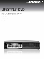
Bose Lifestyle® 48 Series IV DVD home entertainment system User manual
- Type
- User manual
Page is loading ...

2
Dansk Italiano SvenskaDeutsch NederlandsEnglish FrançaisEspañol SvenskaDeutsch Nederlands EnglishEspañol
SAFETY INFORMATION
Please read this guide
Please take the time to follow the instructions in this guide carefully. It will help you set up and operate your system
properly and enjoy all of its advanced features. Please save this guide for future reference.
Additional safety information
See the additional instructions on the Important Safety Information sheet enclosed in the shipping carton.
WARNINGS:
• To reduce the risk of fire or electrical shock, do not expose the product to rain or moisture.
• The apparatus shall not be exposed to dripping or splashing, and objects filled with liquids, such as vases, shall not
be placed on the apparatus. As with any electronic products, use care not to spill liquids into any part of the system.
Liquids can cause a failure and/or a fire hazard.
• No naked flame sources, such as lighted candles, should be placed on the apparatus.
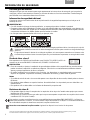
The lightning flash with arrowhead symbol within an equilateral triangle alerts the user to the presence of
uninsulated, dangerous voltage within the system enclosure that may be of sufficient magnitude to
constitute a risk of electrical shock.
The exclamation point within an equilateral triangle, as marked on the system, is intended to alert the user
to the presence of important operating and maintenance instructions in this owner’s guide.
Class 1 laser product
This CD/DVD player is classified as a CLASS 1 LASER PRODUCT according to
EN 60825-1:1994+A1+A2, IEC60825-1:1993+A1+A2.
CAUTIONS:
• Use of controls or adjustments or performance of procedures other than those specified herein may result in
hazardous radiation exposure. The compact disc player should not be adjusted or repaired by anyone except
properly qualified service personnel.
• Make no modifications to the system or accessories. Unauthorized alterations may compromise safety,
regulatory compliance, and system performance, and may void the warranty.
Notes:
• Where the mains plug or appliance coupler is used as the disconnect device, such disconnect device shall remain
readily operable.
• The product must be used indoors. It is neither designed nor tested for use outdoors, in recreation vehicles, or on
boats.
• This product is intended to be used only with the power supply provided.
Class B emissions
• This Class B digital apparatus meets all requirements of the Canadian Interference-Causing Equipment
Regulations (Canada only).
• If applicable, the radio communication device incorporated into this apparatus meets all requirements of the
Industry Canada standard RSS-310 (Canada only).
This product conforms to the EMC Directive 89/336/EEC and to the Low Voltage Directive
73/23/EEC. The remote control conforms to the RTTE Directive 99/5/EC. The complete
Declaration of Conformity can be found at www.Bose.com/static/compliance/index.html.
Please dispose of used batteries properly, following any local regulations. Do not incinerate.
CLASS 1 LASER PRODUCT
KLASSE 1 LASER PRODUKT
LUOKAN 1 LASER LAITE
KLASS 1 LASER APPARAT
©2007 Bose Corporation. No part of this work may be reproduced, modified, distributed, or otherwise used without prior written permission.
For additional copyright, trademark, patent, and licensing information, please refer to pages at the back of this book.

3
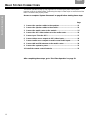
CONTENTS
Italiano SvenskaDeutsch NederlandsEnglish FrançaisEspañol
INTRODUCTION 5
Welcome . . . . . . . . . . . . . . . . . . . . . . . . . . . . . . . . . . . . . . . . . . . . . . . . . . . . . . . . . . . . . . . . . . . . . . . . . . . . . . . . . . . 5
Purpose of this guide . . . . . . . . . . . . . . . . . . . . . . . . . . . . . . . . . . . . . . . . . . . . . . . . . . . . . . . . . . . . . . . . . . . . . . . . . . 5
Additional setup help . . . . . . . . . . . . . . . . . . . . . . . . . . . . . . . . . . . . . . . . . . . . . . . . . . . . . . . . . . . . . . . . . . . . . . . . . . 5
Unpacking the carton . . . . . . . . . . . . . . . . . . . . . . . . . . . . . . . . . . . . . . . . . . . . . . . . . . . . . . . . . . . . . . . . . . . . . . . . . . 6
SYSTEM PLACEMENT 8
Placement guidelines . . . . . . . . . . . . . . . . . . . . . . . . . . . . . . . . . . . . . . . . . . . . . . . . . . . . . . . . . . . . . . . . . . . . . . . . . . 8
Media center placement . . . . . . . . . . . . . . . . . . . . . . . . . . . . . . . . . . . . . . . . . . . . . . . . . . . . . . . . . . . . . . . . . . . . 8
VS-2 video enhancer . . . . . . . . . . . . . . . . . . . . . . . . . . . . . . . . . . . . . . . . . . . . . . . . . . . . . . . . . . . . . . . . . . . . . . . 8
Front and rear speaker placement . . . . . . . . . . . . . . . . . . . . . . . . . . . . . . . . . . . . . . . . . . . . . . . . . . . . . . . . . . . . 9
Acoustimass
®
module placement . . . . . . . . . . . . . . . . . . . . . . . . . . . . . . . . . . . . . . . . . . . . . . . . . . . . . . . . . . . . . 10
Hearing the results of proper placement . . . . . . . . . . . . . . . . . . . . . . . . . . . . . . . . . . . . . . . . . . . . . . . . . . . . . . . . . . . 11
BASIC SYSTEM CONNECTIONS 12
1 Connect the speaker cables to the speakers . . . . . . . . . . . . . . . . . . . . . . . . . . . . . . . . . . . . . . . . . . . . . . . . . . . . 13
2 Connect the speaker cables to the module . . . . . . . . . . . . . . . . . . . . . . . . . . . . . . . . . . . . . . . . . . . . . . . . . . . . . . 14
3 Connect the media center to the module . . . . . . . . . . . . . . . . . . . . . . . . . . . . . . . . . . . . . . . . . . . . . . . . . . . . . . . 15
4 Connect the VS-2 video enhancer to the media center . . . . . . . . . . . . . . . . . . . . . . . . . . . . . . . . . . . . . . . . . . . . 16
5 Connect your TV to the VS-2 . . . . . . . . . . . . . . . . . . . . . . . . . . . . . . . . . . . . . . . . . . . . . . . . . . . . . . . . . . . . . . . . . 17
6 Connect video source outputs to VS-2 video inputs . . . . . . . . . . . . . . . . . . . . . . . . . . . . . . . . . . . . . . . . . . . . . . . 18
7 Connect audio source outputs to media center audio inputs . . . . . . . . . . . . . . . . . . . . . . . . . . . . . . . . . . . . . . . . 19
8 Connect AM and FM antennas to the media center . . . . . . . . . . . . . . . . . . . . . . . . . . . . . . . . . . . . . . . . . . . . . . . 20
9 Connect the system to power . . . . . . . . . . . . . . . . . . . . . . . . . . . . . . . . . . . . . . . . . . . . . . . . . . . . . . . . . . . . . . . . 21
10 Install the remote control batteries . . . . . . . . . . . . . . . . . . . . . . . . . . . . . . . . . . . . . . . . . . . . . . . . . . . . . . . . . . . . 22
FIRST-TIME OPERATION 23
1 Prepare your TV . . . . . . . . . . . . . . . . . . . . . . . . . . . . . . . . . . . . . . . . . . . . . . . . . . . . . . . . . . . . . . . . . . . . . . . . . . . 24
2 Open the ADAPTiQ
®
audio calibration system carton . . . . . . . . . . . . . . . . . . . . . . . . . . . . . . . . . . . . . . . . . . . . . . 24
3 Play Disc 1 . . . . . . . . . . . . . . . . . . . . . . . . . . . . . . . . . . . . . . . . . . . . . . . . . . . . . . . . . . . . . . . . . . . . . . . . . . . . . . . 25
4 Play Disc 2 – ADAPTiQ
®
audio calibration system . . . . . . . . . . . . . . . . . . . . . . . . . . . . . . . . . . . . . . . . . . . . . . . . 25
5 Disconnect the ADAPTiQ
®
headset. . . . . . . . . . . . . . . . . . . . . . . . . . . . . . . . . . . . . . . . . . . . . . . . . . . . . . . . . . . . 26
5
8
12
23
27
34
INTRODUCTION
SYSTEM PLACEMENT
BASIC SYSTEM CONNECTIONS
FIRST TIME OPERATION
OPTIONAL CONNECTIONS AND ADDITIONS
REFERENCE

4
SvenskaDeutsch Nederlands EnglishFrançaisEspañol
OPTIONAL CONNECTIONS AND ADDITIONS 27
Using digital audio connections . . . . . . . . . . . . . . . . . . . . . . . . . . . . . . . . . . . . . . . . . . . . . . . . . . . . . . . . . . . . . . . . . . 27
Making coaxial digital audio connections . . . . . . . . . . . . . . . . . . . . . . . . . . . . . . . . . . . . . . . . . . . . . . . . . . . . . . . 27
Making optical digital audio connections . . . . . . . . . . . . . . . . . . . . . . . . . . . . . . . . . . . . . . . . . . . . . . . . . . . . . . . 27
Activating an optical connection . . . . . . . . . . . . . . . . . . . . . . . . . . . . . . . . . . . . . . . . . . . . . . . . . . . . . . . . . . . . . . 27
Using the TV on/off sensor . . . . . . . . . . . . . . . . . . . . . . . . . . . . . . . . . . . . . . . . . . . . . . . . . . . . . . . . . . . . . . . . . . . . . 28
Using the IR emitter . . . . . . . . . . . . . . . . . . . . . . . . . . . . . . . . . . . . . . . . . . . . . . . . . . . . . . . . . . . . . . . . . . . . . . . . . . . 29
Using a remote control antenna extender . . . . . . . . . . . . . . . . . . . . . . . . . . . . . . . . . . . . . . . . . . . . . . . . . . . . . . . . . . 29
Using a SCART adapter . . . . . . . . . . . . . . . . . . . . . . . . . . . . . . . . . . . . . . . . . . . . . . . . . . . . . . . . . . . . . . . . . . . . . . . . 30
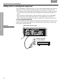
Making connections for program recording . . . . . . . . . . . . . . . . . . . . . . . . . . . . . . . . . . . . . . . . . . . . . . . . . . . . . . . . . 31
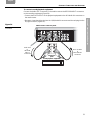
Adding audio record/playback equipment . . . . . . . . . . . . . . . . . . . . . . . . . . . . . . . . . . . . . . . . . . . . . . . . . . . . . . . . . . 32
REFERENCE 34
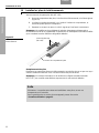
Mounting the VS-2 video enhancer . . . . . . . . . . . . . . . . . . . . . . . . . . . . . . . . . . . . . . . . . . . . . . . . . . . . . . . . . . . . . . . 34
Enjoying your system in other rooms . . . . . . . . . . . . . . . . . . . . . . . . . . . . . . . . . . . . . . . . . . . . . . . . . . . . . . . . . . . . . . 35
Adding other products . . . . . . . . . . . . . . . . . . . . . . . . . . . . . . . . . . . . . . . . . . . . . . . . . . . . . . . . . . . . . . . . . . . . . . 35
Making them all work together . . . . . . . . . . . . . . . . . . . . . . . . . . . . . . . . . . . . . . . . . . . . . . . . . . . . . . . . . . . . . . . 36
Accessories . . . . . . . . . . . . . . . . . . . . . . . . . . . . . . . . . . . . . . . . . . . . . . . . . . . . . . . . . . . . . . . . . . . . . . . . . . . . . . . . . 36
Contacting customer service . . . . . . . . . . . . . . . . . . . . . . . . . . . . . . . . . . . . . . . . . . . . . . . . . . . . . . . . . . . . . . . . . . . . 37
Limited warranty . . . . . . . . . . . . . . . . . . . . . . . . . . . . . . . . . . . . . . . . . . . . . . . . . . . . . . . . . . . . . . . . . . . . . . . . . . . . . . 37
Technical information . . . . . . . . . . . . . . . . . . . . . . . . . . . . . . . . . . . . . . . . . . . . . . . . . . . . . . . . . . . . . . . . . . . . . . . . . . 37
IMPORTANT! – Please register your product right away!
Registering your product entitles you to receive free system upgrades to keep your product performing optimally. It also
allows us to send you information about new products and special offers from Bose.
Follow the instructions on your Product Registration card to register by mail, on the Internet, or by phone. It’s quick and
easy! Failure to register will not affect your limited warranty rights.
For Your Records
Record your system serial numbers here and on your Product Registration Card. Serial numbers are located on the
bottom of the media center and the VS-2, and on the connection panel of the Acoustimass
®
module.
System model number (on the carton): LIFESTYLE _______ Series (if applicable) ______
Media center SN:__________________ VS-2 SN: ___________________ Acoustimass module SN: __________________
Dealer name:__________________________________ Dealer phone: ___________________Purchase date:______________
Bose recommends that you keep your sales receipt and a copy of your Product Registration card together with this guide.

5
Italiano SvenskaDeutsch NederlandsEnglish FrançaisEspañol
INTRODUCTION
INTRODUCTION
Welcome
Thank you for purchasing a Bose
®
LIFESTYLE
®
DVD home entertainment system with HDMI
TM
connectivity and automatic video switching. Through proprietary Bose technologies and
innovative LIFESTYLE
®
system design, this elegant and easy-to-use system delivers superior
performance for both music and video program content.
Your system features:
• HDMI connectivity
• Automatic video switching provided by the VS-2 video enhancer
• Proprietary ADAPTiQ
®
audio calibration system, which tailors system performance so it is
optimal in the location you choose
• Capability of expanding your system in up to 14 other rooms
Purpose of this guide
The detailed instructions in the following sections of this guide help you to set up your
system, connect everything together, and turn it on for the first time.
System Placement........................................ Explains how to place the parts of the
system in a room to create a home theater
atmosphere (page 8).
Basic System Connections......................... Shows how to connect the parts of the system
together using the included cables (page 12).
First-Time Operation.................................... Helps you turn on the system for the first time
and play the two included discs – one that
helps you check for correct cable connections
and another that performs a custom sound
calibration for the system (page 23).
Optional Connections and Additions........ Provides information on using alternate
connections and adding other equipment
to your system (page 27).
Additional setup help
If you need more help setting up your system, refer to:
• Quick Setup Guide – A visual guide that provides simple, graphic instructions in color.
• Online help – An interactive setup guide available at www.owners.Bose.com. This is
designed to help you with specific setup questions. At this time, the website is provided
in English only.
For specific questions or help in assessing a problem, be sure to contact Bose directly. Refer
to the contact list provided in the carton.

6
Dansk Italiano SvenskaDeutsch Nederlands EnglishFrançaisEspañol
INTRODUCTION
INTRODUCTION
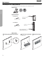
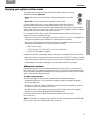
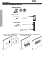
Unpacking the carton
Carefully unpack your system and save all of the packing materials, which provide the safest
means for shipping or transporting.
If any product part appears damaged, do not attempt to use it. Notify Bose or your authorized
Bose
®
dealer immediately. For Bose contact information, refer to the address sheet included
in the carton.
Note: Now is a good time to locate the serial numbers for your system, on the bottom of the
media center and VS-2, and near the connection panel on the Acoustimass
®
module. For future
reference, we suggest that you record those numbers in the space provided on page 4.
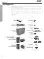
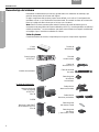
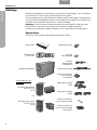
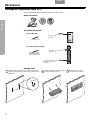
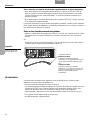
Parts list
As you unpack your system verify that you have the following parts.
Media
center
Power supply
LIFESTYLE
®
remote control
Remote control
batteries
Acoustimass
®
module
AC power
cords (2)
Audio input cable
Acoustimass
module
rubber feet
One set of 5 speakers
:
LIFESTYLE
®
28
or 38 system
double cube speakers
OR
Front speaker
cables
Rear speaker
cables
LIFESTYLE 35
or 48 system
Jewel Cube
®
speakers
Center speaker
rubber feet
Center Jewel Cube
®
speaker rubber feet
®
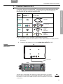
CD·DVDCD·DVD FM·AMFM·AM AUXAUX
CBL·SATCBL·SATTVTV VCRVCR
On
Off
ENTER
StoredStored
Mute
All
Mute
Volume
Rating
CD #
Similar
Playlist
Seek
Whole CD
Track
Chapter
Preset
Channel
Settings
System
Library
Exit
DVD Menu
Guide
uMusic
Shuffle
Repeat
Input
On
Off
On
Off
On
Off
StoredStored
123
456
78
0
9
Info Last
(4)
(1)
(4)
(1)

INTRODUCTION
7
Italiano SvenskaDeutsch NederlandsEnglish FrançaisEspañol
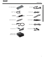
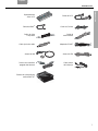
INTRODUCTION
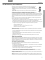
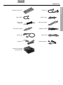
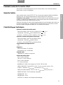
VS-2 video enhancer VS-2 cable
HDMI
TM
cable S-Video cable
Composite
video cable
Stereo audio cable
Optical audio cable SCART adapter
AM antenna FM antenna
TV on/off sensor IR emitter cable
ADAPTiQ
®
audio
calibration system

8
Dansk Italiano SvenskaDeutsch Nederlands EnglishFrançaisEspañol
SYSTEM PLACEMENT
SYSTEM PLACEMENT
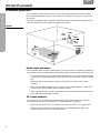
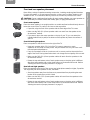
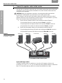
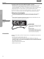
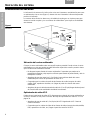
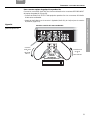
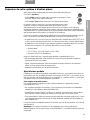
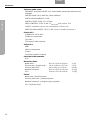
Placement guidelines
The information in this section shows you how to place your system in a room to create a
home theater atmosphere (Figure 1). You should try to arrange your system as close to this
as possible.
Placing your speakers and Acoustimass
®
module properly is the first step to getting the full,
rich Bose
®
quality sound this system is designed to provide.
Figure 1
System placement example
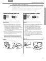
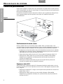
Media center placement
Place the media center on a flat, stable surface. Until your system is completely installed, it’s
a good idea to keep the media center positioned for easy access to its rear connection panel.
• Do not block the front of the media center. Make sure you can see the display window
on the right side and allow enough room to lift up the front door and open the CD/DVD
tray.
• Make sure there is space within 6 feet (1.8 m) behind it to place the VS-2 video
enhancer.
• Make sure the audio cables from your sound sources (cable/satellite box, DVR, VCR,
or other) can reach the media center connection panel.
• Make sure the 30 ft (9.1 m) audio input cable can reach from the media center connec-
tion panel to the Acoustimass module.
VS-2 video enhancer
You can place the VS-2 video enhancer directly behind the media center or on the floor,
or mount it on a wall. See “Mounting the VS-2 video enhancer” on page 34.
• Make sure the 6 ft (1.8 m) VS-2 cable can reach from the VS-2 to the media center.
• Make sure video cables from your video sources (cable/satellite box, DVR, VCR,
or other) can reach the VS-2 connection panel.
Left
front
Right
front
Center
Left
rear
Right
rear
Acoustimass
module

SYSTEM PLACEMENT
9
Italiano SvenskaDeutsch NederlandsEnglish FrançaisEspañol
SYSTEM PLACEMENT
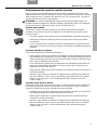
Front and rear speaker placement
Bose offers a variety of speaker mounting accessories, including stands and wall brackets.
For more information, or to purchase accessories, contact your local Bose
®
dealer or visit
www.Bose.com. To contact Bose directly, refer to the contact list provided in the carton.
CAUTION: Choose a stable and level surface for each speaker. Vibration can cause speakers to
move, particularly on smooth surfaces like marble, glass, or highly polished wood.
Front center speaker
Place the center speaker in an upright position on a stable and level surface directly above or
below the center of the TV screen or as close to that as possible.
• If possible, align the front of the speaker with the front edge of the TV screen.
• Make sure the 20 ft (6.1 m) front speaker cable can reach from the speaker to the
Acoustimass
®
module.
• If you want to place the center speaker on the top of your TV, you can attach the
supplied rubber feet (or pad) to the bottom of the speaker to protect the surface of
your TV.
Front left and right speakers
Place one speaker to the left and one to the right of the TV.
• Keep each speaker within 3 ft (1 m) of the TV screen to prevent too much
separation of the sound from the picture. Vary this distance to suit your room condi-
tions and personal preference.
• If any front speakers will be in a bookcase unit, be sure to position them at the front
edge of the shelf. Placing them farther back can change the tonal quality of the sound.
• Make sure the 20 ft (6.1 m) front speaker cables will reach from the speakers to the
Acoustimass module.
• Rotate the top and bottom cube of each speaker array so that they point in different
directions and toward a wall or other hard surface to create reflected sound. Refer to
“Hearing the results of proper placement” on page 11.
Rear left and right speakers
Place the speakers at the back of the room at ear height (when seated) or higher, if possible.
The longer the path from speakers to ears, the better.
• Aim the speakers away from the listeners to prevent them from pinpointing the exact
location of the sound source, which is ideal.
• Make sure the 50 ft (15.2 m) rear speaker cables will reach from the speakers to the
Acoustimass module.
• Rotate the top and bottom cube of each speaker array so that they point in different
directions and toward a wall or other hard surface to create reflected sound. Refer to
“Hearing the results of proper placement” on page 11.
OR
OR

10
Dansk Italiano SvenskaDeutsch Nederlands EnglishFrançaisEspañol
SYSTEM PLACEMENT
SYSTEM PLACEMENT
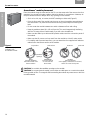
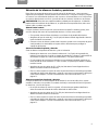
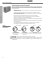
Acoustimass
®
module placement
Place the module along the same wall as the TV or at the same end of the room as the front
speakers. You can place it under a table or behind a cabinet, for convenience. However, do
not put it where furniture or drapes block any openings on the module.
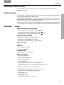
• Set it on its side, top, or bottom, but NOT standing on either end (Figure 2).
• Point the front end of the module into the room or place the module perpendicular to
the closest wall. This prevents the wall from blocking sound output or boosting the
bass.
• Do not center the module between two walls or between a floor and ceiling.
• Keep the module at least 18 in (45 cm) from the TV to avoid magnetically interfering
with the TV image. Move it farther away if you still notice interference.
• Make sure the audio input cable and all speaker cables reach the connection panel of
the module.
• Make sure the AC power cord can reach from the module to a live AC mains outlet.
• For stability and to protect bare floors, you can attach the four supplied self-adhesive
rubber feet to the bottom surface of the module.
Figure 2
Proper and improper
positioning of an
Acoustimass module
CAUTION: Do not block the ventilation openings on the module.
CAUTION: Do not put electronic media, such as video or audio tapes on or next to the module
for long periods of time. The magnetic field surrounding the module may erase some or all of the
recorded material.
BEST
For best ventilation,
stand the module on its
bottom surface.
ALTERNATE
Place the module
on one of its two
broad sides.
DO NOT
stand the module
on its slightly curved front or back end,
which can cause it to tip over.
Top surface
Side surface
Back end
Front end
Ventilation
openings

SYSTEM PLACEMENT
11
Italiano SvenskaDeutsch NederlandsEnglish FrançaisEspañol
SYSTEM PLACEMENT
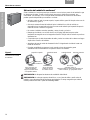
Hearing the results of proper placement
Properly placing the system speakers and Acoustimass
®
module leads to getting the full, rich
Bose
®
quality sound this system is designed to provide. The diagram in Figure 3 illustrates the
sound distribution you are attempting to achieve.
Figure 3
Results of proper speaker
placement
Note: If after placing the system you discover that you need additional cables, they are available
from your local Bose dealer. Or, to contact Bose directly, refer to the contact list provided in the
carton. If you prefer, you can order cables from our website: www.Bose.com.
Left front
(L)
Right front
(R)
Center
(C)
Acoustimass
®
module
Right rear (RR)
Left rear (LR)
Next
After placing the parts of the system in the best locations for your room, go to
“Basic System Connections” on page 12.

12
Dansk Italiano SvenskaDeutsch Nederlands EnglishFrançaisEspañol
BASIC SYSTEM CONNECTIONS
BASIC SYSTEM CONNECTIONS
This section provides a step-by-step approach to connecting the parts of the system
together using the included cables. Performing the steps in order helps to ensure that all the
basic connections are properly made.
Be sure to complete “System Placement” on page 8 before starting these steps:
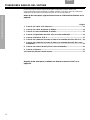
Page
1 Connect the speaker cables to the speakers...................................... 13
2 Connect the speaker cables to the module......................................... 14
3 Connect the media center to the module............................................ 15
4 Connect the VS-2 video enhancer to the media center....................... 16
5 Connect your TV to the VS-2 ............................................................... 17
6 Connect video source outputs to VS-2 video inputs............................ 18
7 Connect audio source outputs to media center audio inputs.............. 19
8 Connect AM and FM antennas to the media center ............................ 20
9 Connect the system to power.............................................................. 21
10 Install the remote control batteries..................................................... 22
After completing these steps, go to “First-Time Operation” on page 23.

BASIC SYSTEM CONNECTIONS
13
Italiano SvenskaDeutsch NederlandsEnglish FrançaisEspañol
BASIC SYSTEM CONNECTIONS
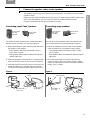
1 Connect the speaker cables to the speakers
The speakers you have are one of the two types shown here. They differ in how the cables
connect to them.
Before you start, route the cables around your room. To make the rear speaker cables reach
each of the rear speakers, you can unzip the cables by simply pulling them apart.
Follow the instructions for the type of speakers you have.
Connecting Jewel Cube
®
speakers
Connecting array speakers
The cables for these speakers have a customized plug
that fits into the connector only one way (Figure 4).
A. Notice the marking on each cable plug and match it to
the speaker in that location:
• Front speaker cable plugs are marked L (left), R
(right), and C (center).
• Rear speaker cable plugs are marked LR (left rear)
and RR (right rear).
B. Orient the plug with its small knob up, so the plug slips
easily into a notch on top of the connector (Figure 4).
C. Insert the plug fully into the connector on the rear of its
respective speaker. For example, the plug marked L
connects to the speaker at the left front of your room.
Figure 4
Jewel Cube speaker connections
The cables for these speakers have wire ends that con-
nect to red and white connection terminals (Figure 5).
A. Notice the marking on the red collar on the speaker
cable and match it to the speaker in that location:
• Front speaker cables are marked L (left), R (right),
and C (center).
• Rear speaker cables are marked LR (left rear) and RR
(right rear).
B. Press the terminal tab to insert each wire into the
proper connector. Be sure to match the red-collared
wire to the red speaker connection terminal to maintain
proper + and – polarity.
Figure 5
Array speaker connections
Front and rear
left, right
speakers
Front center
speaker
Front and rear
left, right
speakers
Front center
speaker
Knob
Plug label: R, L,
RR, or LR
Plug label: C
Terminal tab
Wire label: L, R,
LR, or RR
Wire label: C

14
Dansk Italiano SvenskaDeutsch Nederlands EnglishFrançaisEspañol
BASIC SYSTEM CONNECTIONS
BASIC SYSTEM CONNECTIONS
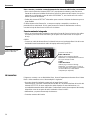
2 Connect the speaker cables to the module
You may find it convenient to temporarily turn the module upside down while making these
connections. Then, be sure to place the module on its side or bottom surface when the
connections are completed.
CAUTION: Before you make these connections, be sure that the media center and the
Acoustimass
®
module are NOT yet connected to an AC (mains) power outlet.
The RCA plugs on the free end of the speaker cables are colored to match the colored
speaker connectors on the Acoustimass connection panel. For a color reference, you may
want to use the Quick Setup Guide provided in the carton.
A. Connect the front speaker cables to the Acoustimass module (Figure 6):
• Plug the white front left (L) cable into the white Front L connector.
• Plug the light blue front right (R) cable into the light blue Front R connector.
• Plug the brown front center (C) cable into the brown Front C connector.
B. Connect the rear speaker cables to the Acoustimass module (Figure 6):
• Plug the light green left rear (LR) cable into the light green Rear LR connector.
• Plug the purple right rear (RR) cable into the purple Rear RR connector.
Figure 6
Speaker connections to the
Acoustimass
®
module
If you need longer cables:
To lengthen speaker cables, as needed, you can splice in 18-gauge or thicker cord
(connecting + to + and – to –). Or, you can order heavy-duty speaker extension cables from
Bose. To contact Bose directly, refer to the contact list provided in the carton.
Right Rear Right Front Center Front Left Front Left Rear
C
RR
Acoustimass module connector panel
R
L
LR

BASIC SYSTEM CONNECTIONS
15
Italiano SvenskaDeutsch NederlandsEnglish FrançaisEspañol
BASIC SYSTEM CONNECTIONS
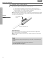
3 Connect the media center to the module
Use the audio input cable, which has a multi-pin connector at each end, to connect the
Acoustimass
®
module to the media center.
A. With the flat side of the multi-pin connector facing toward the front of the module,
plug one end of the audio input cable into the Media Center connector on the
Acoustimass module connection panel (Figure 7).
B. Plug the other end of the cable (flat side of plug facing up) into the Main Speakers
connector on the media center connection panel.
C. Make sure that each connector is fully inserted into the jack.
Figure 7
Acoustimass connection
to the media center
CAUTION: Do not put strain on the audio input cable where it connects to the module and
media center. Excessive strain, caused by pulling directly on the cable or by compressing it, can
cause damage.
Audio input cable
Media center
connection panel
Acoustimass module
connection panel
Flat side up
Main Speakers
connector
Media Center
connector
Flat side
toward front
of module

16
Dansk Italiano SvenskaDeutsch Nederlands EnglishFrançaisEspañol
BASIC SYSTEM CONNECTIONS
BASIC SYSTEM CONNECTIONS
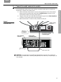
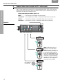
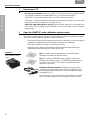
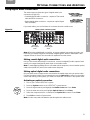
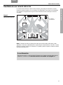
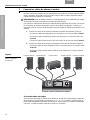
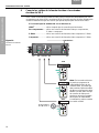
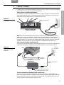
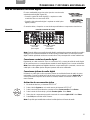
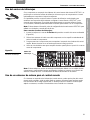
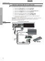
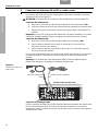
4 Connect the VS-2 video enhancer to the media center
To complete this connection, you need the power supply and the VS-2 cable.
A. Insert the Serial Data plug into the Serial Data connector.
B. Insert the DC Power plug into the DC Power connector.
C. Insert the Composite plug into the Composite Video OUT connector.
D. Insert the S-Video plug into the S-Video OUT connector.
E. Insert multi-pin plug into the Media Center connector.
F. Insert the DC Power plug into the DC POWER Out connector.
G. Insert the DC power cord from the power supply into the DC POWER In connector on
the VS-2.
Note: Straighten the DC power cord from the power supply to the VS-2 and from the VS-2 to
the media center as much as possible. This cord is used as the antenna for your LIFESTYLE
®
system remote control.
Figure 8
VS-2 connections to the
media center
VS-2
cable
VS-2 end panel
Power supply
Media center rear panel
VS-2 video
expander
A
G
DC power cord
B
C
D
E
F

BASIC SYSTEM CONNECTIONS
17
Italiano SvenskaDeutsch NederlandsEnglish FrançaisEspañol
BASIC SYSTEM CONNECTIONS
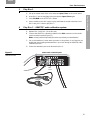
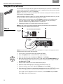
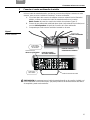
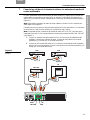
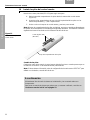
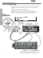
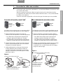
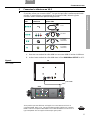
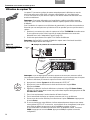
5 Connect your TV to the VS-2
If possible, use an HDMI
TM
connection. This provides the highest video image quality. If your
TV does not have an HDMI connector, use the type of connection that gives you the highest
image quality possible.
Connect your TV to the VS-2 using the supplied HDMI cable:
A. Plug one end of the HDMI cable into the HDMI connector on the rear of your TV.
B. Plug the other end into the HDMI Video OUTPUT connector on the VS-2.
Figure 9
TV HDMI connection to the
VS-2
Video
Quality
TV Input Video
Connector Cable Type
Best HDMI*
Better Component
Good S-Video
Standard Composite
Supplied
Not supplied
Supplied
with your
LIFESTYLE
®
system
Supplied
with your
LIFESTYLE
®
system
TV
VS-2
HDMI cable
*Instead of an HDMI connector, your TV may have a DVI connector. In this case, you still
can use an HDMI connection by using a DVI-to-HDMI cable adapter or a DVI-to-HDMI
cable. You can find this adapter at your local electronics dealer.
DVI

18
Dansk Italiano SvenskaDeutsch Nederlands EnglishFrançaisEspañol
BASIC SYSTEM CONNECTIONS
BASIC SYSTEM CONNECTIONS
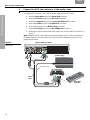
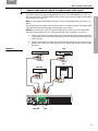
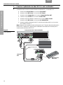
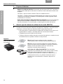
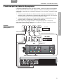
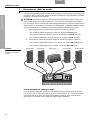
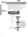
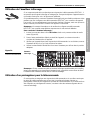
6 Connect video source outputs to VS-2 video inputs
The VS-2 has video input connectors for a cable/satellite box (CBL-SAT), a VCR, and one
other source (AUX). The type of video connection used for your TV determines the type of
connection you can use for a video source:
If the connection you made to your TV is:
HDMI
TM
............use any type of connection for your sources.
Component....use a component, S-Video, or composite video source connection.
S-Video...........use either an S-Video or composite video source connection.
Composite .....use either an S-Video or composite video source connection.
Figure 10
VS-2 input connections
To TV
VCR
CBL•SAT
AUX
VCRCBL
•
SATAUX
Not available on
VS-2 AUX IN
Note: If after turning on your
system you can’t view cable/
satellite programs through an
HDMI connection, you may need
to change the video output set-
ting in your cable/satellite box. To
do this, use another type of video
connection so you can view the
onscreen menu from your cable/
satellite box. Then change the
connection back to HDMI.

BASIC SYSTEM CONNECTIONS
19
Italiano SvenskaDeutsch NederlandsEnglish FrançaisEspañol
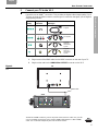
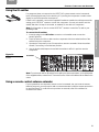
BASIC SYSTEM CONNECTIONS
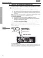
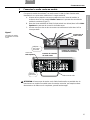
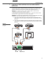
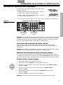
7 Connect audio source outputs to media center audio inputs
The media center has analog and digital audio inputs for your cable/satellite box, VCR, TV,
and one other source. This step explains how to connect your sources using the analog audio
input connections (Figure 11).
Note: To make higher-quality audio connections, refer to “Using digital audio connections” on
page 27.
You need an RCA stereo audio cable for each source to complete this step. One stereo audio
cable with red and white RCA plugs is supplied with your system.
Note: Make sure the VCR, CBL-SAT, and AUX audio input connections on the media center
match the corresponding VCR, CBL-SAT, and AUX video input connections on the VS-2.
A. Plug one end of an RCA stereo cable into the left and right audio output connectors
on the audio source. Match the white plug to the left (L) output and the red plug to the
right (R) output.
B. Plug the other end of the cable into the left and right audio input connectors on the
media center. Match the white plug to the left (L) output and the red plug to the right
(R) output.
Figure 11
Analog audio connections
AUX
CBL-SAT VCR
TV
CBL•SAT
VCR
AUX
TV

20
Dansk Italiano SvenskaDeutsch Nederlands EnglishFrançaisEspañol
BASIC SYSTEM CONNECTIONS
BASIC SYSTEM CONNECTIONS
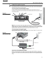
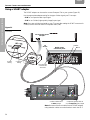
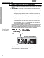
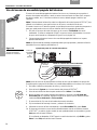
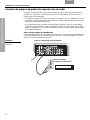
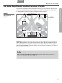
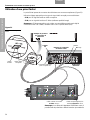
8 Connect AM and FM antennas to the media center
The supplied AM and FM antennas connect to the rear panel of the media center (Figure 12).
CAUTION: DO NOT connect your television antenna cable to the FM antenna jack.
To connect the FM antenna
A. Insert the plug on the FM dipole antenna lead into the FM antenna connector.
B. Place the antenna as far from the media center and other components as possible.
C. Spread out the antenna arms and change their orientation as needed to get the best
FM reception.
Note: The FM jack (75 ohm) may be used with an outdoor antenna. Before doing this, consult a
qualified installer. Follow all safety instructions supplied with the antenna.
To connect the AM antenna
A. Insert the plug on the AM antenna lead into the AM antenna connector.
B. Stand the loop antenna on the base or mount the antenna on a wall, following the
instructions enclosed with the AM antenna.
C. Move the AM loop antenna at least 20 in (50 cm) from the media center and at least 2
ft (60 cm) from the Acoustimass
®
module.
When all connections are completed and you can turn on your system, you may need to
experiment with the orientation of the loop antenna for optimum AM reception.
Note: AM reception can be adversely affected by a nearby television when it is on. Turn off the
TV for best AM reception.
Figure 12
Media center antenna
connections
To connect to cable radio
Some cable TV providers make FM radio signals available through the cable service to your
home. Using a signal splitter, you may be able to feed the cable radio signals to the FM con-
nector on your media center. Contact your cable TV provider for assistance.
FM dipole antenna lead
AM antenna lead
Media center rear panel

BASIC SYSTEM CONNECTIONS
21
Italiano SvenskaDeutsch NederlandsEnglish FrançaisEspañol
BASIC SYSTEM CONNECTIONS
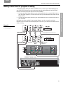
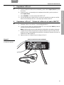
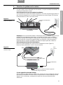
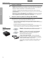
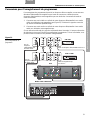
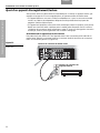
9 Connect the system to power
To complete this step, you need the two identical AC power cords, one for the Acoustimass
®
module and the other for the power supply.
To connect power to the Acoustimass module:
On the connector panel of the Acoustimass module, plug the appropriate end of one
AC power cord into the AC power jack (Figure 13). Insert the other end of the power cord into
an AC (mains) outlet.
Figure 13
Power connection for
the Acoustimass module
Note: Bose recommends using a high-quality surge suppressor on all electronics equipment.
Voltage variations and spikes can damage electronic components in any system and the resulting
damage may not be covered by the limited warranty. A quality suppressor can eliminate the vast
majority of failures attributed to surges and may be purchased at electronics stores.
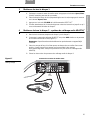
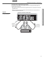
To connect power to the power supply:
Plug the appropriate end of the AC power cord into power supply (Figure 13). Insert the other
end of the power cord into an AC (mains) outlet.
Figure 14
Power connection for the
media center power supply
If you have a dual-voltage power supply:
Before connecting power to the media center power supply, MAKE SURE the voltage selec-
tion switch on the bottom of the media center power supply matches the local power rating
(Figure 14). Check with local electrical authorities if you are not sure of the appropriate power
rating.
AC (mains)
outlet
AC power jack
AC power cord
Acoustimass module
connection panel
AC Power cord
Voltage selection switch location
(dual-voltage units only)
Power supply
AC (mains)
outlet
VS-2
To the
media center
Page is loading ...
Page is loading ...
Page is loading ...
Page is loading ...
Page is loading ...
Page is loading ...
Page is loading ...
Page is loading ...
Page is loading ...
Page is loading ...
Page is loading ...
Page is loading ...
Page is loading ...
Page is loading ...
Page is loading ...
Page is loading ...
Page is loading ...
Page is loading ...
Page is loading ...
Page is loading ...
Page is loading ...
Page is loading ...
Page is loading ...
Page is loading ...
Page is loading ...
Page is loading ...
Page is loading ...
Page is loading ...
Page is loading ...
Page is loading ...
Page is loading ...
Page is loading ...
Page is loading ...
Page is loading ...
Page is loading ...
Page is loading ...
Page is loading ...
Page is loading ...
Page is loading ...
Page is loading ...
Page is loading ...
Page is loading ...
Page is loading ...
Page is loading ...
Page is loading ...
Page is loading ...
Page is loading ...
Page is loading ...
Page is loading ...
Page is loading ...
Page is loading ...
Page is loading ...
Page is loading ...
Page is loading ...
Page is loading ...
Page is loading ...
Page is loading ...
Page is loading ...
Page is loading ...
Page is loading ...
Page is loading ...
Page is loading ...
Page is loading ...
Page is loading ...
Page is loading ...
Page is loading ...
Page is loading ...
Page is loading ...
Page is loading ...
Page is loading ...
Page is loading ...
Page is loading ...
Page is loading ...
Page is loading ...
Page is loading ...
Page is loading ...
Page is loading ...
Page is loading ...
Page is loading ...
Page is loading ...
Page is loading ...
Page is loading ...
Page is loading ...
Page is loading ...
Page is loading ...
Page is loading ...
Page is loading ...
Page is loading ...
Page is loading ...
Page is loading ...
Page is loading ...
Page is loading ...
-
 1
1
-
 2
2
-
 3
3
-
 4
4
-
 5
5
-
 6
6
-
 7
7
-
 8
8
-
 9
9
-
 10
10
-
 11
11
-
 12
12
-
 13
13
-
 14
14
-
 15
15
-
 16
16
-
 17
17
-
 18
18
-
 19
19
-
 20
20
-
 21
21
-
 22
22
-
 23
23
-
 24
24
-
 25
25
-
 26
26
-
 27
27
-
 28
28
-
 29
29
-
 30
30
-
 31
31
-
 32
32
-
 33
33
-
 34
34
-
 35
35
-
 36
36
-
 37
37
-
 38
38
-
 39
39
-
 40
40
-
 41
41
-
 42
42
-
 43
43
-
 44
44
-
 45
45
-
 46
46
-
 47
47
-
 48
48
-
 49
49
-
 50
50
-
 51
51
-
 52
52
-
 53
53
-
 54
54
-
 55
55
-
 56
56
-
 57
57
-
 58
58
-
 59
59
-
 60
60
-
 61
61
-
 62
62
-
 63
63
-
 64
64
-
 65
65
-
 66
66
-
 67
67
-
 68
68
-
 69
69
-
 70
70
-
 71
71
-
 72
72
-
 73
73
-
 74
74
-
 75
75
-
 76
76
-
 77
77
-
 78
78
-
 79
79
-
 80
80
-
 81
81
-
 82
82
-
 83
83
-
 84
84
-
 85
85
-
 86
86
-
 87
87
-
 88
88
-
 89
89
-
 90
90
-
 91
91
-
 92
92
-
 93
93
-
 94
94
-
 95
95
-
 96
96
-
 97
97
-
 98
98
-
 99
99
-
 100
100
-
 101
101
-
 102
102
-
 103
103
-
 104
104
-
 105
105
-
 106
106
-
 107
107
-
 108
108
-
 109
109
-
 110
110
-
 111
111
-
 112
112
-
 113
113


Bose Lifestyle® 48 Series IV DVD home entertainment system User manual
- Type
- User manual
Ask a question and I''ll find the answer in the document
Finding information in a document is now easier with AI
in other languages
Related papers
-
Bose Professional Lifestyle® 18 Series III Installation guide
-
Bose Lifestyle (R) VS-2 User manual
-
Daewoo MediaMate® computer speakers User manual
-
-
-
Bose 3-2-1 system Owner's manual
-
-
 Bose® 535 User manual
-
Bose® MediaMate® computer speakers User manual
-

Other documents
-
Philips 42pf7321D/37 Quick start guide
-
Swann 4480 Hardware Installation Manual
-
iON Video 2 SD Quick start guide
-
Hama 00040972 Owner's manual
-
Sony DMX-NV1 Owner's manual
-
Philips 37PFL7332D/37 Quick start guide
-
-
-
Dali Sound Hub User guide
-
Sony BDV-E780W Quick setup guide