SoundStation IP 6000

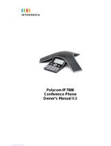
Polycom SoundStation IP 6000, Conference Phone, SoundStation IP 5000 Owner's manual

  • Hello! I am an AI chatbot trained to assist you with the Polycom SoundStation IP 6000 Owner's manual. I’ve already reviewed the document and can help you find the information you need or explain it in simple terms. Just ask your questions, and providing more details will help me assist you more effectively!
Owner’s Manual
Polycom Conference Phone V.1
ACC 1038- PUG
Table of Contents
1! Introduction ........................................................................ 5!
Conformance ........................................................................ 5!
Important Safety instructions ................................................ 5!
FCC Information ................................................................... 7!
Using this Document .......................................................... 10!
Basic Requirements ........................................................... 10!
2! Getting to know your Hosted PBX system ..................... 12!
Before you Begin Your Installation ..................................... 12!
Assigning Extension Numbers and Phone
Numbers to Phones ........................................................ 13!
! Installing your Polycom Conference Phone ................... 14!
3 ........................................................................................................ 14!
Installing your Conference Phone ...................................... 14!
Activating the Service ......................................................... 17!
2.! Using Your Hosted PBX phone system ......................... 17!
System Description ............................................................. 17!
Getting Started .................................................................... 18!
Conference Phone ............................................................. 18!
Introduction to your Polycom Conference
Phone ....................................................................... 18!
Conference Phone Basic Call Features .......................... 22!
Answering Calls ........................................................... 22!
Handling Multiple Calls ................................................ 22!
Answering When in another Call ................................ 22!
Placing Calls ................................................................ 25!
Placing a Second Call ................................................. 26!
Call Hold ....................................................................... 28!
Call Transfer ................................................................ 28!
Call Park ....................................................................... 31!
Paging (Intercom) ........................................................ 31!
Forwarding Incoming Calls .......................................... 32!
Conference Calls ......................................................... 35!
Using Voicemail .................................................................. 38!
Setting up the voicemail box for the first time ............. 38!
Retrieving messages from your Conference
Phone ....................................................................... 38!
Retrieving messages when you are away from
the office ................................................................... 39!
Returning a Call ........................................................... 39!
Change your Voicemail PIN ........................................ 39!
Record a Personal Greeting via the Phone ................ 40!
Forward Voicemail Messages via the Phone ............. 40!
Logging into your Voicemail Box via the Web ............ 40!
Retrieving messages via the Web .............................. 41!
Forward Voicemail Messages via the Web ................ 41!
To Create a Voicemail Group ..................................... 44!
Change the Amount of Time Before Voicemail
Picks Up ................................................................... 45!
Additional Call Features ..................................................... 46!
Using Call Lists ............................................................ 46!
Managing Call Lists ..................................................... 47!
Speed Dial list .............................................................. 48!
Managing Contacts ..................................................... 49!
Inbound Caller ID ......................................................... 55!
Extension Set-Up options ................................................... 56!
Do Not Disturb ............................................................. 56!
Configuring Basic Setting ................................................... 57!
4! Administrator Functions .................................................. 64!
Making Changes through the Web-based Admin
Portal ............................................................................... 64!
Logging In .................................................................... 65!
Viewing a List of your Phone Numbers and
Extensions ................................................................ 66!
Moving a Stand Alone Phone ..................................... 67!
Moving a Shared Line Phone ...................................... 68!
Changing the Extension Number of a Phone ............. 69!
Changing the Display Name of a Phone .................... 70!
Changing the Time Zone of a Phone .......................... 70!
Changing the Outbound Caller ID of a Phone ............ 71!
Changing the Failover Routing of a Phone ................ 73!
Viewing Call History for a Phone ................................ 73!
Admin Portal Additional Features: .............................. 74!
1 Introduction
Congratulations on purchasing the AccessLine Hosted PBX phone
system and service. DPS FLEX twas designed specifically for the
small to mid-size business and combines a business-class phone
system with Voice over IP phone service.
This User Guide will show you how to setup and use your new DPS
FLEX phone system and service.
IMPORTANT SAFETY AND CONFORMANCE
INFORMATION FOR IP PBX BASE UNIT AND
PHONES
Conformance
This equipment is designed for use in the United States.
This equipment complies with the following standards:
FCC Part 15, Subparts B, C, D
FCC Part 68
UL60950
Analog extension ports: TNV3
CO port: TNV3
ADSL port: TNV3
Power fail port TNV3
LAN/WAN ports SELV
Important Safety instructions
The following safety information is reprinted from IEC60950.
When using your telephone equipment, basic safety
precautions should always be followed to reduce the risk of fire,
electric shock, and injury to persons, including the following:
Read and understand all instructions.
Follow all warnings and instructions marked on the product.
Unplug this product from the wall outlet before cleaning. Do not
use liquid cleaners or aerosol cleaners. Use a damp cloth for
cleaning.
Do not use this product near water (for example, in a wet
basement).
Do not place this product on an unstable cart, stand, or table.
The product can fall, causing serious damage to the product.
Slots and openings in the cabinet and the back or bottom are
provided for ventilation, to protect it from overheating; these
openings must not be blocked or covered. This product should
never be placed near or over a radiator or heat register. This
product should not be placed in a built-in installation unless
proper ventilation is provided.
This product should be operated only from the type of power
source indicated in the manual. If you are not sure of the type of
power source to your building, consult your dealer or local
Power Company.
The power socket outlet must be located near the product and
must be easily accessible to allow plugging/unplugging.
Do not allow anything to rest on the power cord. Do not locate
this product where persons walking on it will abuse the cord.
Do not use an extension cord with this product’s AC power
cord. The AC outlet for this product should not be used for any
other electrical equipment.
Never push objects of any kind into this product through cabinet
slots as they can touch dangerous voltage points or short out
parts that could result in a risk of fire or electric shock. Never
spill liquid of any kind on the product.
To reduce the risk of electric shock, do not disassemble this
product, but take it to a qualified serviceman when some
service or repair work is required. Opening or removing covers
can expose you to dangerous voltages or other risks. Incorrect
re-assembly can cause electric shock when the product is
subsequently used.
Unplug this product from the wall outlet and refer servicing to
qualified service personnel under the following conditions:
- When the power supply cord or plug is damaged or frayed.
- If liquid has been spilled into the product.
- If the product has been exposed to rain or water.
- If the product does not operate normally by following the
operating instructions.
- Adjust only those controls that are covered by the operating
instructions because improper adjustment of other controls can
result in damage and will often require extensive work by a
qualified technician to restore the product to normal operation.
- If the product has been dropped or the cabinet has been
damaged.
- If the product exhibits a distinct change in performance.
Avoid using a telephone during an electrical storm. There can
be a remote risk of electric shock from lightning.
Do not use the telephone to report a gas leak in the vicinity of
the leak.
CAUTION
Use only 26 AWG line cord or larger for
Central Office line connections.
FCC Information
Customer Owned Coin/Credit Card Phones
To comply with state tariffs, the Telephone Company must be given
notification prior to connection. In some states, the state public utility
commission, public service commission or corporation commission
must give prior approval of connection.
Data Equipment
The table below shows which jacks are associated with which
modes of operation:
Mode of Operation
USOC Jack
Permissive
RJ11C
Systems
Facility Interface Codes (FIC), Service Order Codes (SOC), USOC
Jack Codes and Ringer Equivalence Numbers (REN) are shown in
the table below for each port where applicable:
Port
FIC
SOC
USOC
REN
Line 1
02LS2
9.0Y
RJ11C
0.1B
Line 2
02LS2
9.0Y
RJ11C
0.1B
Line 3
02LS2
9.0Y
RJ11C
0.1B
Phone
02LS2
9.0Y
RJ11C
0.1B
Automatic Dialers
WHEN PROGRAMMING EMERGENCY NUMBERS AND (OR)
MAKING TEST CALLS TO EMERGENCY NUMBERS:
1. Remain on the line and briefly explain to the dispatcher the
reason for the call.
2. Perform such activities in the off-peak hours, such as early
morning or late evenings.
Toll Restriction and Least Cost Routing Equipment
The software contained in DPS FLEX phone system to allow user
access to the network must be upgraded to recognize newly
established network area codes and exchange codes as they are
placed into service.
Failure to upgrade the premises systems or peripheral equipment to
recognize the new codes as they are established will restrict the
customer and the customer's employees from gaining access to the
network and to these codes.
Equal Access Requirements
This equipment is capable of providing users access to interstate
providers of operator services through the use of access codes.
Modification of this equipment by call aggregators to block access
dialing codes is a violation of the Telephone Operator Consumers
Act of 1990.
Electrical Safety Advisory
It is strongly suggested that an AC surge arrestor be installed in the
AC outlet to which this equipment is connected.
Radio Interference
This device complies with Part 15 of the FCC Rules. Operation is
subject to the following two conditions: (1) this device may not
cause harmful interference, and (2) this device must accept any
interference received, including interference that may cause
undesired operation.
This equipment has been tested and found to comply with the limits
for a Class B digital device, pursuant to Part 15 of the FCC Rules.
These limits are designed to provide reasonable protection against
harmful interference in a residential installation. This equipment
generates uses and can radiate radio frequency energy and, if not
installed and used in accordance with the instructions, may cause
harmful interference to radio communications. However, there is no
guarantee that interference will not occur in a particular installation.
If this equipment does cause harmful interference to radio or
television reception, which can be determined by turning the
equipment off and on, the user is encouraged to try to correct the
interference by one or more of the following measures:
Reorient or relocate the receiving antenna.
Increase the separation between the equipment and receiver.
Connect the equipment into an outlet on a circuit different from
that to which the receiver is connected.
Consult the dealer or an experienced radio/TV technician for
help.
RF Radiation Exposure
This equipment complies with FCC radiation exposure limits set
forth for an uncontrolled environment. This equipment should be
installed and operated with a minimum distance of 8 inches (20
centimeters) between the radiator and your body.
This transmitter must not be co-located or operated in conjunction
with any other antenna or transmitter.
Modifications
Changes or modifications not expressly approved by the party
responsible for compliance could void the user's authority to operate
the equipment. There are no user-serviceable parts or adjustments
inside this equipment - please do not open the equipment case.
IMPORTANT SAFETY AND CONFORMANCE
INFORMATION FOR VERTICAL CORDLESS
TRANSMITTER AND CORDLESS PHONES
FCC Information
Part 15 FCC Rules
This device is compliant with Part 15 of the FCC Rules.
Operation is subject to the following two conditions:
1. This device may not cause harmful interference, and
2. This device must accept any interferences received, including
interference that may cause undesired operation.
Class B Digital Device or Peripheral
Note: This equipment is tested and complies with the limits for a
Class B digital device, pursuant to Part 15 of the FCC Rules.
These limits are designed to provide reasonable protection
against harmful interference in a residential installation. This
equipment generates, uses, and can radiate radio frequency
energy and, if not installed and used in accordance with the
instructions, may cause harmful interference to radio
communications. However, there is no guarantee that
interference will not occur in a particular installation. If this
equipment does cause harmful interference to radio or television
reception, which can be determined by turning the equipment off
and on, the user is encouraged to try to correct the interference
by one or more of the following measures:
1. Reorient or relocate the receiving antenna.
2. Increase the separation between the equipment and receiver.
3. Connect the equipment into an outlet on a circuit different from
that to which the receiver is connected.
4. Consult the dealer or an experienced radio/TV technician for
help.
Modifications
In accordance with Part 15 of the FCC Rules, the user is
cautioned that any changes or modifications not expressly
approved by Polycom, Inc. could void the user’s authority to
operate the equipment. This equipment may not be used on a
coin service or party line.
Installation Instructions
Installation must be performed in accordance with all relevant
national wiring rules.
When using Power over Ethernet (PoE), the equipment is to be
connected only to PoE networks without connections to the
outside plant.
Plugs Acts as Disconnect Device
The socket outlet to which this apparatus is connected must be
installed near the equipment and must always be readily
accessible.
Industry Canada (IC)
This Class [B] digital apparatus complies with Canadian ICES-
003.
Cet appareil numérique de la classe [B] est conforme à la norme
NMB-003 du Canada.
CE and VCCI Mark
This SoundStation IP 6000 phone is marked with the CE mark.
This mark indicates compliance with EC Directives 2006/95/ED
and 2004/108/EC. A full copy of the Declaration of Conformity
can be obtained from Polycom Ltd., 270 Bath Road, Slough,
Berkshire, SL1 4DX, UK.
Using this Document
Notational conventions
Acronyms are defined the first time they appear in the text.
The term LAN refers to a group of Ethernet-connected computers at
one site.
Typographical conventions
Italic text is used for items you select from menus and drop-down
lists and the names of displayed web pages.
Bold text is used for text strings that you type when prompted by the
program, and to emphasize important points.
Special messages
This document uses the following icons to draw your attention to
specific instructions or explanations.
Note
Provides clarifying or non-essential information on the current
topic.
Definition
Explains terms or acronyms that may be unfamiliar to many
readers. These terms are also included in the Glossary.
WARNING
Provides messages of high importance, including messages
relating to personal safety or system integrity.
Basic Requirements
The DPS FLEX phone system is designed to use your existing
broadband data connection as well as the existing data wiring in
your office. Where you don’t have data wiring, you may use the
optional Wireless Adapters to connect Conference Phones to the
optional Base Unit wirelessly.
In order to use all the features of the DPS FLEX phone system and
service, you must have the following:
Broadband Internet access
At least one free port on your router or modem/router
Your router must be set to DHCP
2 Getting to know your Hosted PBX system
Before you Begin Your Installation
The DPS FLEX phone system is designed to use your existing
broadband data connection as well as the existing data wiring in
your office. Where you don’t have data wiring, you may use the
optional Base Unit and Wireless Adapters to connect Conference
Phones to the Base Unit wirelessly. In order to begin using your
new phone system and service, you need to perform the following
steps:
1. Make sure you have received all of your phones and
optional equipment
2. Go to www.accessline.com/login. Enter your login
name and password to the Admin Portal
3. Activate your phone lines
4. Install your phones and optional equipment
You have several options regarding how to setup your new phone
system. How you choose to install your phone system will depend
on your existing data network and the phones and optional
equipment you have purchased. The diagram below describes
options for setting up the phone system. By purchasing the optional
Wireless Transmitter and Wireless Adapters you may also connect
Conference Phones wirelessly.
Assigning Extension Numbers and Phone Numbers to Phones
Each phone is assigned an extension and a phone number. The
Packing list includes a list of your phones and their associated
phone numbers and extension. You should have also received and
email from AccessLine with the phone numbers and extensions
associated with each enhanced services such as an Auto Attendant
or WebFax. You may also log into your Admin Portal at
www.accessline.com/login to view a list of your phone numbers and
extensions.
3 Installing your Polycom Conference Phone
Installing your Conference Phone
The Conference Phone can be installed in one of 2 ways:
You may connect Conference Phones to your existing router
or data wall jack
You may connect Conference Phones Wirelessly to the
optional Wireless Transmitter.
Option 1: Connect the Conference Phone to your data network
1. Connect one end of the 25-foot Network Cable to the LAN
jack on the phone.
2. Connect the other end of the 25-foot Network Cable to the
Power Insertion Cable.
3. Connect the Power Insertion Cable to an available LAN
port on the wall or router/switch device port.
4. Connect the Power Adapter to the Power Insertion Cable
5. Connect the Power Adapter (with the attached Regional
Power Cord) to the wall outlet.
2
3
4
5
1
Power Adapter
Power Insertion Cable
25-foot Network Cable
Option 2: Connect the Conference Phone wirelessly within 40’
using the Wireless Adapter
The wireless adapter allows a Conference Phone to be used
without a cord connecting it to the local network but requires the use
of the optional Wireless Transmitter. The range of the Wireless
Adapter is 40 feet from the optional Wireless Transmitter.
To connect the phone using the Wireless Adapter
1. Connect one end of the 25-foot Network Cable to the LAN
jack on the phone.
2. Connect the other end of the 25-foot Network Cable to the
Power Insertion Cable.
3. Connect the Power Insertion Cable to the LAN port on the
Wireless Adapter
4. Connect the Power Adapter to the Power Insertion Cable
5. Connect the Power Adapter (with the attached Regional
Power Cord) to the wall outlet.
6. Plug the Wireless Adapter’s power adapter into the wall
outlet.
Note
To avoid interference or static on the phone, place the Wireless
Adapter away from the phone as shown.
Activating the Service
Before you can make or receive calls, you need to activate your
phone line(s). This also activates the billing for your phone
line(s).
To activate your phone line(s):
1. Go to www.accessline.com/login and enter your Administrator
Portal login name and password
2. On the 1st screen, click “Activate Phone Lines” button
NOTE- You will activate all of your lines at once, so if there is no
“Activate Lines” button, then you have already activated the
lines.
2. Using Your DPS FLEX phone system
System Description
The DPS FLEX phone system supports up to 100 phones
By using the optional Base Unit, you may purchase more
phones than phone lines to increase your savings
You can have as few as on phone at an address
Through your Admin Portal, you can view information and make
changes to phone system
Getting Started
This section of your Owner’s Manual is your guide to using the
Polycom Conference Phone. It also explains how to program
system settings for your Conference Phone
Conference Phone
Introduction to your Polycom Conference Phone
This phone provides multi-person audio conferencing capabilities for
medium to large conference rooms.
It features a 3-line display that contains prompts and menus with
selectable options. This unique menu-driven interface makes the
system simple to use, and no codes are needed to program and
activate features.
Some system settings are programmed through your Admin Portal
website while others are programmed through the phone.
2
1
3
Feature
Description
1
Speaker
Allows for ringer and hands-free audio output.
2
Microphones
Provide 360
o
coverage by three internal
microphones.
3
LED Indicators
Indicate phone and call status through three bi-
color LEDs. The LEDs illuminate to indicate the
following normal operational states:
Solid redA muted call
Flashing redA call is on hold
Solid greenA dial-tone is available, dialing is
in-progress, or a call is in-progress
Flashing greenAn incoming call
11
8
2
1
3
4
5
7
6
9
10
Item
Description
1
Select key
Allows you to:
Select a field of displayed data
Toggle features on or off
2
Scroll keys
Allow you to:
Scroll through displayed information
Enable or disable fields
From the idle screen, the scroll keys also allow
you to:
View speed dial information (Up scroll key)
View missed calls (Down scroll key)
3
Volume keys
Adjust the volume of the speaker and the ringer.
4
Mute key
Toggles the microphone on or off during a
conversation by doing the following:
Stopping local audio from being heard at the
far end of the call
Allowing local audio to be heard at the far
end of the call
/