Page is loading ...

D184B141U02
FSM4000
Commissioning Instruction
Electromagnetic Flowmeter FSM4000
P R
O
F I
B
U S
PROCESS FIELD BUS
®


Neu
Electromagnetic Flowmeter
FSM4000
Commissioning Instruction - EN
D184B141U02
09.2008
Manufacturer:
ABB Automation Products GmbH
Dransfelder Straße 2
D-37079 Göttingen
Germany
Tel.: +49 551 905-534
Fax: +49 551 905-555
© Copyright 2008 by ABB Automation Products GmbH
Subject to change without notice
This document is protected by copyright. It assists the user with the safe and efficient operation of the
device. The contents may not be copied or reproduced in whole or in excerpts without prior approval of
the copyright holder.
Contents

Contents
2 - EN FSM4000 D184B141U02
1 Safety....................................................................................................................................................................4
1.1 General Safety Information ............................................................................................................................4
1.2 Intended use...................................................................................................................................................4
1.3 Improper use ..................................................................................................................................................4
1.4 Technical limit values .....................................................................................................................................5
1.5 Allowed Fluids ................................................................................................................................................5
1.6 Symbols and warnings ...................................................................................................................................6
1.7 Operator liability .............................................................................................................................................6
1.8 Personnel qualification ...................................................................................................................................6
1.9 Transport safety information ..........................................................................................................................6
1.10 Installation safety information.........................................................................................................................7
1.11 Electrical installation safety information .........................................................................................................7
1.12 Operating safety information ..........................................................................................................................8
1.13 Maintenance and inspection safety information.............................................................................................8
2 Transport..............................................................................................................................................................9
2.1 Inspection .......................................................................................................................................................9
2.2 General information on transport ...................................................................................................................9
2.3 Transport of flanged units smaller than DN 350 ............................................................................................9
2.4 Transport of flanged units larger than DN 300 ...............................................................................................9
3 Installation..........................................................................................................................................................10
3.1 General information on installation...............................................................................................................10
3.2 Supports for meter sizes larger than DN 300...............................................................................................10
3.3 Mounting the meter tube ..............................................................................................................................11
3.4 Torque information .......................................................................................................................................12
3.4.1 Flanged flowmeter model SE41F/SE21F / Wafer flange unit model SE21W .......................................12
3.4.2 Variable process connections model SE21 ..........................................................................................12
3.5 Information on 3A conformity .......................................................................................................................13
3.6 Installation Requirements.............................................................................................................................14
3.6.1 Electrode axis........................................................................................................................................14
3.6.2 In- and outlet pipe sections ...................................................................................................................14
3.6.3 Vertical connections ..............................................................................................................................14
3.6.4 Horizontal connections..........................................................................................................................14
3.6.5 Free inlet or outlet .................................................................................................................................14
3.6.6 Strongly contaminated fluids.................................................................................................................14
3.6.7 Installation in the vicinity of pumps .......................................................................................................15
3.7 Ground..........................................................................................................................................................15
3.7.1 General information on ground connections.........................................................................................15
3.7.2 Metal pipe with fixed flanges.................................................................................................................15
3.7.3 Metal pipe with loose flanges................................................................................................................16
3.7.4 Non-metallic pipes or pipes with insulating liner ...................................................................................16
3.7.5 Flowmeter sensor in stainless steel design model SE21......................................................................16
3.7.6 Ground for devices with hard rubber lining ...........................................................................................16

Contents
D184B141U02 FSM4000 EN - 3
3.7.7 Ground for devices with protective plates .............................................................................................16
3.7.8 Ground with conductive PTFE grounding plate ....................................................................................16
4 Electrical connection ........................................................................................................................................17
4.1 Preparing and routing the signal and magnet coil cable ..............................................................................17
4.2 Connecting the flowmeter sensor.................................................................................................................19
4.2.1 Connecting the signal and magnet coil cables......................................................................................19
4.2.2 Protection class IP 68 ...........................................................................................................................20
4.2.3 Installing the high temperature design ..................................................................................................22
4.3 Terminal connection diagrams .....................................................................................................................23
4.4 Connection examples for peripherals (incl. HART) ......................................................................................26
5 Startup Operation ..............................................................................................................................................28
5.1 Preliminary checks prior to start-up..............................................................................................................28
5.1.1 Switching on supply power....................................................................................................................29
5.2 Commissioning PROFIBUS PA units...........................................................................................................30
5.2.1 Information on voltage/current consumption.........................................................................................32
5.2.2 System integration ................................................................................................................................32
5.3 Commissioning FOUNDATION Fieldbus units.............................................................................................33
6 Parameterization................................................................................................................................................35
6.1 Data entry.....................................................................................................................................................35
6.2 Entering data in “short form”.........................................................................................................................37
6.3 Easy Set-up: For uncomplicated configuration ............................................................................................38
7 Messages and tests...........................................................................................................................................39
7.1 Error messages during operation and with data entry .................................................................................39
7.2 Warning messages during operation ...........................................................................................................41
8 Appendix ............................................................................................................................................................43
8.1 Additional documents ...................................................................................................................................43
8.2 Permits and certifications .............................................................................................................................43

Safety
4 - EN FSM4000 D184B141U02
1 Safety
1.1 General Safety Information
The “Safety” chapter provides an overview of the safety aspects to be observed for the
operation of the device.
The device is built based on state-of-the-art technology and is operationally safe. It was tested
and left the factory in a proper state. The requirements in the manual as well as the
documentation and certificates must be observed and followed in order to maintain this state for
the period of operation.
The general safety requirements must be complied with completely during operation of the
device. In addition to the general information, the individual chapters of the manual contain
descriptions about processes or procedural instructions with specific safety information.
Only the observance of all safety information enables the optimal protection of personnel as well
as the environment from hazards and the safe and trouble-free operation of the device.
1.2 Intended use
This device is intended for the following uses:
• To transmit fluid, pulpy or pasty substances with electrical conductivity.
• To measure the flowrate of the operating volume or mass flow units (at constant pressure /
temperature), if a mass engeineering unit is selected.
The following items are included in the intended use:
• Read and follow the instructions in this manual.
• Observe the technical ratings; refer to the section “Technical limit values”.
• Use only allowed liquids for measurement; refer to the section “Allowed fluids”.
1.3 Improper use
The following uses of the device are prohibited:
• Operation as a flexible adapter in piping, e.g., to compensate for pipe offsets, pipe vibrations,
pipe expansions, etc.
• Use as a climbing aid, e.g., for assembly purposes.
• Use as a support for external loads, e.g., as a support for pipes, etc.
• Material gain, e.g., by painting over the name plate or adding parts by welding / soldering.
• Material loss, e.g., by drilling the housing.
Repairs, alterations and enhancements or the installation of replacement parts is only
permissible as far as described in the manual. Further actions must be verified with ABB
Automation Products GmbH. Excluded from this are repairs performed by ABB-authorized
specialist shops.

Safety
D184B141U02 FSM4000 EN - 5
1.4 Technical limit values
The device is designed for use exclusively within the stated values on the model plate and
within the technical limit values specified in the data sheets.
The following technical limit values must be observed:
• The permissible operating pressure (PS) in the permissible temperature (TS) may not
exceed the pressure-temperature ratings.
• The maximum operating temperature may not be exceeded.
• The permitted operating temperature may not be exceeded.
• The housing protection system must be observed.
• The flowmeter sensor may not be operated in the vicinity of powerful electromagnetic fields,
e.g., motors, pumps, transformers, etc. A minimum spacing of approx. 1 m (3.28 ft) should
be maintained. For installation on or to steel parts (e.g., steel brackets), a minimum spacing
of approx. 100 mm (3.94 inch) should be maintained (based on IEC801-2 and IECTC77B).
1.5 Allowed Fluids
When measuring fluids, the following points must be observed:
• Fluids may only be used if, based on state-of-the-art technology or the operating experience
of the user, it is assured that chemical and physical properties of the components coming
into contact with the fluids (signal electrodes, ground electrodes, liners and, possibly,
process connections, protective plates or protective flanges) are not affected during the
operating life.
• Fluids with unknown properties or abrasive fluids may only be used if the operator can
perform regular and suitable tests to ensure the safe condition of the device.
• Observe the information on the name plate.

Safety
6 - EN FSM4000 D184B141U02
1.6 Symbols and warnings
Danger – <Serious damage to health / risk to life>
One of these symbols in conjunction with the “Danger“ warning indicates an imminent danger.
If it is not avoided, death or serious injury will result.
Warning – <Bodily injury>
The symbol in conjunction with the “Warning“ message indicates a possibly dangerous
situation. If it is not avoided, death or serious injury could result.
Caution – <Slight injuries>
The symbol in conjunction with the “Caution“ message indicates a possibly dangerous
situation. If it is not avoided, slight or minor injury can result. May also be used for property
damage warnings.
Notice – <Property damage>
The symbol indicates a possibly damaging situation. If it is not avoided, the product or
something in its area can be damaged.
Important
The symbol indicates operator tips or especially useful information. This is not a message for a
dangerous or damaging situation.
1.7 Operator liability
Before the use of corrosive and abrasive measuring fluid, the operator must clarify the
resistance of all parts that come into contact with the fluid to be measured. ABB will gladly
support you with the selection, however, cannot accept any liability.
The operators must strictly observe the applicable national regulations in their countries with
regards to installation, function tests, repairs, and maintenance of electrical devices.
1.8 Personnel qualification
The installation, commissioning and maintenance of the device may only be carried out through
trained specialist personell authorized by the plant operator. The specialist personnel must have
read and understood the manual and comply with its instructions.
1.9 Transport safety information
Observe the following information:
• Depending on the device, the center of gravity may not be in the center of the equipment.
• The protective plates or dust caps mounted at the process connections of devices equipped
with PTFE/PFA may only be removed before installation.
To prevent possible leakage, make sure that the liner on the flange is not cut or damaged.

Safety
D184B141U02 FSM4000 EN - 7
1.10 Installation safety information
Observe the following instructions:
• The flow direction must correspond to the direction indicated on the device, if labeled.
• Comply with the maximum torque for all flange bolts.
• Install the devices without mechanical tension (torsion, bending).
• Install flange and wafer type units with coplanar counter flanges.
• Only install devices for the intended operating conditions and with suitable seals.
• Secure the flange bolts and nuts against pipeline vibrations.
1.11 Electrical installation safety information
The electrical connection may only be performed by authorized specialists according to the
electrical plans.
• Comply with electrical connection information in the manual. Otherwise, the electrical
protection can be affected.
• The line for the supply power must be installed according to the relevant national and
international standards. A separate fuse must be connected upstream and in close proximity
to each unit. The fuses must be identified accordingly. The unit has a protection class of I
and overvoltage class II (IEC664).
• The power supply and the electrical circuit for the magnet coils of the flowmeter sensor are
dangerous and pose a contact risk.
• The magnet coils and signal circuit can be connected with ABB flowmeters sensor only. Use
the supplied cable D173D147U01 for the magnet coil circuit. This does not apply for older
model flowmeter primaries 10D1422, 10DI1425 (≥ DN 500). In this event, the magnet coil is
supplied via the supply power (see name plate for the flowmeter sensor). Use the supplied
signal cable D173D025U01 for the measuring signal.
• Only electrical circuits that do not pose a contact risk can be connected to the remaining
signal inputs and outputs.
• Ground the measurement system according to requirements.

Safety
8 - EN FSM4000 D184B141U02
1.12 Operating safety information
During operation with hot fluids, contact with the surface may result in burns.
Aggressive or corrosive fluids may result in damage to the parts which contact the medium. As
a result, pressurized fluids may escape prematurely.
Due to wear on the flange seal or process connection gaskets (e.g., aseptic threaded pipe
connections, Tri-Clamp, etc.), a pressurized medium may escape.
When using internal flat gaskets, these can become embrittled through CIP/SIP processes.
1.13 Maintenance and inspection safety information
Warning – Risk to persons!
When the housing cover is open, EMC and protection against contact are suspended. There
are electric circuits within the housing which pose a contact risk.
The auxiliary power must be switched off before opening the housing cover.
Warning – Risk to persons!
The inspection screw (for draining condensate fluid) for devices ≥ DN 350 can be under
pressure. The medium which spurts out can cause severe injuries.
Depressurize pipes before opening the inspection screw.
Corrective maintenance work may only be performed by trained personnel.
• Depressurize the device and adjoining lines or containers before removing the device.
• Check whether hazardous materials are used as materials to be measured before opening
the device. Residual amounts of hazardous material may still be present in the device and
could escape when the device is opened.
• As far as provided in the scope of the operational responsibility, check the following items
through a regular inspection:
− the pressure-carrying walls / lining of the pressure device
− the measurement-related function
− the leak tightness
− the wear (corrosion)

Transport
D184B141U02 FSM4000 EN - 9
2 Transport
2.1 Inspection
Check the devices for possible damage that may have occurred during transport. Damages in
transit must be recorded on the transport documents. All claims for damages must be claimed
without delay against the shipper and before the installation.
2.2 General information on transport
Observe the following when transporting the device to the measurement site:
• The center of gravity may not be in the center of the device.
• The protective plates or dust caps mounted at the process connections of devices equipped
with PTFE/PFA may only be removed before installation. To prevent possible leakage, make
sure that the liner is not cut or damaged.
• Flanged units may not be lifted by the transmitter housing or terminal box.
2.3 Transport of flanged units smaller than DN 350
Warning – Danger of injuries due to slipping meter.
The center of gravity for the complete device may be higher than the lifting straps.
Make sure the device has not rotated or slipped unintentionally during transport. Support the
meter laterally.
For transport of flanged units smaller than DN 350 use a lifting strap. Wrap the straps around
both process connections when lifting the device. Avoid chains since these may damage the
housing.
G00587
Fig. 1: Transport of flanged units smaller than DN 350
2.4 Transport of flanged units larger than DN 300
Caution - Potential damage to parts!
Use of a forklift to transport the device can dent the housing and damage the internal magnet
coils.
Flanged units may not be lifted at the middle of the housing when transporting via forklift.

Installation
10 - EN FSM4000 D184B141U02
Flanged units may not be lifted by the terminal box or at the middle of the housing. Use only the
eye bolts on the device to lift and install it in the pipeline.
G00461
Fig. 2: Transport of flanged units larger than DN 300
3 Installation
3.1 General information on installation
The following points must be observed for the installation:
• The flow direction must correspond to the identification if present.
• The maximum torque for all flange connections must be complied with.
• The devices must be installed without mechanical tension (torsion, bending).
• Install flange and wafer units with coplanar counter flanges and use only appropriate
gaskets.
• Use only gaskets made from a compatible material for the fluid and fluid temperature or use
only gasket material compatible with hygienic designs.
• Gaskets must not extend into the flow area since possible turbulence could influence the
device accuracy.
• The pipeline may not exert any unallowable forces or torques on the device.
• Do not remove the plugs in the cable connectors until you are ready to install the electrical
cable.
• Make sure the gaskets for the housing cover are seated properly. Carefully seal the cover.
Tighten the cover fittings.
• Install the separate transmitter at a largely vibration-free location.
• Do not expose the transmitter to direct sunlight. Provide appropriate sun protection as
necessary.
3.2 Supports for meter sizes larger than DN 300
Warning - Potential damage to parts!
Improper support for the device may result in deformed housing and damage to internal
magnet coils.
Place the supports at the edge of the housing (see arrows in the figure).
Devices with meter sizes larger than DN 300 must be mounted with support on a sufficiently
strong foundation.

Installation
D184B141U02 FSM4000 EN - 11
G00462
Fig. 3: Support for meter sizes larger than DN 300
3.3 Mounting the meter tube
The meter can be installed at any location in a pipeline under consideration of the installation
conditions.
Warning - Potential damage to device!
Use of graphite with the flange or process connection gaskets is prohibited. In some
instances, an electrically conductive coating may form on the inside of the measuring tube.
Vacuum shocks in the pipelines should be avoided to prevent damage to the liners (PTFE).
Vacuum shocks can destroy the meter.
1. Remove protective plates, if present, to the right and left of the measuring tube. To prevent
possible leakage, make sure that the liner on the flange is not cut or damaged.
2. Position the meter tube coplanar and centered between the pipes.
3. Install gaskets between the surfaces.
Important
For best results, make sure the flowmeter sensor gaskets fit concentrically with the measuring
tube.
4. Use the appropriate screws for the holes as per the section "Torque information”.
5. Slightly grease the threaded nuts.
6. Tighten the nuts in a crosswise manner as shown in the figure. Observe the torque values
specified under "Torques".
First tighten the nuts to 50% of maximum torque, then to 80% and finally on the third time
tighten to the maximum. Do not exceed the max. torque.
G00034
1
2
7
8
5
3
4
6
1
2
3
4
Fig. 4

Installation
12 - EN FSM4000 D184B141U02
3.4 Torque information
3.4.1 Flanged flowmeter model SE41F/SE21F / Wafer flange unit model SE21W
Meter size DN Max. tightening torque [Nm]
Flanged SE41F/SE21F Wafer flange SE21W
mm inch
PN 10
PN 16
PN 25
PN 40
CL 150
CL 300
PN 16
PN 40
CL 150
CL 300
3 ... 10
1)
1/10 ... 3/8“
1)
- - - 8 6 7 - 2,3
2)
2)
15 1/2“ - - 10 6 7 - 7
2)
2)
20 3/4“ - - - 16 8 13 - 11
2)
2)
25 1“ - - - 21 10 18 - 15
2)
2)
32 1 1/4“ - - - 34 15 27 - 26
2)
2)
40 1 1/2“ - - - 43 20 43 - 33
2)
2)
50 2“ - - - 56 39 28 - 46
2)
2)
65 2 1/2“ - 34 - 39 49 43 30 -
2)
-
80 3“ - - - 49 69 62 40 -
2)
-
100 4“ - 47 - 77 49 92 67 -
2)
-
125 5“ - 62 - 120 76 120
150 6“ - 83 - 155 96 100
200 8“ 120 81 120 200 135 170
250 10“ 97 120 175 320 135 185
300 12“ 115 160 175 340 180 265
350 14“ 145 195 280
2)
2)
2)
400 16“ 200 250 365
2)
2)
2)
450 18“ - - - -
2)
2)
500 20“ 200
2)
2)
2)
2)
2)
600 24“ 260
2)
2)
2)
2)
2)
700 28“ 300
2)
2)
2)
2)
2)
800 32“ 390
2)
2)
2)
2)
2)
900 36“ 385
2)
2)
2)
2)
2)
1000 40“ 480
2)
2)
2)
2)
2)
1)
Connection flange DIN EN1092-1 = DN10 (3/8"), connection flange ASME B16.5 = DN15
(1/2")
2)
upon request
3.4.2 Variable process connections model SE21
Meter size DN Max. tightening torque
mm inch Nm
1 ... 2 1/25 ... 3/32“ PVC/POM: 0,2 Brass/1.4571: 3
3 ... 10 3/8“ 8
15 1/2“ 10
20 3/4“ 21
25 1 31
32 1 1/4“ 60
40 1 1/2“ 80
50 2 5
65 2 1/2“ 5
80 3 15
100 4 14

Installation
D184B141U02 FSM4000 EN - 13
3.5 Information on 3A conformity
The device may not be installed vertically with the terminal box or transmitter housing pointing
downward.
G00528
Fig. 5
The "bracket mounting" option no longer applies.
G00529
1
Fig. 6
1 Bracket
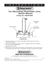
Please ensure that the leakage hole of the process connection is located at the deepest point of
the installed device.
1
G00169
Fig. 7
1 Leakage hole

Installation
14 - EN FSM4000 D184B141U02
Change from one to two colu mns
3.6 Installation Requirements
The device measures the flowrate in both directions. The factory
default is forward flow, as shown in
Fig. 8.
G00527
Fig. 8
The following items must be observed:
3.6.1 Electrode axis
Electrode axis (1) should be horizontal if at all possible or no more
that 45° from horizontal.
G00041
max. 45°
1
Fig. 9
3.6.2 In- and outlet pipe sections
Straight inlet section Straight outlet section
≥ 3 x DN ≥ 2 x DN
DN = Flowmeter sensor size
• Do not install fittings, manifolds, valves etc. directly in front of the
meter tube (1).
• Butterfly valves must be installed so that the valve plate does not
extend into the flowmeter sensor.
• Valves or other turn-off components should be installed in the
outlet pipe section (2).
• For compliance with the measuring accuracy, observe the inlet
and outlet pipe sections.
G00037
1
2
3xDN
2xDN
Fig. 10
3.6.3 Vertical connections
• Vertical installation for measuring abrasive fluids, preferably with
flow in upward direction.
G00206
Fig. 11
3.6.4 Horizontal connections
• Meter tube must always be completely full.
• Provide for a slight incline of the connection for degassing.
G00038
3°
Fig. 12
3.6.5 Free inlet or outlet
• Do not install the flowmeter at the highest point or in the draining-
off side of the pipeline, flowmeter runs empty, air bubbles can
form (1).
• Provide for a siphon fluid intake for free inlets or outlets so that
the pipeline is always full (2).
G00040
1
2
Fig. 13
3.6.6 Strongly contaminated fluids
• For strongly contaminated fluids, a bypass connection according
to the figure is recommended so that operation of the system can
continue to run without interruption the during the mechanical
cleaning.
G00042
Fig. 14

Installation
D184B141U02 FSM4000 EN - 15
3.6.7 Installation in the vicinity of pumps
• For flowmeter primaries that are installed near pumps or other
vibration-causing fixtures, the use of mechanical vibration control
components is mandatory.
G00207
Fig. 15
Change from one to two colu mns
3.7 Ground
3.7.1 General information on ground connections
Observe the following items when grounding the device:
• Use the supplied green-yellow cable as a ground wire.
• Connect the ground screw for the flowmeter sensor (on flange and transmitter housing) to
the station ground.
• The connection box must also be grounded.
• For plastic pipes or pipes with insulating lining, the ground is provided by the grounding plate
or grounding electrodes.
• When stray potentials are present, install a grounding plate at the front and back of the
flowmeter sensor.
• For measurement-related reasons, the potentials in the station ground and in the pipeline
should be identical.
• An additional ground via the terminals is not required.
Important
If the flowmeter sensor is installed in plastic or earthenware pipelines, or in pipelines with an
insulating lining, transient current may flow through the grounding electrode in special cases.
In the long term, this may destroy the flowmeter sensor, since the ground electrode will in turn
degrade electrochemically. In these special cases, the connection to the ground must be
performed using grounding plates.
3.7.2 Metal pipe with fixed flanges
G00530
1
2
Flange design Wafer design
Fig. 16

Installation
16 - EN FSM4000 D184B141U02
3.7.3 Metal pipe with loose flanges
G00531
12
3
Flange design Wafer design
Fig. 17
3.7.4 Non-metallic pipes or pipes with insulating liner
G00532
1
2
3
Flange design Wafer design
Fig. 18
3.7.5 Flowmeter sensor in stainless steel design model SE21
Ground the stainless steel model as shown in the figure. The measuring fluid is grounded via
the adapter (1) and an additional ground is not required.
G00533
1
Fig. 19
3.7.6 Ground for devices with hard rubber lining
For devices with meter sizes DN 125 and larger, the liner contains a conductive element. This
element grounds the measuring agent.
3.7.7 Ground for devices with protective plates
The protective plates are used to protect the edges of the liner in the measuring tube, e.g., for
abrasive fluids. In addition, they function as a grounding plate.
• For plastic or pipes with insulating lining, electrically connect the protective plate in the same
manner as a grounding plate.
3.7.8 Ground with conductive PTFE grounding plate
For devices with a meter size between DN 10 … 150, grounding plates made of conductive
PTFE are available. These are installed similar to conventional grounding plates.

Electrical connection
D184B141U02 FSM4000 EN - 17
4 Electrical connection
4.1 Preparing and routing the signal and magnet coil cable
Cut to length and terminate both cables as shown.
Important
Use wire end sleeves.
Signal cable D173D025U01 Magnet coil cable D173D147U01
Preparing the transmitter side
G00535
15
5
30 (1.18)
8
8
80 (3.15)
60 (2.36)
(0.20)
(0.59)
17 (0.67)
(0.31)
17 (0.67)
(0.31)
Preparing the flowmeter sensor side
G00549
5
4
3
2
1
G00552
M1
M3
1
2
3
Cable identifiers
Fig. 20: Dimensions in mm (inch)
1 Measurement potential, yellow
2 Reference, white
3 Signal cable, red
4 Signal cable, blue
5 SE clamp
1 Magnet coil, black
2 Magnet coil, black
3 SE clamp
Important
The shields may not touch (signal short circuit).

Electrical connection
18 - EN FSM4000 D184B141U02
Observe the following items when routing cables:
• The signal and magnet coil cable carries a voltage signal of only a few millivolts and
therefore must be routed the shortest distance possible. The maximum permissible signal
cable length is 50 m or 200 m, if the flowmeter sensor is equipped with a preamplifier.
• Avoid routing the cable in the vicinity of electrical equipment or switching elements that can
create stray fields, switching pulses and induction. If this is not possible, run the
signal/magnet coil cable through a metal pipe and connect this to the station ground.
• All leads must be shielded and connected to station ground.
• Do not run the signal cable and the magnet coil cable over junction boxes or terminal blocks.
• To shield against magnetic interspersion, the cable contains outer shielding that is attached
to the SE clamp.
• Make sure during installation that the cable
is provided with a water trap (1). For vertical
installation, align the cable glands pointing
downward.
G00058
1
Fig. 21
Important
For information about connecting or operating older models, refer to chapter 11 of the
operating instructions.
/