Page is loading ...

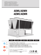
Air Cooled Water Chillers
Scroll Compressor
Refrigerant R290
35.4kW
31.7kW
SYSAQUA BLUE.L (Cooling Only)
SYSAQUA BLUE.H (Heat Pump)
Model 35B
SYSAQUA BLUE


SYSAQUA BLUE 1
R290 natural refrigerant,
Unit is optimized for partial load operation,
High SEER and Scop,
2compressorsttedintandemforalltherange,withan
immediate return on investment versus the inverter units,
"Night Mode" for energy savings and even more reduced
noise level in night operation,
Waterlawisstandardforenergysavings,
Possibility to combine up to 3 units,
Refrigerant circuit is completely closed in a separate
compartment in order to reduce noise level,
Great accessibility to internal components for service
operations,
Newdisplayonexternalpanelallowingthecompletecontrol
of the unit,
Wide operating limits,
High temperature operation up to 60 °C,
Operationinheatpumpmodedowntoexternaltemperature
of -20 °C,
Fanspeedcontrolforlowambientoperationincoolingmode
downto-15°C,
ModBusinterfaceavailable(reading/writing),
Phase sequence monitor supplied as standard,
User-friendlycontrollerthatallowstoreducetheneedof
anexternalwatertankinmostofcomfortairconditioning
installations,
Safety ventilation system patented
Controllogiconreturnorleavingwatertemperature,
Incoolingmode,3.5litresofbuffervolumeperkWare
recommended,
Newtechnology"smartdeice" standard for SYSAQUA BLUE.H
unitstoensureaconstanttemperatureoutofwaterevenat
verylowtemperatures
Doublewatersetpoint,
Waterlter(nottted)andwaterowswitch(factorytted)
are supplied as standard,
"Plugandplay"hydraulickitisstandard,
Automatic air vent,
Victaulic connection on internal components ensuring a
perfect sealing and facilitating service operations,
Pressuretappingpoint1/4"onwaterpipesforpressure
measurement,
Smallfootprint,allowingshippingandhandlingcoststobe
saved,unitsndeasilyaplacetobeinstalled.
Key Points
SYSAQUA BLUE
SYSAQUA BLUE.L/SYSAQUA BLUE.H
35B

SYSAQUA BLUE
2
Specications
General
The new SYSAQUA BLUE.L/SYSAQUA BLUE.H 35B have been
designedandoptimizedto operatewithR290refrigerantuid.
They are of single refrigerant circuit type.
They are available in cooling only (SYSAQUA BLUE.L) and heat
pump (SYSAQUA BLUE.H) versions.
Each unit delivers a nominal cooling capacity of 31.7 kW and a
nominal heating capacity of 35.4 kW.
All units are equipped with two scroll compressors tted in
tandem for adapting to partial system loads.
The general operation status of the machine is continuously under
the control of an IHM controller.
The SYSAQUA BLUE.L and SYSAQUA BLUE.H units can operate
without water tank,thankstotheIHMcontrollerthatimplements
an auto-adaptative control logic ensuring a total protection of the
compressorsatdifferentloadorwatervolumeconditions.
Theminimumwatervolumerequestedincoolingmodeis3.5L/kW
for application air conditioning and 10L/kW for application process.
In heating mode, 12.5L/kW are recommended in order to
guarantee homogeneous temperatures during the defrosting
cycles(comfortandenergysavings).
A fan speed controllercanbealsosuppliedasfactory-ttedoption
toauthorizetheunittooperateincoolingmodeatlowambient
temperature.
SYSAQUA BLUE.L and SYSAQUA BLUE.H units can be supplied in
several versions:
STD (Standard) version
HPF version : Increases the static pressure.
Cabinet and structure
The cabinet and structure of the unit are of heavy duty galvanized
steel. All galvanized steel components are individually painted by
a special painting process before the assembly of the unit.
This painting system performs a homogeneous protection to the
corrosion.Thepaintingisapolyesterpowderbasedtype,coloured
in RAL 7040.
The units SYSAQUA BLUE.L/SYSAQUA BLUE.H are suitable for
outdoor installation, directly on the building roof or at the ground
level.
Compressors
Eachunitisequippedwithtwoscrollcompressorsttedonarail
and assembled together to form tandem compressors.
The compressors are then mounted on rubber pads in order to
eliminate noise and vibration transmissions.
The compressor motors have a direct start-up. Each motor is cooled
bytherefrigerantgasandisequippedwithanoverloadprotection.
A phase sequence monitor is supplied as standard.
Evaporator
The evaporator is consisting of a stainless steel plate heat
exchangerinsulatedwithclosedcellsyntheticfoam.Itisprotected
by an antifreeze electric heater to ensure a good protection
againstfreezingatlowambienttemperature(-10°Cmin.)when
theunitisswitchedoff.
Maximum working pressure is 10 bar at water side and
27.2bar(g) at refrigerant side.
Condenser
Thecondenserisannedcoilconstructedwithseamlesscopper
tubes mechanically expanded into aluminium ns. The ns of
SYSAQUA BLUE.Hcoilsaremadeofaluminiumwithhydrophylic
bluecoatingtofacilitatewaterdropletsdrain.
The condenser is largely dimensioned in order to optimize
performance and defrosting cycles.
The condenser can be equipped, as optional, a protective grille to
preventshocks.
Condenser fans and motors
The fan motor has IP54 grade and is equipped with a thermal
overload protection.
A pressostatic type fan speed controller can be delivered as
factory-ttedoption.Itallowstheunittooperateincoolingmode
atlowambienttemperaturesdownto-10°Cminimum,because
it regulates the fan speed in order to maintain the constant
condensing temperature.
Allfansarettedwithaprotectivegrilleontop.
Refrigerant circuit
All units have one refrigerant circuit consisting of : scroll tandem
compressors,plateheatexchanger,thermostaticexpansionvalve,
4-wayreversecyclevalveandliquidreservoir(heatpumpversion
only),condensercoil,aswellassafetyandcontroldevicessuch
ashighpressureswitch, high/lowpressuretransducersandPED
safety valve.
Inspection on refrigerant via a sight glass can be done during
serviceoperations,byremovinganaccesspanel,withoutdisturbing
the unit operating conditions.
AsetofLPandHPgaugescanbefactoryttedasoptional.
Allrefrigerantcomponentsareshowninthefunctionaldiagrams
illustratedinthenextpages,section"Refrigerantowdiagrams".
Hydraulic circuit
Thankstothedesignexibilityonthehydrauliccircuit,alltheunits
canbeconguredinseveralways:
BASIC unit:Unitwithoutpump,thehydrauliccircuit
containsthefollowingcomponents:suppliedloose
waterlter,mountedwaterowswitch,watersafety
valve,automaticairvent,optionaleld-installed
in/out3/8"watervalves.
Allwaterpipingiscoveredwiththermalinsulation.
1P-SP : One pump unit having the same equipment
asBASICunit+apumpwith150kPaexternalstatic
pressure.Anairventisprovidedforthisconguration.
"Variable Primary Flow" is used to modulate the
powerofthehydraulicpump
The differentcomponentsofhydraulickitareinterconnected by
Victaulic couplings in order to facilitate maintenance operations.
The hydraulic connections are of male gas threaded type; for the
connection diameters, please refer to the physical data tables on
thenextpages.

SYSAQUA BLUE 3
Specications
Control panel
Theunitsarettedwithanexternalcontrolpanelthatdisplaysthe
operating parameters and alarms.
The control panel is accessible from exterior without removing
anyparts,norshuttingdowntheunit,becauseitisplacedonan
externalpanel.
The SYSAQUA BLUE.L/SYSAQUA BLUE.H chillers are equipped
with a microprocessor based control with a new IHM logic that
implements an intelligent control with anticipation of needs, either
onenteringwatertemperature,oronleavingwatertemperature.
The main features of this control system are :
OUser-friendly : with only 6 buttons and a tree logic, it is
possible to control the unit easily,
OReliable : all indications on the display are visible in every
weatherconditions,
OInternal test procedure,
OAlarmvisualizationwithaloggingofthelast10alarms,
ORemoteON/OFFswitching,
OCompressorandpumpworkinghourcounter,
OPressure transducers to control discharge and suction
temperatures,
OMaximumdischargetemperaturecontrol,
OPart load operating mode,
ORemoteCooling/Heatingmodeswitching,
OCompatibilitywithBMS(RS485ModBusRTUorBacNetMSTP
protocol),
OCompressoroperatinglimitsstoredinaashmemory.
Control and safety devices
Eachunitiscompletewiththefollowingsafetyandcontroldevices
:
Safety :
Fan motor overload protection.
Compressor motor overload protection.
Waterowswitch.
Waterlter(suppliedloose).
Highpressureswitch.
Highandlowpressuretransducers.
Evaporator antifreeze electric heater.
Crankcaseheater.
Safety valve on 27.2 bar refrigerated side.
Safetyvalveon3barwaterside.
Module de détection de gaz.
Control :
Enteringwatertemperaturesensor.
Leavingwatertemperaturesensor.
Coil temperature sensor.
Discharge temperature sensor.
Air temperature sensor.
Suction and discharge pressure transducers.
Dry contact available to the client:
ON / OFF, SUMMER / WINTER, Day / Night.
Conformity with standards
All SYSAQUA BLUE.L/SYSAQUA BLUE.Hunitsareincompliancewith
thefollowingstandards:
Machine Directive : 2006/42/EC
LowVoltageDirective:2014/35/UE
Electromagnetic Compatibility Directive : 2014/30/UE
Pressure Equipment Directive : 2014/68/UE
RoHsdirective:2011/65/EU
Factory-installed options
Condenser protective grille.
Coilwithepoxytreatment.
Lackofwaterpressureswitch.
1-pumphydraulickit
VariablePrimaryFlow
double speed
capacity
constant outlet pressure
Fanspeedcontrolkit(foroperationwithlowambient
temperaturedownto-10°C).
NordicPackincludingaprotectionoftheexternalcoils
andaheatingwireincondensatetray.
Field-installed accessories
Anti-vibration rubber pads or spring damper.
In/Outvalvekit.
User interface

SYSAQUA BLUE
4
Models designation
REP. Description
1
Size
SYSAQUA35B: size35
2
Version L : Cooling only H : Heat pump
3Hydraulic
circuit Empty : Without pump 1P-SP: PackSinglepump
4
Regulation STD : Standard FSC : All seasons
5
Brand SYS : Systemair
6Fan type AC : Standard fan AC motor HPF : High pressure fan
7
Option
CG : Outdoor coil protection grid
EPO : Finnedcoiltreatment-epoxy
WPS : Lowwaterpressuresensor
AVS : Spring damper
AVM : rubber pads
VI : Water isolation valves
T : Buffertank
SS : Soft Starter
NORD: Packnordic
V2 : Variable pump double speed
VC : Variable pump capacity
VP : Variable pump constant outlet pressure
4G : 4G modem
SYSAQUA35B . H . 1P-SP . STD . SYS . AC . + . CG . T
1
2
3
4
5
6
7
7

8
M2
M1
RV1
4
5
6
7
3
OF1
SV HP
IV
SV LP
OCT
OAT
FPE
CST
FPCHPCDT
WATER
8
M2
M1
45
6
3
OF1
SV HP
IV
SV LP
FPE
CST
OCT
FPCHPCDT
OAT
WATER
SYSAQUA BLUE 5
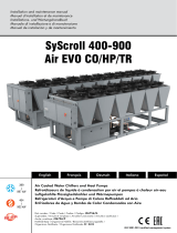
Refrigerant Flow Diagram
safety/control devices
FCP High pressure transducer
HP High pressure switch
CDT Discharge temperature sensor
FPE Low pressure transducer
PS Expansion valve pressure tap
OAT Outdoor air temperature sensor
OCT Condenser outlet temperature sensor
SV HP Service valve HP
SV LP Service valve BP
IV Isolating valve
components
M1/M2 Tandem scroll compressors
RV1 Cycle reversal valve
OF1 Outdoor fan motor
3Air cooled condenser
4Filter drier
5Sight glass
6Electronic expansion valve
7Liquid reservoir
8Plate heat exchanger
Pressure tapping point 1/4"
Cooling only version - SYSAQUA BLUE.L
Heat pump version - SYSAQUA BLUE.H

LWC
VD
FS
CL
LWT
EWT
RAG RAG
PHE
EWC
FT CL
PA
MN
MN
VV
VR
CF
CF
VA
VA
LWC
VD
FS
CL
LWT
EWT
RAG RAG
PHE
EWC
WP
WPT
PA
WT
FT
VE
WPS
CL
SS
CL
PA
SYSAQUA BLUE
6
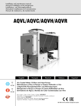
Hydraulic Circuit Diagram
Recommended installation
VA Globe valve (option)
VV Drain valve
CF Connexion flexible
VR Water charging valve
MN Manometer
Hydraulic Circuit
FT Filter (supplied loose)
EWC/LWC Inlet/Outlet gas male connection
1"1/2
VE Pressure expansion tank
WPS Lack of water pressure switch (optional)
SS Safety valve
WP Pump
PA Automatic air vent
CL Pressure tap 1/4''
EWT Inlet water temperature sensor
LWT Outlet water temperature sensor
PHE Plate heat exchanger
RAG Antifreeze heater
FS Flow switch
VD Drain valve
WT Buffer tank
WPT Pressure transducer (optional)
Without pump version
Recommended installation - Single pump version
UnitInstallation

G
F
E
D
C
B
A
A+
A++
Less efcient
More efcient
SYSAQUA BLUE 7
Operating Limits
* Below5°C,glycolisrequired.
SYSAQUA BLUE.L/SYSAQUA BLUE.H in cooling mode
SYSAQUA BLUE.H in heating mode
** considered at nominal unit capacity
** considered at nominal unit capacity
Energy performance
Energy class
SeasonalspaceheatingenergyefciencyclassaccordingtotheDelegatedRegulation
No. 811/2013 of the European Commission.
*AccordingtoEN14511-2013
SYSAQUA BLUE.H 35B
SCOP *
3.54
Class
G
F
E
D
C
B
A
A+
A++
SYSAQUA BLUE.L/SYSAQUA BLUE.H models 35B
Min. Max.
Eau
Water outlet temperature * °C -15 18
Water ∆T ** K3 12
Flow rate ** m3/h 3.4 9
Air temperature °C See diagrams on next page
SYSAQUA BLUE.H models 35B
Min. Max.
Water
Water outlet temperature °C 20 60
Water ∆T ** K3 12
Flow rate ** m3/h 3.4 9
Air temperature °C See diagrams on next page

-20
-15
-10
-5
0
5
10
15
20
25
30
35
40
45
50
55
-20 -15 -10 -5 0 5 10 15
20
Leaving water temperature (°C)
BRINES or
WATER + GLYCOL
+ Fan speed controller
WATER + Fan
speed controller
BRINES or
WATER + GLYCOL WATER
OAT - Outdoor air temperature (°C)
-25
-20
-15
-10
-5
0
5
10
15
20
25
15 20 25 30 35 40 45 50 55 60
65
Leaving water temperature (°C)
OAT - Outdoor air temperature (°C)
SYSAQUA BLUE
8
SYSAQUA BLUE.L/SYSAQUA BLUE.H in cooling mode
SYSAQUA BLUE.H in heating mode
Operating Limits

SYSAQUA BLUE 9
Correction Factors
Fouling factors - Evaporator
Altitude factors
Correction factors - Ethylene glycol
Correction factors - Propylene glycol
Fouling factor (m2.°C/kW) Capacity Power input
0.044 1.000 1.000
0.088 0.987 0.995
0.176 0.964 0.985
0.352 0.915 0.962
Altitude (m) Capacity Power input
0 1.000 1.000
600 0.987 1.010
1200 0.973 1.020
1800 0.958 1.030
2400 0.943 1.040
% glycol Freezing point
(°C) Capacity Power input Water ow Pressure drop
0 0 1.00 1.00 1.00 1.00
10 -3 0.991 0.994 1.005 1.112
20 -7 0.977 0.991 1.030 1.175
30 -13 0.945 0.975 1.067 1.290
45 -27 0.894 0.962 1.162 1.520
% glycol Freezing point
(°C) Capacity Power input Water ow Pressure drop
0 0 1.00 1.00 1.00 1.00
10 -4 0.995 0.998 1.015 1.070
20 -10 0.985 0.995 1.050 1.160
30 -17 0.970 0.985 1.085 1.235
45 -30 0.949 0.977 1.169 1.368
Fouling factors - Condenser
Fouling factor (m2.°C/kW) Capacity Power input
0.044 1.000 1.000
0.088 0.987 1.023
0.176 0.955 1.068
0.352 0.910 1.135
Warning !
Ethyleneglycolistoxictotheenvironment.Moreover,itisnotsuitableforheatingwithdomestichotwater
productionbysimpleexchange.

SYSAQUA BLUE
10
SYSAQUA BLUE - Cooling only version 35B
Cooling capacity kW 31.7
Power input kW 10.2
Total EER 100% (1) 3.10
Energy class EER A
SEER (2) 4.33
hsc (2) 170.0
Energy class SEER C
Power supply 400V/3~+N/50Hz
Startup type Direct
Maximum operating current A 34.0
Startup current (without Soft Starter) A 120.0
Startup current (with Soft Starter) A 54.6
REFRIGERANT
Type R290
Number of refrigerant circuit 1
Charge kg 2.8
COMPRESSORS
Number 2
Type Scroll
Part load steps % 0/50/100
Crankcase heater W 2 X 53
EVAPORATOR
Number 1
Type Plate
Water flow m³/h 5.40
Water pressure drop kPa 18
Water volume l 3.32
Antifreeze heater W 30
COIL
Number 1
Frontal surface m22.79
Number of rows 2
FAN
Number 1
STD
Air flow m³/h 15 840
Rotational speed tr/mn 675
Power input each fan W 695
HPF
Air flow m³/h 15 840
Rotational speed tr/mn 874
Power input each fan W 1 922
Static pressure Pa 170
WATER CONNECTIONS
Type Male gas threaded
Inlet diameter pouces 1"1/2
Outlet diameter pouces 1"1/2
BUFFER TANK (OPTION)
Volume L 100
DIMENSIONS
Length mm 1 000
Width mm 1 000
Height STD mm 1 983
HPF mm 2 025
WEIGHT
Operating weight kg 312
ACOUSTICAL DATA
Sound power level dB(A) 83
Sound pressure level (*) dB(A) 55
Physical Data - SYSAQUA BLUE.L STD
(*) Sound pressure levels calculated at 10 meters. Sound pressure
levelsrefertoISOstandard3744withparallepipedshape.
(1) According to EN14511-
2013
(2)AccordingtoEurovent

SYSAQUA BLUE 11
SYSAQUA BLUE - Heat pump version 35B
Cooling capacity kW 31.7
Power input kW 10.2
Total EER 100% (1) 3.10
Energy class EER (2) A
SEER (2) 4.33
hsc (2) 170.0
Energy class SEER C
Heating capacity kW 35.4
Power input kW 10.3
Total COP 100% (1) 3.5
SCOP (2) 3.5
hsh (2) 139.0
Energy class SCOP (2) A+
Power supply 400V/3ph+N/50Hz
Startup type Direct
Maximum operating current A 34.0
Startup current (without Soft Starter) A 120.0
Startup current (with Soft Starter) A 54.6
REFRIGERANT
Type R290
Number of refrigerant circuit 1
Charge kg 2.8
COMPRESSORSS
Number 2
Type Scroll
Part load steps % 0/50/100
Crankcase heater W 2 X 53
EVAPORATOR
Number 1
Type Plate
Cooling mode Water flow m³/h 5.40
Water pressure drop kPa 18.20
Heating mode Water flow m³/h 6.10
Water pressure drop kPa 22.50
Water volume l 3.32
Antifreeze heater W 30
COIL
Number 1
Frontal surface m22.79
Number of rows 2
FAN
Number 1
STD
Air flow m³/h 15 840
Rotational speed tr/mn 675
Power input each fan W 695
HPF
Air flow m³/h 15 840
Rotational speed tr/mn 874
Power input each fan W 1 922
Static pressure Pa 170
WATER CONNECTIONS
Type Male gas threaded
Inlet diameter pouces 1"1/2
Outlet diameter pouces 1"1/2
BUFFER TANK (OPTION)
Volume L 100
DIMENSIONS
Length mm 1 000
Width mm 1 000
Height STD mm 1 983
HPF mm 2 025
WEIGHT
Operating weight kg 312
ACOUSTICAL DATA
Sound power level dB(A) 83
Sound pressure level (*) dB(A) 55
Physical Data - SYSAQUA BLUE.H STD
(*) Sound pressure levels calculated at 10 meters. Sound pressure
levelsrefertoISOstandard3744withparallepipedshape.
(1) According to EN14511-
2013
(2)AccordingtoEurovent

SYSAQUA BLUE
12
Electrical Data
Unit without pump with condenser fans
standard
Unit without pump with condenser fans
HPF
Weight
Simple pump 1P (400V / 3~N / 50Hz)
Unit with standard pump and condenser
fans standard
Unit with standard pump and condenser
fans HPF
Sizes 35B
Power supply 400V / 3~N / 50Hz
Maximum current A 37.0
Total startup current (without
Soft Starter) A 123.0
Total startup current (with Soft
Starter) A 57.6
Sizes 35B
Power supply 400V / 3~N / 50Hz
Maximum current A 39.0
Total startup current (without
Soft Starter) A 125.0
Total startup current (with Soft
Starter) A 59.6
Sizes Nominal power
(kW)
Max. current
(A)
35B 0.9 2.4
Sizes 35B
Power supply 400V / 3~N / 50Hz
Maximum current A 34.0
Total startup current (without
Soft Starter) A 120.0
Total startup current (with Soft
Starter) A 54.6
Sizes 35B
without pump kg 307
Simple pump kg +20
buffer tank (dry weight) Kg +65
Sizes 35B
Power supply 400V / 3~N / 50Hz
Maximum current A 36.0
Total startup current (without
Soft Starter) A 122.0
Total startup current (with Soft
Starter) A 56.6

2 3 4 5 6 7 8 9
20
1 10
2
3
4
5
6
7
8
9
20
30
40
50
60
70
80
90
200
1
10
100
35
Water flow
(m
3
/h)
Pressure loss
(kPa)
SYSAQUA BLUE 13
Acoustical Data
Sound power level Lw-dB - condenser fans standard
(*) Soundpressurelevelscalculatedat10meters.SoundpressurelevelsrefertoISOstandard3744with
parallepiped shape.
Sound power level Lw-dB - condenser fans HPF
SYSAQUA BLUE.L/
SYSAQUA BLUE.H
models
Frequency in octave band (Hz) Lw global
dB (A)
Sound
pressure level
dB(A) *
125 250 500 1000 2000 4000
35B 60 60 67 78 74 80 83 55
SYSAQUA BLUE.L/
SYSAQUA BLUE.H
models
Frequency in octave band (Hz) Lw global
dB (A)
Sound
pressure level
dB(A) *
125 250 500 1000 2000 4000
35B 59 74 73 79 76 80 84 56
Water Pressure Drop of Indoor Heat
Exchanger

30 Hz
35 Hz
40 Hz
45 Hz
50 Hz
0246810
12
0
50
100
150
200
250
300
Water flow
(m
3
/h)
Available pressure
(kPa)
30 Hz
35 Hz
40 Hz
45 Hz
50 Hz
0246810
12
0.00
0.20
0.40
0.60
0.80
1.0.0
1.20
1.40
Water flow
(m
3
/h)
Power Input (k
W)
SYSAQUA BLUE
14
Water Pump Curves

208
102
173
178
572
Ø1"1/2
1 00053
1 983
1 000
1 175
INTLET
WATER
OUTLET
Top view Bottom view
Front view Rear viewSide view
208
102
173
178
572
Ø1"1/2
1 00053
2 025
1 000
1 175
INTLET
WATER
OUTLET
Top view Bottom view
Front view Rear viewSide view
SYSAQUA BLUE 15
Dimensions (mm)
SYSAQUA BLUE.L/SYSAQUA BLUE.H - fan standard
SYSAQUA BLUE.L/SYSAQUA BLUE.H - fan HPF

1 507
1 000 53
1 983
1 175
92
173
246
383
691
Ø1"1/2
INTLET
WATER
OUTLET
Top view Bottom view
Front view Side viewSide view
1 507
1 000 53
2 025
1 175
92
173
246
383
691
Ø1"1/2
INTLET
WATER
OUTLET
Top view Bottom view
Front view Side viewSide view
SYSAQUA BLUE
16
Dimensions (mm)
SYSAQUA BLUE.L/SYSAQUA BLUE.H with buffer tank - fan standard
SYSAQUA BLUE.L/SYSAQUA BLUE.H with buffer tank - fan HPF

5 00
1 000
5 00
1 000
1 507
Ø900
Ø955
Ø12
328
47
500
1 000
500
1 000
SYSAQUA BLUE 17
Duct outlet dimensions (mm)

2 000
2 000
3 000
2 000
2 000
2 000
2 000
3 000
2 000
2 000
SYSAQUA BLUE
18
Space Requirements (mm)
SYSAQUA BLUE.L/SYSAQUA BLUE.H
/