PEAK IPEH-002022 User manual
- Category
- Interface cards/adapters
- Type
- User manual
This manual is also suitable for
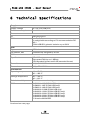
PEAK IPEH-002022 is a PCAN-USB (ISO) adapter that seamlessly connects a High-speed CAN (CAN specifications 2.0A and 2.0B) to a PC via USB. With galvanic isolation at CAN connection up to 500 V, it ensures reliable data transmission and protection against electrical disturbances. The adapter supports Windows (98 SE, ME, 2000 SP4, XP) and Linux operating systems, making it versatile for various applications.
PEAK IPEH-002022 is a PCAN-USB (ISO) adapter that seamlessly connects a High-speed CAN (CAN specifications 2.0A and 2.0B) to a PC via USB. With galvanic isolation at CAN connection up to 500 V, it ensures reliable data transmission and protection against electrical disturbances. The adapter supports Windows (98 SE, ME, 2000 SP4, XP) and Linux operating systems, making it versatile for various applications.


-
 1
1
-
 2
2
-
 3
3
-
 4
4
-
 5
5
-
 6
6
-
 7
7
-
 8
8
-
 9
9
-
 10
10
-
 11
11
-
 12
12
-
 13
13
-
 14
14
-
 15
15
-
 16
16
-
 17
17
-
 18
18
-
 19
19
-
 20
20


PEAK IPEH-002022 User manual
- Category
- Interface cards/adapters
- Type
- User manual
- This manual is also suitable for
PEAK IPEH-002022 is a PCAN-USB (ISO) adapter that seamlessly connects a High-speed CAN (CAN specifications 2.0A and 2.0B) to a PC via USB. With galvanic isolation at CAN connection up to 500 V, it ensures reliable data transmission and protection against electrical disturbances. The adapter supports Windows (98 SE, ME, 2000 SP4, XP) and Linux operating systems, making it versatile for various applications.
Ask a question and I''ll find the answer in the document
Finding information in a document is now easier with AI
Related papers
-
PEAK PCAN-USB Hub User manual
-
PEAK GC-CAN-USB-ISO User manual
-
-
PEAK PCAN-DONGLE IPEH-002015 User manual
-
-
-
-
-
-
Other documents
-
 PEAK-System PCAN-Dongle Operating instructions
-
 PEAK-System Technik RS-232 User manual
-
 PEAK-System PCAN-USB Operating instructions
-
 PEAK-System PCAN-USB X6 Operating instructions
-
 PEAK-System PCAN-USB Pro Operating instructions
-
-
 PEAK-System PCAN-USB Pro FD Operating instructions
-
 PEAK-System PCAN-USB Pro FD Operating instructions
-
PEAK-System PCAN-Router Pro FD Operating instructions
-
 PEAK-System PCAN-Router FD Operating instructions


