ESAB R-50 Series Controlled Flow Cylinder Regulators Troubleshooting instruction
- Category
- Welding System
- Type
- Troubleshooting instruction

INSTRUCTIONS for
F14-237
April, 2007
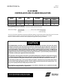
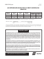
R-50 SERIES
CONTROLLED FLOW CYLINDER REGULATORS
Be sure this information reaches the operator.
You can get extra copies through your supplier.
CGA-032 (FORMERLY "B"I.G.)—5/8—18RH female.
Each regulator is equipped with 1.50" (38 mm) dia., 0 - 4000 psi (0 - 276 bars) cylinder pressure gauge.
Dimensions Weight: Overall length ................................4.25" to 4.75" (108 mm to 120 mm)
Body Diameter ....................................................................... 1.25" (32 mm)
Weight ...................................................................................1.00 lb. (0.45 kg)
Accessory: CO
2
Heater, P/N 950578 - Recommended if CO
2
regulator is expected to operate at high duty cycles. The heater
connects between regulator and cylinder permitting the CO
2
to ow without "freezing up" the regulator.
Requires standard electrical extension cord of appropriate length with 3-prong connections.
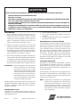
The INSTRUCTIONS contained on this sheet are intended specically for operators who know the general
principles of operation and safe practices to be followed in operating this type of equipment. If you are not
sure that you understand these principles fully, we urge you to read our booklet "Precautions and Safe Prac-
tices for Arc Welding, Cutting and Gouging" Form 52-529, in addition to these instructions. Do NOT permit
untrained persons to install, operate, or maintain this equipment. Do NOT attempt to install or operate this
equipment until you have read and fully understand these instructions. If you do not fully understand these
instructions, contact your supplier for further information.
The regulators covered by these Instructions are listed by Underwriter's Laboratories only when using parts
manufactured by The ESAB Group to the specications on le with Underwriter's Laboratories, Inc., and the
gas service for which it is designed and listed. The use of other parts voids the manufacturer's warranty.
Do not clamp regulator cap in a vise or grip it with a pair of pliers. Distortion of cap can jam the internal parts
and cause excessively high delivery pressure as well as weaken the threaded joint to the regulator body. This
may cause cap to y o and possibly injure personnel in area.
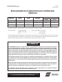
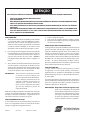
The regulators are not adjustable. They are factory set to deliver a xed ow rate as specied in the table
above. Do not attempt to make any adjustments.
CAUTION
Regulator
Model
Part
Number
Gas
Service
Preset Nom.
Flow Rate
Connections (CGA)
Inlet Outlet•
R-50-TIG-580 18361 Argon 25 cfh (0.71 m
3
/hr.) 580 032
R-50-MIG-580 17773 Argon Mix 35 cfh (0.99 m
3
/hr.) 580 032
R-50-MIG-320 17774 CO
2
35 cfh (0.99 m
3
/hr.) 320 032

1. Close the cylinder valve.
2. Release gas from the regulator by opening valve
downstream.
3. When pressure gauge reads zero, the regulator may
be removed from the cylinder.
INLET FILTER MAINTENANCE
Each regulator is equipped with a porous metal inlet lter,
P/N 71Z33, pressed into the regulator inlet nipple. No
regulator should be connected to a cylinder or station
valve unless it contains this lter. You can replace the
lter if you have reason to do so. To remove a lter, insert
a No. 1 "EZY-OUT" or a No. 6 wood screw (about 2.00" - 51
mm long) into the lter and pull it out. Carefully press
the new lter into the nipple with a 0.25" (6.4 mm) round
metal rod.
REPAIR SERVICE
If gas is escaping through the safety release device, or if
any leakage was noted, the regulator should be returned
to your distributor or to ESAB Remanufacturing Center,
411 S. Ebenezer Road, Florence, SC 29501.
If you have your own properly equipped and staed repair
facility, repair parts information for this regulator (Form
F14-239) is available on request to your distributor.
NOTE: Safety release device equipped on these regula-
tors is designed for regulator protection; not for
hose or equipment downstream. If gas escapes
through the safety release device, immediately
close cylinder valve and then remove regulator
from service for repair.
F14-237 04 / 2007 Printed in U.S.A.
TO CONNECT:
1. Open the cylinder valve slightly for an instant, and
then close it. This is known as cracking the valve. This
blows away and dirt or dust which may have accumu-
lated in the valve outlet. Be sure to keep your face
away from the valve outlet to protect your eyes.
2. Attach the torch hose to the regulator outlet ("B"- size
inert gas female connection) and tighten the con-
nection snugly with a wrench. (A shuto valve, such
as the OXWELD V-30 Argon-Water Shuto Valve, P/N
16X21, may be connected between the regulator and
torch if desired.
3. Open the cylinder valve slowly a fraction of a turn.
When the cylinder pressure gauge pointer stops mov-
ing, open the valve fully. Never stand directly in front
of or behind the regulator when opening the cylinder
valve. Always stand to one side.
IMPORTANT: Before starting operation, test all con-
nections with a Leak Test Solution
such as P/N 998771. Correct any leaks
before starting work. Testing should be
performed after torch or other gas-using
device has been properly connected,
with valve(s) downstream of regulator
closed.
Also, check all joints on the regulator, including vent holes
in the cap, for leakage. If leakage is noted, the regulator
should be removed from service and sent out for repair.
TO STOP FLOW
If work is to be stopped for a half-hour or more, or the
regulator is to be removed from the cylinder, shut down
the regulator as follows:
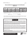
INERT GAS OR CARBON DIOXIDE CAN CAUSE SUFFOCATION IN CONFINED SPACES.
ALWAYS WORK IN WELL VENTILATED AREA.
PREVENT LEAKS.
DO NOT CHANGE CGA INLET CONNECTION FROM NUMBER STAMPED ON REGULATOR BODY.
FOLLOW OPERATING INSTRUCTIONS ON THIS SHEET.
THIS REGULATOR MUST BE INSTALLED, OPERATED AND MAINTAINED ONLY BY TRAINED SERVICEMEN.
FOR COMPLETE SAFETY INFORMATION ON WELDING AND CUTTING EQUIPMENT, READ FORM 2035 (OXY-
FUEL GAS) AND 52-529 (ARC WELDING). FOR SAFETY INFORMATION ON GASES, SEE YOUR SUPPLIER.
•
•
•
•
•
•
WARNING
Page is loading ...
Page is loading ...
Page is loading ...
Page is loading ...
Page is loading ...
Page is loading ...
-
 1
1
-
 2
2
-
 3
3
-
 4
4
-
 5
5
-
 6
6
-
 7
7
-
 8
8


ESAB R-50 Series Controlled Flow Cylinder Regulators Troubleshooting instruction
- Category
- Welding System
- Type
- Troubleshooting instruction
Ask a question and I''ll find the answer in the document
Finding information in a document is now easier with AI
in other languages
Related papers
-
ESAB R-50 Series Controlled Flow Cylinder Regulators Troubleshooting instruction
-
-
-
-
-
-
-
-
-
Other documents
-
HERMA Frame IT Installation guide
-
Campbell Hausfeld Thermostat WT6000 User manual
-
ADVANCE EZY 80 Owner's manual
-
Lincoln WELD-PAK 3200HD User manual
-
Lincoln Electric MIG-PAK 10 Operating instructions
-
-
-
Century Wire Feed 100 User manual
-
 Pegasus Astro PEG-EZYFOCUS User manual
-
