Page is loading ...

Camera Dome
Installation and Service
Manual

SpeedDome*
Camera Dome
Installation and Service Manual
8000-1715-01, Rev. A
WLG 1 O/97

FCC COMPLIANCE
This equipment has been tested and found to comply with Part 15
of the FCC Rules. Operation is subject to the following two
conditions: 1) this device may not cause harmful interference, and
2) this device must accept any interference received, including
interference that may cause undesired operation.
EQUIPMENT MODIFICATION CAUTION
Equipment changes or modifications not expressly approved by
Sensormatic Electronics Corporation, the party responsible for
FCC compliance, could void the user’s authority to operate the
equipment.
WARRANTY DISCLAIMER
Sensormatic Electronics Corporation makes no representation or
warranty with respect to the contents hereof and specifically
disclaims any implied warranties of merchantability or fitness for
any particular purpose. Further, Sensormatic Electronics
Corporation reserves the right to revise this publication and make
changes from time to time in the content hereof without obligation
of Sensormatic Electronics Corporation to notify any person of
such revision or changes.
LIMITED RIGHTS NOTICE
For units of the Department of Defense, all documentation and
manuals were developed at private expense and no part of it was
developed using Government Funds. The restrictions governing
the use and disclosure of technical data marked with this legend
are set forth in the definition of “limited rights” in paragraph (a)
(15) of the clause of DFARS 252.227.7013. Unpublished - rights
reserved under the Copyright Laws of the United States.
No part of this manual may be reproduced in any form without
written permission from Sensormatic Electronics Corporation.
SensorVision and SpeedDome are trademarks of Sensormatic
Electronics Corporation. Product names mentioned herein may be
trademarks or registered trademarks of other companies.
0 Copyright Sensormatic Electronics Corporation 1997.

1.0
1.1
1.2
1.3
1.4
2.0
2.1
2.2
2.3
2.4
2.5
Using this manual ........................................................................................................
v
INTRODUCTION
..................................................................................................
l-l
WHAT IS SpeedDome?. ............................................................................................
1-l
SpeedDome FEATURES.. .........................................................................................
l-2
IINSTALLATION METHODS .....................................................................................
l-6
SPECIFICATIONS .....................................................................................................
l-8
INSTALLATION.. ..................................................................................................
2-l
PRE-INSTALLATION GUIDELINES.. ........................................................................
.2-l
SAFETY PRECAUTIONS ...........................................................................................
2-2
INDOOR MOUNTING METHODS..
........................................................................... 2-2
OUTDOOR
MOUNTING METHODS.. ....................................................................... 2-2
ADDITIONAL INFORMATION.. ................................................................................
.2-2
Appendix A
Appendix B
Appendixes
American Dynamics to SpeedDome
Interconnection .............................................
A-l
SensorNet and UniCard..
.........................................................................................
B-l
iii

Using this manual
Use this manual when installing Sensormatic SpeedDomes for
the first time. Use it later as a guide for maintenance and
troubleshooting.
Sections included in this manual
This manual contains four sections arranged as follows:
1.0 INTRODUCTION
provides a product overview and
specifications.
20
INSTALLATION
provides background and procedures
required to install and adapt the unit to its environment.
Wuick Reference Guide”
The quick reference guide
portion of the Installation and Service chapters provides
procedures, wiring diagrams, and cable terminations in a
reference format. Copy appropriate pages for use in the
field.
Appendixes
contain information on attaching SpeedDome
camera domes to American Dynamics systems and
SensorNeWnicard domes.
Questions?
For technical support or questions that this manual does not
address:
Customer Engineers call l-800-543-9740.
Dealers call l-800-442-2225
IV

Introduction
1.1 WHAT IS
SpeedDome’“?
The SensorVision SpeedDome (Figure l-l) is a programmable
dome designed for retail stores, casinos, manufacturing facili-
ties, hotels, hospitals, and a wide variety of other facilities,
especially where appearance is an important consideration.
The SpeedDome is part of a SensorVision CCTV (Closed Circuit
Television) system, a network of remote camera devices. The
dome pans, tilts, zooms, and focuses on the subject, whether it
is in low light, moving, or at a distance.
Manual operation enables these functions to be controlled by a
host control system from a centrally located console. Automatic
operation enables the dome to store, and recall at a later time,
camera scenes or field of views (Targets/Presets) and a series
of pan/tilt/zoom movements (Patterns). SpeedDome can also
activate or respond to external security devices.
Compact, Visible Dome.
SpeedDome is visually
appealing and unobtrusive. The dome chassis consists of a
carriage assembly hidden inside a protective housing with a
ceiling-mounted, gloss black “eyeball” suspended from it. The
carriage assembly contains the dome’s power supply, a pan
motor assembly, and electronic circuitry used to operate the
dome. The eyeball, only 19cm (7.5”) in diameter, houses a
camera, camera electronics, lens, lens motors, and tilt
assembly.
SENSORVISION SpeedDome l-l

Monochrome and Color Cameras.
The Speed-
Dome uses monochrome or color cameras. Monochrome
cameras come in l/2’ CCD, EIA, 60Hz and l/2” CCD, CCIR,
50Hz versions. Color cameras come in l/2” CCD, NTSC, 60Hz
and l/2” CCD, PAL, 50Hz versions.
The color camera is fully digital, which has several advantages
over analog versions. It has no field adjustments, and better
light sensitivity (2.2 lux) and picture resolution (430 TV lines) due
to Digital Signal Processing (DSP).
Camera Lens.
The indoor version uses a motorized 8-
80mm, fl.2 lens; the outdoor version uses an &80mm, fl.2 lens
or an fl.8, 12-120mm lens. The lens and associated electronics
provide a totally unique Iris Preferencel that automatically
adapts the picture to even the most difficult lighting conditions
(see “Iris Preference’“” under features).
Camera/Lens Concealment.
For indoor versions, a
clear, acrylic “contact lens” mounts flush with the contour of the
eyeball to prevent detection of the camera’s viewing position.
For indoor versions, outer acrylic bubbles, available in clear,
tinted, gold, or mirrored finishes further conceal the camera’s
viewing position or customize its appearance to blend with
special decors.
1.2 SpeedDome FEATURES
Performance Features
In alphabetical order:
l
Alarm inputs and outputs. The SpeedDome accepts
dry-contact switch closures from four different sensing
devices. This or any other system camera can then be
programmed to scan or position itself to observe alarms and
events. Onboard outputs enable the SpeedDome to control
other activities such as turning on lights or initiating sound
messages.
l
Apple Peel Default Pattern. When no programmed
patterns are entered into its software, the SpeedDome auto-
matically defaults to an “apple peel” pattern. It initially aims
along the ceiling and then performs 360” pans: 3 for the
indoor mount and 3 for the outdoor mount, dropping 30”
after each pan.
1-2
SENSORVISION
SpeedDome

Introduction
SENSORVISION SpeedDome 1-3

.
Automatic Calibration.
When power is first applied, the
SpeedDome calibrates its position-sensing electronics by
going through a one-minute motion routine (during which it
ignores commands).
Automatic Lens Control (AN).
Also called auto-iris,
this feature enables the lens iris to adjust to different lighting
conditions automatically; however, it can be overridden at
the console to adjust lighting manually. See ‘Iris Preference ’
in this section.
Automatic/Manual Dome Reset.
A watchdog circuit
automatically resets the dome if preprogrammed
instructions are incorrect. The dome can be manually reset
using keyboard commands from the console as long as the
dome can communicate.
Automatic Synchronization.
The dome automatically
synchronizes to a 50 or 60Hz ac source, free-runs on its
own internally generated clock, or synchronizes to an
external frequency generator su;h as a Genlock.
Auto-Repeat Surveillance Pattern.
The dome can be
“taught” to continuously pan any designated area and to
zoom-in for close-ups as it pans. Once activated, the
pattern repeats only if it is commanded to do so; the pattern
will run only once.
Backup Power.
Depending on the dome’s processing
requirements, the backup power will maintain memory for at
least a 24-hour time period.
ClearVIew”.
The outdoor SpeedDome is equipped with a
unique heater and air circulation system that keeps the
outer lens clear of ice and fog in any weather condition.
DSP Motor Control.
All lens motors are assembled on a
balanced mechanism that supports high-speed pan and tilt
movements. Digital signal processing (DSP) and dynamic
motor braking ensure precise and fluid camera movement
and dramatically extend motor life.
High-Resolution Color Camera.
This digital camera
delivers superb picture clarity and vivid colors. A high-
resolution monochrome camera is also available.
Iris Preference”.
This feature enables the operator to
manually adjust backlighting beyond the adjustments made
by the ALC for precise and accurate illumination of the
subject. Iris Preference combines the flexibility of manual iris
with the benefits of auto iris.
1-4
SENSORVISION
Sp?edDOme

introduction
l
Pattern Speed Multiplier. With the VMl system, the
operator can multiply the base pattern speed range of the
camera (3 -24” per second depending on zoom position) by
two (6-48”) three (g-72”) or four times (12-96”). All other
host systems have fully proportional pan (&90”/sec) and tilt
(0-50”lsec).
l
Transient Protection. All dome inputs and outputs are
opto-coupled, transformer isolated, or provided with heavy
duty transient protection to enhance long-term product relia-
bility. The outdoor dome also has lightning strike protection.
l
Target (Preset). The SpeedDome can precisely pan, tilt,
zoom, and focus in on an alarm-triggered event in less than
one second. This speed and accuracy enables a single
SpeedDome to offer better coverage than multiple fixed
cameras.
l
Switching Power Supply. Compared to previous
domes, this circuit reduces power consumption by 60 per-
cent and enables cable runs of up to 120 meters.
l
Zoom Adjusted Program (ZAP)“. The ZAP feature
automatically adjusts pan and tilt speeds during manual
operation to keep the video image constant as the camera
lens adjusts from wide to telescopic. For example, a 10x
lens panning at 24” per second at wide angle slows to 3”
per second at full zoom. Programming or running a pattern
disables ZAP.
l
180” Flip’“. The dome can enhance the tracking of a target
as it moves toward the camera, directly beneath it, and
away from it by flipping its camera 180” (hence, turning the
video image right-side-up) at the point where the target
passes directly beneath the dome.
l
10X “Fast” Lens. A 8-80mm, fl.2 lens or 12-120mm
(outdoor), fl.8 lens is provided. The video image from the 8-
80mm lens fills the monitor screen at 30 meters (700’); the
video image from the 12-l 20mm lens fills the monitor screen
at 45 meters (750’).
SENSORVISION SjXed~OfF?t?
1-5

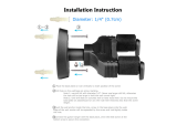
1.3, Installation Methods.
Indoor and outdoor domes can mount in a variety of ways (Fig-
ure l-2).
Indoor domes.
For “drop tile” ceilings, a dome housing is
available that fits standard 2 x 2 openings.
For sheet rock, wood, or ceilings with special finishes, a hard
ceiling housing is available. The 20mm lip of this housing en-
hances the appearance of the dome in well designed ceilings.
For indoor ceilings of 6m or more, a 38mm pipe is added to the
hard ceiling mount to form a pendant mount. The pipe and
housing are matte white, but can be painted to match decor.
Outdoor domes.
Outdoor domes are furnished with mounts
for poles or for the sides of buildings. The most popular is an
over-the-roof design that mounts to the parapet. This mount
offers two advantages: 1) the dome can look over the roof as
well as at the area around the building, and 2) the mount
enables the dome to swing in so it can be serviced from the
roof, eliminating the need for an expensive mechanical lift.
All mounts facilitate quick installation after site preparation,
enabling wiring to be done during rough building construction.
Once the CCTV system is turned on, the domes can then be
quickly installed to monitor the move-in and set-up of the facility.
1-6
SENSORVISION SpeedDome

Introduction
Figure l-2. SpeedDome housings-mounting options
Indoor SpeedDome Mountings
Pendant Mount
RHIPM
Hard Ceiling Mount
RHICM
* Note: There is also a corner mount adapter (RH170)
that can be added to RHOWM to mount on the
corner of a building wall.
Outdoor SpeedDome Mountings
Over Root
Mount
h
RHORM
.
Celling Mount
RHOCM
Wall Mount
RHOWM *
f--b
Pole Mount
RHOPM
Installation and Service Features
In alphabetical order:
l
Interchangeability.
Each dome can be easily discon-
nected and plugged into a new location.
l
Internationally Recognized Connectors.
Internation-
ally recognized connectors are used to connect composite
and video cables from the controller to the dome. The dome
address can be changed without cable disconnect
(powering down the dome).
l
Safety.
The SpeedDome meets all international regulatory
agency standards. Electrically, all SpeedDomes utilize low-
voltage Class 2 circuitry and cable connectors keyed to
eliminate electrical hazards during use. Mechanically,
indoor domes use safety chains to anchor the dome to
building structural members and a safety lanyard to retain
the chassis in its housing during servicing. Outdoor domes
also use guide wires to maintain their structural integrity.
l
Simple Disassembly.
Only a Phillips screwdriver is
required to disassemble each motor (2 screws), the slip ring
(2 screws), the camera (four screws), and each PC board (2
to 4 screws).
SENSORVISION SpeedDome 1-7

l
Snap-Hinge Chassis.
Two sets of spring-loaded locking
pins enable the light weight camera chassis to swing out of
its housing for servicing or to be removed entirely.
l
V-Lock Adjustment.
The SpeedDome eliminaies old
cumbersome V-lock procedures via a remote V-lock
adjustment that enables synchronization to the ac power
line by one person at the control console.
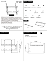
1.4 SPECIFICATIONS
See the following pages.
l-8
SENSORVISION
SpeedDome

Indoor SpeedDome Specifications
Monochrome (RAS585)lColor (RAS586)
U.S. Customary measurements in italics are rounded off.
Operational
Pan/Tilt Speed: .__._ - ............... .._._.~.~ .. 3” to 24” per second
(based on zoom position)
Pan Speed Multiplier:. .... ..-.-.- .. 2X, 3X, 4X
PanTravel: .............. .._.~.~.~....................~.~. 360”
Tilt Travel: -._.........._._._._.................-.-.-. >90”
Pan/Tilt Accuracy:
.............. .._._.~.~. f.5”
Zoom/ Focus Accuracy: ...... f.5%
Camouflage Lens
- Density: ........... ..__.I...........-~. ._-
........... 0.5f
- QuickView’“Time: ._.__________________ cl sec.
Auto Synchronization
- External: .. ..- ................. I ._._ ....................... 4/p-p composite sync/220Q
- Line Locked: .............. .._._ ................... Remote V-phase adjustment
- Internal:
Built-in sync generator
Memory Backup:
.. .._._ ...................... >24 hours
Address Range: .. .._._ ..................... ..~ l-99
Programmable Targets: .......... See System
Data Sheet
Programmable Patterns: ...... . 3
Alarm Inputs:
................ .._._....- ................ 4 dry contacts/3.5mA sink
Alarm Outputs: ....... ..-.-.-.-........-....- .- 4 open collector drivers
@ 12Vdc, 40mA
I Electrical
Primary Source: 16 to 36Vac, 50l60Hz
Power Consumption: - 20W max.
Power On
In-Rush Current:
4A for 112 cycle
Surge Protection
- Video Output:
1 OOA
- Power Line: 1200A
- Sync Input: Opto-isolated
- RS422 Comm. Line: -
1 OOA
- SensorNet Comm.
Line:
--___l_-
Isolation transformer
coupled
-Alarm Inputs:
100A
I Regulatory
Emissions:
Safety: .
FCC Part 15, Subpart B,
Class A
CISPR 22, Class B
ETL listed as:
UL1950, UL1409
CSA 22.2 No. 205-M1983,
CSA 22.2 No. 950
I Environmental
Operating Temperature:
-10°C to 50°C (14“F-722°F)
Relative Humidity: -.-..................... 0 to 95% non-condensing
I Mechanical
Pendant Mount - RHIPM
STD PIPE l-112’ 4 j
MAX 6.lm (20’).
F
1
I
202mm (8’)
EYEBALL DIA. -
190mm (7.5’)
t
356mm -
(14 7
I -T
102mm (4’)
2x2 Drop Tile Ceiling Mount - RHlW2
* 607mm c
Hard Ceiling Mount - RHICM
OPTIONAL
t
2OOmm (8’)
I
EYEBALL DIA.
190mm [7.5’) -i-
t-
394mm
-I
1
(15.5 ‘)
102mm (4’)
SENSORVISION
SpeedDome
1-9

Monochrome (RAS585) / Color (RAS586), continued
1
n
Camera
Monochrome/Color
Type: Interline transfer 1.27cm (l/2” )
CCD array
Scanning Area:
6.4
(H) x 4.8 (V) mm
Scanning System: ____
2: 1 interlace
Video Out:
1 .OVp-p/75Q composite
Signal-to-Noise: 48dB (typical)
Monochrome only
Horizontal Resolution: - 500 lines at center
Minimum Illumination: - 0.225 Iux at fl.2 (AGC on)
AGC:
>24dB
EIA
- Pickup Device: ___I
682 (H) x492 (V) pixels,
- Scanning: 525 lines, 60 fields, 30 frames
- Horizontal: 15.734kHz
- Vertical: 59.9Hz internal sync
CCIR
- Pickup Device: ~
681 (H) x 582 (V) pixels,
- Scanning: 625 lines, 50 fields, 25 frames
- Horizontal: 15.625kHz
- Vertical:
50Hz
Color only
Horizontal Resolution: - 430 lines at center
Minimum Illumination: - 2.25 Iux at fl.2 (AGC on)
White Balance: Through-the-lens (TTL) Auto
Tracing White balance (ATW)
NTSC
- Pickup
Device:
- Scanning:
- Horizontal:
- Vertical:
PAL
- Pickup
682 (H) x492 (V) pixels,
525 lines, 60 fields, 30 frames
15.734kHz
59.9Hz internal sync
Device: 681 (H) x 582 (V) pixels,
- Scanning:
625 lines, 50 fields, 25 frames
- Horizontal:
15.625kHz
- Vertical: 50Hz
I Lens
Focal Length: 8 to 80mm
Aperture: f 1 .2
Viewing Angle
- 8mm: ..-.-..
44.0”(H) x 33.3”(V)
- 80mm: ..-...
4.7”(H) x 3.5”(V)
Field-of-View Formulas:
6.4mm* x distance from camera (ft.)
focal length (mm)
= Hor. view (ft.)
4.8mmT x distance from camera (ft.)
focal length (mm)
= Vert. view (ft.)
*Horizontal scanning area of pickup device in this camera.
tvertical scanning area of pickup device in this camera.
Example of a wide angle view of a 8
to 80mm lens at 3.05m (703:
6.4mm x 10 ft.
8mm
= 8ft. horizontal view
4.8mm x 10 ft.
= 6ft. vertical view
8mm
l-10 SENSORVISION
SpeedDome

Outdoor SpeedDome Specifications
Monochrome (RAS285)lColor (RAS286)
U.S. Customary measurements in italics are rounded off.
I Operational
Pan/Tilt Speed: 2” to 18” per second for
12-120mm focal length
3” to 24” per second for
8-180mm focal length
(based on zoom position)
Pan Speed Multiplier: - 2x, 3x, 4x
PanTravel: 360”
Tilt Travel: SO”
Pan/Tilt Accuracy: ____ lt.5”
Zoom/ Focus Accuracy: - +.5%
Camouflage Lens
- Density: 0.5f
- QuickView’“Time: ~ 11 sec.
Auto Synchronization
- External: ___- 4Vp-p composite sync/220R
- Line Locked: Remote V-lock adjustment
- Internal:
Built-in sync generator
Memory Backup:
>24 hours
Address Range: 1-99
Programmable Targets: - See System Data Sheet
Programmable Patterns: - 3
Alarm Inputs: 4 dry contactsl3.5mA sink
Alarm Outputs: 4 open collector drivers
@ 12 Vdc, 40 mA
I Electrical
Primary Source: I .-.-.-.-..................... 21 to 36Vac, 50/60Hz
Power Consumption: ..-.. 130W max.
Surge Protection
Video Output: _.._.............__... 5,OOOA
Power Line: ._._______._________.~.~.~.. 5,OOOA
Sync Input: ..-.- .._..__..__... -._-.-._ 5,00OA*
RS422 Comm. Line: -.... 5,000A
Alarm Inputs: ____________._._._._.~.~ 5,00OA*
“Requires RS422 Surge Protector (p/n 4815-0021-01).
I Regulatory
Emissions: - FCC Part 15, Subpart B,
Class A
VDE 0871, Class B
CISPR 22, Class B
Safety: ETL listed as:
UL1950, ULI 409
CSA 22.2 No. 205-M1983,
CSA 22.2 No. 950
CENELEC EN60950
Mechanical
Over Roof Mount - RHORM
2’ ST0 PIPE FITTING
Ceiling Mount - RHOCM
1-W MOUNTING
Pole Mount - RHOPM
ROUND OR SOUARE POLE FROM
IOOmm (3.9) TO 305mm (lr)
1-W STD PIPE
,, I-1/2’STD PIPE FITTING
Wall Mount - RHOWM
1-W STD PIPE
,, 1-W ST0 PIPE FITTING
395mm (15.6’)
Optional Comer
Bracket Mount - RH170
(top view)
SENSORVISION
SpeedDome
l-11

Monochrome (RAS285) / Color (RAS286), continued
1
n
Camera
I Lens (with Spot Filter)
Monochrome/Color
Type: . Interline transfer 1.27cm (l/2”)
CCD array
Scanning Area: -- 6.4 (H) x 4.8 (V) mm
Scanning System: ____ 2:l interlace
Video Out: 1 .OVp-p/75R composite
Signal-to-Noise: -- 48dB (typical)
Monochrome only
Horizontal Resolution: 500 lines at center
Minimum Illumination: -........ 0.22 Iux at fl.2
(8-80mm, AGC on)
0.5 Iux at fl.8
(12-l 20mm, AGC on)
AGC: .._.____.___________.~..............~.~.~..............~. >24dB
EIA
- Pickup Device: ..-.-.--............-. 682 (H) x492 (V) pixels,
- Scanning: .__._.________.___._....~...........~.
525 lines, 60 fields, 30 frames
- Horizontal: _._.___________._._.~...........~. 15.734kHz
- Vertical: . .._______._._______.....~.~.~.............. 59.9Hz internal sync
CCIR
- Pickup Device: ..-.-.-.............. 681 (H) x 582 (V) pixels,
- Scanning: ._____.___________._.~.~ - __________. 625 lines, 50 fields, 25 frames
- Horizontal: _._.__._________._._.~.............. 15.625kHz
- Vertical: __________._ - _______.__._._._.___.......... 5OHz
Color only
Horizontal Resolution: -.-.... 430 lines at center
Minimum Illumination: .-.-... 2.25 lux at f1.2, (8-80mm
AGC on)
5 Iux at fl.8, (12-120mm
AGC on)
White Balance: ..-.-....-........-....- Through-the-lens (TTL) Auto
Tracing White balance (ATW)
NTSC
- Pickup Device: .-..............-.-.-.. 682 (H) x492 (V) pixels,
- Scanning: _.___________._._.__.~........~.~.~.. 525 lines, 60 fields, 30 frames
- Horizontal: ____.__.~._.__._.___....~....~.~.. 15.734kHz
- Vertical: _._._________.._._._........~.~.~.~........ 59.9Hz internal sync
PAL
- Pickup Device: .._._..............~. 681 (H) x 582 (V) pixels,
- Scanning: .__.__._._________._.~.~~............~. 625 lines, 50 fields, 25 frames
- Horizontal: _ . .._.___._.___.........-.-. 15.625kHz
- Vertical: __.__._.__._____.___.~.~....~..~....~.~. 5OHz
Long Lens Extended Lens
Focal Length: - 8 to 80mm _._.____________ - _._._____ 12 to 12Omm
Aperture: - f1.2 ._________________...~.~....~..~.~.~.~.... f1.8
Viewing Angle
Wide.
. ._._ ._ .._
44.0”(H) x 33.3”(V) ..-. 29.8”(H) x 22.6”(V)
Tele: -.-....-.- 4.7”(H) x 3.5”(V) -........... 3.0”(H) x 2.3”(V)
Field=of-View Formulas:
6.4mm* x distance from camera (ft.)
focal length (mm)
= Hor. view (ft.)
4.8mmt x distance from camera (ft.)
focal length (mm)
= Vert. view (ft.)
*Horizontal scanning area of pickup device in this camera.
TVertical scanning area of pickup device in this
camera.
Example of a wide angle view of a 8
to 80mm lens at 3.05m (70’J:
6.4mm x 10 ft.
8mm
= 8ft. horizontal view
4.8mm x 10 ft.
= 6ft. vertical view
8mm
n
Environmental
Operating Temperature: - -40°C to 50°C (-40°f-1220F)
Relative Humidity: ~ 0 to 95% non-condensing
Storage Temperature: -
-20°C to 65°C (--4”F-149°F)
Wind Loading
Wall1 Mount, Pole
Mount *, & Over-the-
Roof Mount with
Guidewires:
241 km/hr (150 miles/hr)
sustained winds. f. 125”
Over-the-Roof
Mount without
video oscillation’at 48 km/hr
(30 miles/hr) in gusting wind
Guidewires: _.__.____.__________.........~.~ 177 km/hr (1 10 miles/hr)
sustained winds, f. 125”
video oscillation at 24
km/hr (15 miles/hr) in
gusting wind
*Assumes mounting on a rigid pole.
1-12 SENSORVISION Speed&me

2.1 BEFORE YOU BEGIN
2.1.1
Verifying and Unpacking Equipment
l
Verify that all equipment has arrived.
l
Verify that the unit shipped is the correct configuration for
the site.
l
Be organized.
l
Unpack components in a back room.
l
At the installation area, lay out parts in the order you will
need them.
l
Do not clutter traffic areas or cause a trip hazard.
2.1.2
Planning the installation
First, carefully detail the system’s layout. Before acquiring
equipment, designate a representative to coordinate installation
planning activities. Through close interaction with the planner
and customer at the site, mark the precise locations of the
domes on a blueprint of the facility. With the blueprint, a pre-
installation site survey should be conducted with special
installation considerations noted.
Upon equipment and cabling delivery to the site, review the
blueprints and site survey with the facility and loss prevention
managers. This will ensure that nothing has changed and that
everyone is in agreement with the system layout.
SENSORVISION SpeedDome 2-1

2.2 SAFETY PRECAUTIONS
A WARNING A
Observe the following common sense
precautions for your own safety:
ALWAYS USE:
l
Proper safety equipment for the location
and type of installation.
l
Proper lift equipment to reach the point
of installation.
l
Safety features of the lift equipment.
BE SURE:
l
Electrical power is not connected to the
product during installation or to any object
that you might contact during installation.
2.3
iNDOOR MOUNTBNG
METHODS
This sub-section consists of Quick Reference Sheets Q-l
through Q-9 and Q-18 through Q-20.
2.4 OUTDOOR MOUNTING
METHODS
This sub-section consists of Quick Reference Sheets Q-10
through Q-20.
2.5
ADDITIONAL INFORMATION
This chapter covers SpeedDome installation and control via
RS422 communications. Refer to Appendixes A and B, located
at the back of this manual, for installation information on
connecting SpeedDome to American Dynamics equipment, and
SpeedDome installation and control via SensorNet.
2-2
SENSORVISION
SpeedDome

- Indoor Hard Ceiling Mount - RHICM
Method II - Installation without adjustable bracket
Reauired Parts
Hard bount Kit
0351-0393-01 (part of 0200-0178-01, which
ships with RHICM).
Description Qty. Part No.
“S” hook, open 2 2897-0004
Chain, Navy link 6 2898-0002
Eye bolt, IO-24 w/nut
1 2882-0112
A
Washer, flat, SS #lO
2 2848-8100-l 7
Nut, locking, 10x24 1 2838-9154-05
Aluminum tape 4Fr 3200-0115-01
FOR ALL CEILINGS
EXCEPT TILE.
CEILINGS MUST BE
ABLE TO HOLD m
LEdST 9kg (20 NM)!
i
20cn
037
T
1
IMPORTANT: Shipping box contains a
template-do not throw the template out.
1.
Using the template, scribe a 356cm
(74”)* hole in the ceiling or tile. Cut out
the hole.
2.
Place a washer [a] over the eyebolt
supplied [b]. Insert the eyebolt into a
hole in the top of the housing and
secure using a washer and nut [cl.
*U.S. Customary Measurements in italics are rounded off.
3.
Using an S-hook, hang safety chain [d]
from a strong ceiling member and, using
a second S-hook, attach other end of the
chain to the eyebolt. Keep the chain as
taut as possible. Tighten both ends of
each S-hook.
A
KEEP CHAIN
AS
TAUT AS
POSSIBLE! CLOSE ENDS OF
EACH S-HOOK!
DO NOT USE SPRINKLER OR
FIRE CONTROL SYSTEM FOR
SECURING THE SAFETY CHAIN!
Feed video and multiconductor cables [e]
through one of the two holes in the side of
the housing. Then cover all openings in
the housing with the aluminum tape
supplied.
5.
With the three mounting tabs [f] of the
housing in the up position, insert the
housing into the ceiling hole, then from
inside the housing bring the tabs down
and tighten their screws to secure. The
housing is now ready for chassis
installation (page Q-8).
SENSORVISION SpeedDome Q-l
/