ELICA EOR627SS Install Guide (9.54MB)
- Category
- Cooker hoods
- Type
- Install Guide (9.54MB)

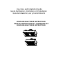
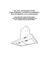
Use, Care, and Installation Guide
Guide d’utilisation, d’entretien et d’installation
Guía de instalación, uso y mantenimiento
READ AND SAVE THESE INSTRUCTIONS
LISEZ CES INSTRUCTIONS ET CONSERVEZ-LES
READ AND SAVE THESE INSTRUCTIONS

English
Contents page 2
French
Sommaire page 15
Spanish
Contenido página 29
English
Contents
Important safety Notice..............................................................................................................................................3
Electrical & Installation requirements ......................................................................................................................4
Electrical requirements ........................................................................................................................................................................................ 4
Before installing the hood .................................................................................................................................................................................... 4
List of Materials...........................................................................................................................................................5
Parts supplied......................................................................................................................................................................................................5
Parts not supplied................................................................................................................................................................................................5
Dimensions and Clearances......................................................................................................................................6
Ducting Options and Examples.................................................................................................................................7
Venting methods.................................................................................................................................................................................................. 7
Preparation .......................................................................................................................................................................................................... 7
Installation...................................................................................................................................................................8
Installation - Ducting version................................................................................................................................................................................ 8
Description of the hood & Controls........................................................................................................................11
Controls.............................................................................................................................................................................................................. 12
Maintenance..............................................................................................................................................................13
Cleaning............................................................................................................................................................................................................. 13
Grease Filter......................................................................................................................................................................................................13
Replacing the light bulb......................................................................................................................................................................................13
Warranty ....................................................................................................................................................................14
APPROVED FOR RESIDENTIAL APPLIANCES
FOR RESIDENTIAL USE ONLY
READ AND SAVE THESE INSTRUCTIONS
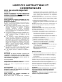
PLEASE READ ENTIRE INSTRUCTIONS BEFORE PROCEEDING.
INSTALLATION MUST COMPLY WITH ALL LOCAL CODES.
IMPORTANT: Save these Instructions for the Local Electrical Inspector’s use.
INSTALLER: Please leave these Instructions with this unit for the owner.
OWNER: Please retain these instructions for future reference.
Safety Warning: Turn off power circuit at service panel and lock out panel, before wiring this appliance.
Requirement: 120 V AC, 60 Hz. 15 or 20 A Branch Circuit

3
READ AND SAVE THESE INSTRUCTIONS
Important safety Notice
CAUTION
FOR GENERAL VENTILATING USE ONLY. DO NOT USE
TO EXHAUST HAZARDOUS OR EXPLOSIVE
MATERIALS OR VAPOURS.
WARNING
TO REDUCE THE RISK OF FIRE, ELECTRIC SHOCK, OR
INJURY TO PERSONS, OBSERVE THE FOLLOWING:
A. Use this unit only in the manner intended by the
manufacturer. If you have questions, contact the
manufacturer.
B. Before servicing or cleaning the unit, switch power off at
service panel and lock service panel disconnecting
means to prevent power from being switched on
accidentally. When the service disconnecting means
cannot be locked, securely fasten a prominent warning
device, such as a tag, to the service panel.
C. Installation Work and Electrical Wiring Must Be Done By
Qualified Person(s) In Accordance With All Applicable
Codes & Standards, Including Fire-rated Construction.
D. Sufficient air is needed for proper combustion and
exhausting of gases through the flue (Chimney) of fuel
burning equipment to prevent back- drafting. Follow the
heating equipment manufacturers guideline and safety
standards such as those published by the National Fire
Protection Association (NFPA), the American Society for
Heating, Refrigeration and Air Conditioning Engineers
(ASHRAE), and the local code authorities.
E. When cutting or drilling into wall or ceiling, do not
damage electrical wiring and other hidden utilities.
F. Ducted systems must always be vented to the outdoors.
CAUTION
To reduce risk of fire and to properly exhaust air, be
sure to duct air outside - do not vent exhaust air into
spaces within walls, ceilings, attics, crawl spaces, or
garages.
WARNING
TO REDUCE THE RISK OF FIRE, USE ONLY METAL
DUCT WORK.
Install this hood in accordance with all requirements
specified.
WARNING
To Reduce The Risk Of Fire Or Electric Shock, Do Not
Use This Hood With Any External Solid State Speed
Control Device.
WARNING
TO REDUCE THE RISK OF A RANGE TOP GREASE FIRE.
a) Never leave surface units unattended at high settings.
Boilovers cause smoking and greasy spillovers that may
ignite. Heat oils slowly on low or medium settings.
b) Always turn hood ON when cooking at high heat or when
flambeing food (I.e. Crepes Suzette, Cherries Jubilee,
Peppercorn Beef Flambe’).
c) Clean ventilating fans frequently. Grease should not be
allowed to accumulate on fan or filter.
d) Use proper pan size. Always use cookware appropriate
for the size of the surface element.
WARNING
TO REDUCE THE RISK OF INJURY TO PERSONS, IN
THE EVENT OF A RANGE TOP GREASE FIRE,
OBSERVE THE FOLLOWING:
a) SMOTHER FLAMES with a close-fitting lid, cookie sheet,
or other metal tray, then turn off the gas burner or the
electric element. BE CAREFUL TO PREVENT BURNS.
If the flames do not go out immediately, EVACUATE
AND CALL THE FIRE DEPARTMENT.
b) NEVER PICK UP A FLAMING PAN - you may be burned.
c) DO NOT USE WATER, including wet dishcloths or
towels - a violent steam explosion will result.
d) Use an extinguisher ONLY if:
1) You know you have a class ABC extinguisher, and you
already know how to operate it.
2) The fire is small and contained in the area where it
started.
3) The fire department is being called.
4) You can fight the fire with your back to an exit.
OPERATION
a. Always leave safety grills and filters in place. Without
these components, operating blowers could catch onto hair,
fingers and loose clothing.
The manufacturer declines all responsibility in the event of
failure to observe the instructions given here for installation,
maintenance and suitable use of the product. The
manufacturer further declines all responsibility for injury due
to negligence and the warranty of the unit automatically
expires due to improper maintenance.
CAUTION
Automatically Operated Device - To Reduce The Risk Of
Injury Disconnect From Power Supply Before Servicing.
This unit is equipped with integral disconnecting switch
located inside the blower housing.

4
Electrical & Installation requirements
Electrical requirements
IMPORTANT
Observe all governing codes and ordinances.
It is the customer’s responsibility:
To contact a qualified electrical installer.
To assure that the electrical installation is adequate and in
conformance with National Electrical Code, ANSI/NFPA 70
— latest edition*, or CSA Standards C22.1-94, Canadian
Electrical Code, Part 1 and C22.2 No.0-M91 - latest
edition** and all local codes and ordinances.
If codes permit and a separate ground wire is used, it is
recommended that a qualified electrician determine that the
ground path is adequate.
Do not ground to a gas pipe.
Check with a qualified electrician if you are not sure range
hood is properly grounded.
Do not have a fuse in the neutral or ground circuit.
IMPORTANT
Save Installation Instructions for electrical inspector’s use.
The range hood must be connected with copper wire only.
The range hood should be connected directly to the fused
disconnect (Or circuit breaker) box through metal electrical
conduit.
Wire sizes must conform to the requirements of the National
Electrical Code ANSI/NFPA 70 — latest edition*, or CSA
Standards C22.1-94, Canadian Electrical Code Part 1 and
C22.2 No. 0-M91 - latest edition** and all local codes and
ordinances.
A U.L.- or C.S.A.-listed conduit connector must be provided
at each end of the power supply conduit (at the range hood
and at the junction box).
Copies of the standards listed may be obtained from:
* National Fire Protection Association Batterymarch Park Quincy,
Massachusetts 02269
** CSA International 8501 East Pleasant Valley Road Cleveland,
Ohio 44131-5575
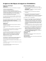
Before installing the hood
1. For the most efficient air flow exhaust, use a straight run
or as few elbows as possible.
CAUTION: Vent unit to outside of building, only.
2. At least two people are necessary for installation.
3. Fittings material is provided to secure the hood to most
types of walls/ceilings, consult a Qualified Installer,
check if they perfectly fit with your cabinet/wall.
4. Do not use flex ducting.
5. COLD WEATHER installations should have an additional
backdraft damper installed to minimize backward cold air
flow and a nonmetallic thermal break to minimize
conduction of outside temperatures as part of the
ductwork. The damper should be on the cold air side of
the thermal break.
The break should be as close as possible to where the
ducting enters the heated portion of the house.
6. Make up air: Local building codes may require the use of
Make-Up Air Systems when using Ducted Ventilation
Systems greater than specified CFM of air movement.
The specified CFM varies from locale to locale. Consult
your HVAC professional for specific requirements in your
area.
Removing the packaging
CAUTION!
Remove carton carefully, Wear gloves to protect against
sharp edges.
WARNING!
Remove the protective film covering the product before
putting into operation.

5
List of Materials
Parts supplied
Removing the packaging
CAUTION!
Remove carton carefully, Wear gloves to protect against
sharp edges.
WARNING!
Remove the protective lm covering the product before
putting into operation.
• Integral blower housing
• Integral blower
• Grease lters supporting frame
• Filter trim bracket (33" & 45” model only)
• Transition
• Lamp already installed
• Grease lters
• Hardware bag with:
• Use, care and installation guide
• 10 Wood screws
• 4 Assembly screws (for Transition)
• 2 assembly screws (for integral blower spring clip)
• 6 assembly screws (for grease lters supporting
frame)
• 1 spring clip (for integral blower installation)
• 2 machine screws (for integral blower installation)
•
2 knobs for lter trim bracket (33" & 45” model only)
Parts not supplied
Optional Accessories
• Hood liner
Tools/Materials required
• Wire nuts
• 10" rounded metal duct length to suit installation
• Measuring tape
• Pliers
• Gloves
• Knife
• Safety glasses
• Strain relief
• Spirit level
• Duct tape
• Screwdrivers:
Phillips (Posidrive) # 2
• Wire cutter/stripper
• Masking tape
• Saw, jig saw or reciprocating saw

6
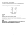
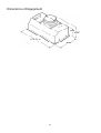
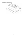
Dimensions and Clearances
27”- 33”- 39”- 45”

7
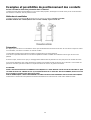
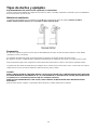
Ducting Options and Examples
Closely follow the instructions set out in this manual.
All responsibility, for any eventual inconveniences, damages or fires caused by not complying with the instructions in this
manual, is declined.
Venting methods
The hood is equipped with a transition B for discharge of fumes to the outside (Ducting version).
Minimum Duct Size (Ducting/Ductless version): 10" Round Pipe.
Preparation
Do not cut a joist or stud unless absolutely necessary. If a joist or stud must be cut, then a supporting frame must be
constructed.
Fittings material is provided to secure the hood to most types of walls/ceilings.
However, a qualified technician must verify suitability of the materials in accordance with the type of wall/ceiling.
Before making cutouts, make sure there is proper clearance within the ceiling or wall for exhaust vent.
Hood installation height above cooktop is the users preference. The lower the hood is above the cooktop, the more efficient the
capturing of cooking odors, grease and smoke.
CAUTION:
FOR ELECTRIC AND GAS RANGES INSTALLATION: MOUNT THIS HOOD SO THAT THE BOTTOM EDGE IS NOT LESS
THAN 30" (76,2 CM) ABOVE THE COOKING SURFACE (height measured from the cooktop to the lowest part of the
Hood).
HOUSEHOLD USE. PLEASE, READ INSTALLATION MANUAL FOR SPECIFIC APPLICATION.
Check your ceiling height and the hood height maximum before you select your hood.

8
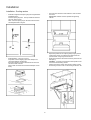
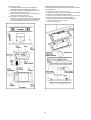
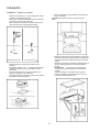
Installation
Installation - Ducting version
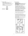
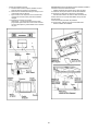
• Install the integral blower spring clip (for integral blower
installation only):
Insert the spring clip from the top outside of the hood
and x it with 2 screws.
Note: Insert the spring clip on the slot located close to
the integral blower xing nut.
• Install transition onto top of hood:
Important: remove shipping tape from damper and
check that damper moves freely.
Place the transition over the exhaust hole of the hood
and secure with 4 screws.
Tape to seal connection and check that damper moves
freely.
• Cut a hole in the bottom of the cabinet in order to settle
the hood.
IMPORTANT- Cabinet must be capable of supporting
100 lbs.
• Adjust the position of the clasping side spring by means
of the proper screw, according to the thickness of the
panel to which it is going to be anchored.
• Insert the hood in the cabinet and lock it by means of the
side spring.
WARNING: 2 people are required to lift and position the
hood onto the mounting screws.
• Use the holes in the casing of the hood to attach it using
8 mounting screws 27”-33” or 10 mouting screws 39”- 45”.

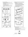
9
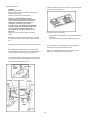
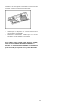
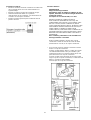
• Install the integral blower:
a. From the inside of the hood, slip motor into the
attachment slot on the left.
b. Rotate motor upwards until it snaps into the spring
clip on the right.
c. Secure the motor to the hood with 2 machine screws
on integral blower xing nuts.
d. Plug connector into the motor.
Important: Connector ends are designed to mate
only one way. Match at and round connectors as
shown.
• Install the grease lters supporting frame:
a. lift the frame to cover the blower housing.
b. Secure it to the body of the hood with 6 screws.
• 33" & 45” model only: Install the Filter trim bracket
in the mid of the grease lter suppeorting frame:
a. First frontwards, inserting the tabs
b. Then rearwards using 2 knobs supplied
Connecting the ductwork
• Install ductwork, making connections in the direction of
airow as illustrated.
• Push duct over the exhaust outlet.
• Wrap all duct joints and the ange connections with duct
tape for an airtight seal.
• Make the same connection in the wall or ceiling vent exit.
IMPORTANT: Remove the light bulbs before installing
the supporting frame. Refer to the maintenance section
for instructions.
• Re- install the light bulbs.

10
Electrical connection
WARNING
Electrical Shock Hazard
Warning: Turn o power circuit at the service panel
before wiring this unit.
120 VAC, 15 or 20 Amp circuit required.
ELECTRICAL GROUNDING INSTRUCTIONS
THIS APPLIANCE IS FITTED WITH AN ELECTRICAL
JUNCTION BOX WITH 3 WIRES, ONE OF WHICH
(GREEN/YELLOW) SERVES TO GROUND THE
APPLIANCE. TO PROTECT YOU AGAINST
ELECTRIC SHOCK, THE GREEN AND YELLOW WIRE
MUST BE CONNECTED TO THE GROUNDING WIRE
IN YOUR HOME ELECTRICAL SYSTEM, AND IT
MUST UNDER NO CIRCUMSTANCES BE CUT OR
REMOVED.
Failure to do so can result in death or electrical
shock.
Remove the knockout and the Junction box cover and
install the conduit connector (cULus listed) in junction
box.
• If not already done, install 1/2” conduit connector in j-box.
Run 3 wires; black, white and green ,according to the
National Electrical Code and local codes and ordinances,
in 1/2" conduit from service panel to junction box.
Connect black wire from service panel to black or red in
junction box, white to white and green to green-yellow.
Close and secure junction box cover.
Install the grease lter and turn power on at service panel.
Check operation of the hood.
If range hood does not operate:
• Check that the circuit breaker is not tripped or the house
fuse blown.
• Disconnect power supply. Check that wiring is correct.
To get the most ecient use from your new range hood,
read the “Use and Care Information” section.
Keep your Installation Instructions and Use and Care
Guide close to range hood for easy reference.
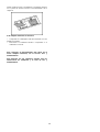
45”
27”-33”-39”

11
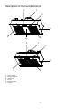
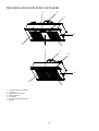
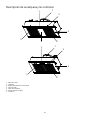
Description of the hood & Controls
1. Blower and light controls
2. Lamp housings
3. Grease lter Handle
4. Grease lter
5. Canopy
6. Grease lters trim
7. Transition
1
1
2
2
3
3
4
4
5
5
6
7
7

12
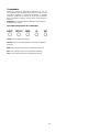
Controls
Use the high suction speed in cases of concentrated kitchen
vapours. It is recommended that the cooker hood suction is
switched on for 5 minutes prior to cooking and to leave in
operation during cooking and for another 15 minutes
approximately after terminating cooking.
Note: Hood retains last speed setting when aspiration
switch is turned off.
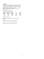
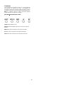
Description of control panel
LIGHT: on/off light switch
OFF/LO: on/off aspiration switch and minimum power
selection
MED: medium power selection aspiration switch
HI: maximum power selection aspiration switch
INT: intensive power selection aspiration switch

13
Maintenance
ATTENTION! Before performing any maintenance operation, isolate the hood from the electrical supply by switching o at the
connector and removing the connector fuse.
Or if the appliance has been connected through a plug and socket, then the plug must be removed from the socket.
Cleaning
Do not spray cleaners directly to the control while
cleaning the Hood. The cooker hood should be cleaned
regularly (at least with the same frequency with which you
carry out maintenance of the fat lters) internally and
externally. Clean using the cloth dampened with neutral
liquid detergent. Do not use abrasive products. DO NOT
USE ALCOHOL!
WARNING:
Failure to carry out the basic cleaning recommendations of
the cooker hood and replacement of the lters may cause
re risks.
Therefore, we recommend oserving these instructions.
The manufacturer declines all responsibility for any damage
to the motor or any re damage linked
to inappropriate
maintenance or failure to observe the above safety
recommendations.
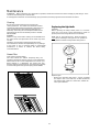
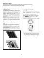
Grease Filter
Traps cooking grease particles.
The lters should be washed frequently using non
aggressive detergents, either by hand or in the dishwasher,
which must be set to a low temperature and a short cycle.
When washed in a dishwasher, the grease lter may
discolour slightly, but this does not aect its ltering capacity.
To remove the grease lter, pull the spring release handle.
Replacing the light bulb
CAUTION
Before replacing the lamps, switch power o at service
panel and lock service panel disconnecting means to
prevent power from being switched on accidentally.
NOTE: Turn o the lights and fan. Allow the lights to
cool
before handling. If new lights do not operate be
sure lights are inserted correctly before calling service.
Replace Lights
• Remove the damaged light (twist counter clockwise)
and replace with a new 120 Volt, 50 Watt (maximum)
50° halogen light made for a GU10 base, suitable for
use in open luminarie.

14
TO OBTAIN SERVICE UNDER WARRANTY
Owner must present proof of original purchase date. Please keep a copy of your dated proof of
purchase (sales slip) in order to obtain service under warranty.
PARTS AND SERVICE WARRANTY
For the period of two (2) years from the date of the original purchase, Elica will provide free of charge,
non consumable parts or components that failed due to manufacturing defects. During these two (2)
years limited warranty, Elica will also provide free of charge, all labor and in-home service to replace any
defective parts.
WHAT IS NOT COVERED
• Damage or failure to the product caused by accident or act of God, such as, ood, re or earthquake.
• Damage or failure caused by modication of the product or use of non-genuine parts.
• Damage or failure to the product caused during delivery, handling or
installation.
• Damage or failure to the product caused by operator abuse.
• Damage or failure to the product caused by dwelling fuse replacement or resetting of circuit breakers.
• Damage or failure caused by use of product in a commercial application.
• Service trips to dwelling to provide use or installation guidance.
• Light bulbs, metal or carbon lters and any other consumable part.
• Normal wear of nish.
• Wear to nish due to operator abuse, improper maintenance, use of corrosive or abrasive cleaning
products/pads and oven cleaner products.
WHO IS COVERED
This warranty is extended to the original purchaser for products purchased for ordinary residential use in
North America (Including the United States, Guam, Puerto Rico, US Virgin Islands & Canada).
This warranty is non-transferable and applies only to the original purchaser and does not extend to
subsequent owners
of the product. This warranty is made expressly in lieu of all other warranties,
expressed or implied, including, but not limited to any implied warranty of merchantability or tness for a
particular purpose and all other obligations on the part of Elica North America, provided, however, that if
the disclaimer of implied warranties is ineectiv e under applicable law, the duration of any implied
warranty arising by operation of law shall be limited to two (2) years from the date of original purchase at
retail or such longer period as may be required by applicable law.
This warranty does not cover any special, incidental and/or consequential damages, nor loss of prots,
suered by the original purchaser, its customers and/or the users of the Products.
WHO TO CONTACT
To obtain Service under Warranty or for any Service Related Question
Please Call:
•
Elica North America Authorized Service at (888) 732-8018
Or by Writing To:
• Elica North America, Attention Customer Service, 222 Merchandise Mart Plaza Suite 947,
Chicago, IL 60654 USA
Warranty
TWO-YEARSLIMITED WARRANTY
ELICA North America
Page is loading ...
Page is loading ...
Page is loading ...
Page is loading ...
Page is loading ...
Page is loading ...
Page is loading ...
Page is loading ...
Page is loading ...
Page is loading ...
Page is loading ...
Page is loading ...
Page is loading ...
Page is loading ...
Page is loading ...
Page is loading ...
Page is loading ...
Page is loading ...
Page is loading ...
Page is loading ...
Page is loading ...
Page is loading ...
Page is loading ...
Page is loading ...
Page is loading ...
Page is loading ...
Page is loading ...
Page is loading ...
Page is loading ...

Printed in Mexico
LI3FBA Ed. 04/08
-
 1
1
-
 2
2
-
 3
3
-
 4
4
-
 5
5
-
 6
6
-
 7
7
-
 8
8
-
 9
9
-
 10
10
-
 11
11
-
 12
12
-
 13
13
-
 14
14
-
 15
15
-
 16
16
-
 17
17
-
 18
18
-
 19
19
-
 20
20
-
 21
21
-
 22
22
-
 23
23
-
 24
24
-
 25
25
-
 26
26
-
 27
27
-
 28
28
-
 29
29
-
 30
30
-
 31
31
-
 32
32
-
 33
33
-
 34
34
-
 35
35
-
 36
36
-
 37
37
-
 38
38
-
 39
39
-
 40
40
-
 41
41
-
 42
42
-
 43
43
-
 44
44


ELICA EOR627SS Install Guide (9.54MB)
- Category
- Cooker hoods
- Type
- Install Guide (9.54MB)
Ask a question and I''ll find the answer in the document
Finding information in a document is now easier with AI
in other languages
- français: ELICA EOR627SS
- español: ELICA EOR627SS
Related papers
-
ELICA Twin Optica Installation guide
-
-
-
-
-
-
-
ELICA ECL630S4 Installation guide
-
-
ELICA EPL636S1 Installation guide
Other documents
-
Zephyr GU4/MR11 Installation guide
-
-
 arietta DKW001MX36 Installation guide
-
Frigidaire PLHV36W7KC User manual
-
Electrolux EJIB369TDJS User manual
-
-
Fujioh BUF-06E User manual
-
Frigidaire Ventilation Hood PLHV42P8KC User manual
-
Thermador HPWB36FS Installation guide
-
Thermador HPWB30FS Installation guide
