Page is loading ...

May 2021 www.lxnav.com
INSTALLATION MANUAL
LXNAV RS485/CAN
Remote
Control stick
Version 1.11

Rev #6 Version 1.11 May 2021
Page 2 of 15
1 Important Notices ................................................................................... 3
1.1 Limited Warranty ....................................................................................... 3
2 Packing list .............................................................................................. 4
2.1 RS485 (LX90x0, LX80x0) ........................................................................... 4
2.2 CAN (S8x, S10x) ........................................................................................ 4
3 Technical Data ......................................................................................... 5
4 Versions ................................................................................................... 6
4.1 Functionality .............................................................................................. 6
4.2 Diameter of command handles .................................................................. 6
4.3 Shapes ....................................................................................................... 6
5 Installation .............................................................................................. 7
5.1 Power and communication wiring ............................................................. 7
5.1.1 RS485 (LX90x0, LX80x0) ............................................................................. 8
5.1.2 CAN (S8x, S10x) ......................................................................................... 9
5.2 Push to talk – PTT .................................................................................... 10
5.3 Speed command – SC .............................................................................. 10
5.4 Wiring of function switches ..................................................................... 10
5.4.1 Trim switch .............................................................................................. 10
5.4.2 Starter button........................................................................................... 10
6 Functions ............................................................................................... 11
6.1 RS485 (LX90x0, LX80x0) ......................................................................... 11
6.2 CAN (S8x, S10x) ...................................................................................... 12
7 Dimensions ............................................................................................ 13
7.1 Normal insert ........................................................................................... 13
7.2 Slanted insert .......................................................................................... 13
7.2.1 Mounting screws (DIN 916/ISO 4029 M 3 x 6) ............................................ 13
8 Revision history ..................................................................................... 14

Rev #6 Version 1.11 May 2021
Page 3 of 15
1 Important Notices
The LXNAV CAN Remote is designed for VFR use only. All information is presented for reference
only. It is ultimately the pilot's responsibility to ensure the aircraft is being flown in accordance
with the manufacturer's aircraft flight manual. The LXNAV CAN Remote must be installed in
accordance with applicable airworthiness standards according to the country of registration of
the aircraft.
Information in this document is subject to change without notice. LXNAV reserves the right
to change or improve their products and to make changes in the content of this material
without obligation to notify any person or organisation of such changes or improvements.
A Yellow triangle is shown for parts of the manual which should be read carefully
and are important for operating the system.
Notes with a red triangle describe procedures that are critical and may result in loss
of data or any other critical situation.
A bulb icon is shown when a useful hint is provided to the reader.
1.1 Limited Warranty
This LXNAV CAN Remote product is warranted to be free from defects in materials or
workmanship for two years from the date of purchase. Within this period, LXNAV will, at its
sole option, repair or replace any components that fail in normal use. Such repairs or
replacement will be made at no charge to the customer for parts and labour, the customer
shall be responsible for any transportation cost. This warranty does not cover failures due to
abuse, misuse, accident, or unauthorised alterations or repairs.
THE WARRANTIES AND REMEDIES CONTAINED HEREIN ARE EXCLUSIVE AND IN LIEU OF ALL
OTHER WARRANTIES EXPRESSED OR IMPLIED OR STATUTORY, INCLUDING ANY LIABILITY
ARISING UNDER ANY WARRANTY OF MERCHANTABILITY OR FITNESS FOR A PARTICULAR
PURPOSE, STATUTORY OR OTHERWISE. THIS WARRANTY GIVES YOU SPECIFIC LEGAL
RIGHTS, WHICH MAY VARY FROM STATE TO STATE.
IN NO EVENT SHALL LXNAV BE LIABLE FOR ANY INCIDENTAL, SPECIAL, INDIRECT OR
CONSEQUENTIAL DAMAGES, WHETHER RESULTING FROM THE USE, MISUSE, OR INABILITY
TO USE THIS PRODUCT OR FROM DEFECTS IN THE PRODUCT. Some states do not allow the
exclusion of incidental or consequential damages, so the above limitations may not apply to
you. LXNAV retains the exclusive right to repair or replace the unit or software, or to offer a
full refund of the purchase price, at its sole discretion. SUCH REMEDY SHALL BE YOUR SOLE
AND EXCLUSIVE REMEDY FOR ANY BREACH OF WARRANTY.
To obtain warranty service, contact your local LXNAV dealer or contact LXNAV directly.
May 2021 © 2021 LXNAV. All rights reserved.

Rev #6 Version 1.11 May 2021
Page 4 of 15
2 Packing list
When ordering, user should specify how the Remote will be used. With two different
communication protocols available, we have to supply suitable adapters.
2.1 RS485 (LX90x0, LX80x0)
• LXNAV Remote stick
• RS485 splitter
• Hex key
2.2 CAN (S8x, S10x)
• LXNAV Remote stick
• CAN-485 Remote adapter
• CAN splitter S8x cable
• Hex key

Rev #6 Version 1.11 May 2021
Page 5 of 15
3 Technical Data
• Power input 8-18V DC
• Consumption at 12 V: 60mA
• Weight 300g

Rev #6 Version 1.11 May 2021
Page 6 of 15
4 Versions
4.1 Functionality
Standard version with
custom configurable
function button “Fn”
Shempp-Hirth version with
red starter button for M
gliders
EB28 version with trim
switch
4.2 Diameter of command handles
Diameter
Gliders
19,3mm
DG, LAK, Shempp-Hirth
20,3mm
LS, Stemme, Apis, EB29
24,0mm
Schleicher, Pipistrel Taurus, Alisport Silent, EB28
25,4mm
JS
4.3 Shapes
Right handed (standard
order)
Left handed (optionally)
Symmetrical (optionally)

Rev #6 Version 1.11 May 2021
Page 7 of 15
5 Installation
Remote can be used with LX90x0/LX80x0 navigation units as well as with S8x and S10x
standalone variometers. Both Remotes are the same, the only difference is additional converter
on S type variometers. Standard version has four coloured wires and one shielded cable for
PTT although early versions of Remotes have additional cable for speed command. Depending
on the selected options there might additional cables or wires.
5.1 Power and communication wiring
Four separated wires with unique colours (blue, white, yellow and red) must be inserted into
spring terminals of RS485 splitter or CAN-485 Remote adapter. Be careful, to connect correct
wire to pin, which is marked with same colour.
Figure 1: Spring terminals on RS485 splitter for LX90x0/LX80x0 navigation units
Figure 2: Spring terminals on RS485-CAN Remote adapter for S8x/S10x variometers

Rev #6 Version 1.11 May 2021
Page 8 of 15
5.1.1 RS485 (LX90x0, LX80x0)
LXNAV remote stick is connected to RS485 bus directly through spring terminals on RS485
splitter.
If you are installing remote stick into double seater gliders or aircraft, be careful.
Stick for rear seat is marked as DS. DS remote stick is programmed to control
repeater unit, which is installed on 2nd seat.
For detailed description, correct settings and remote functionality read user manual
of LX90x0 and LX80x0 units.

Rev #6 Version 1.11 May 2021
Page 9 of 15
5.1.2 CAN (S8x, S10x)
LXNAV remote stick is connected to CAN bus through 485-CAN Remote adapter. Spring
terminals are wired to remote and SUB D9 connector to S8x cable set via enclosed CAN Splitter
S8x cable.
Remote stick will not operate, until is registered on device. Remote stick can be
registered under setup-hardware-Remote stick. Registration must be done on each
unit (front and back seat).
For detailed description, correct settings and remote functionality read user manual
of S8x and S10x varios.

Rev #6 Version 1.11 May 2021
Page 10 of 15
5.2 Push to talk – PTT
Coaxial cable labeled “PTT” is wired directly to PTT button and is independent of other
remote’s functionality. It should be wired to VHF radio as per their installation manual. Shield
usually goes to ground and center wire to pin on radio connector.
5.3 Speed command – SC
We have been working very hard to simplify the remote stick so that we can have the same
functionality but use fewer cables. The new version of LXNAV remote stick comes without the
standard SC cable but the functionality is still available. With the new stick, there is no more
need to solder these wires to the vario wiring loom. The SC function is programmable through
LX90x0/LX80x0/S8x/S10x. To make the SC function work with the new stick, please check the
SC setting in the configuration/setup page. Go to Setup->Hardware->Digital inputs.
Please make sure that NONE of inputs is set to “SC on/off switch” or "SC toggle button".
However there is still an option for the customer to have previous version of remote stick,
where “SC” cable should be wired to V5 or S8x cable set, depending on the instrument used.
5.4 Wiring of function switches
5.4.1 Trim switch
Remote can be ordered with 3 position momentary switch for
trimming purpose. Such remote has four additional wires with label
“IN:WHITE, OUT:RED” where two white wires should be wired to
positive and negative potential in glider, and the second pair of red
wires go to trim driver. Polarity is not important, if trimmer has wrong
moving direction simply switch one pair of wires between them and
the direction will be reversed.
5.4.2 Starter button
This option is for gliders with electric starter on internal engines.
Remote has red momentary button for starting engines on the
ground or in the air. Button is in normally open configuration and
makes contact when it is pressed. Coaxial cable is separated from
other wires and labelled as “Starter” and should be wired to engine
control unit as stated in their manual.

Rev #6 Version 1.11 May 2021
Page 11 of 15
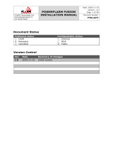
6 Functions
6.1 RS485 (LX90x0, LX80x0)
Function button (Fn) has customisable functionality, which can be set by the user
in Setup–>Hardware–>Remote menu.
Mode left /
Blue dot button
Function button
Mode right
Push to talk
Joystick /
Push=Enter/Select
Speed to fly button
Cancel / close

Rev #6 Version 1.11 May 2021
Page 12 of 15
6.2 CAN (S8x, S10x)
Speed to fly button

Rev #6 Version 1.11 May 2021
Page 13 of 15
7 Dimensions
7.1 Normal insert
7.2 Slanted insert
7.2.1 Mounting screws (DIN 916/ISO 4029 M 3 x 6)

Rev #6 Version 1.11 May 2021
Page 14 of 15
8 Revision history
Rev
Date
Comment
1
April 2018
Added chapter 1, 3, 6 and 7
2
May 2020
Added chapte7
3
January 2021
Style update
4
February 2021
Updated chapter 7
5
May 2021
Added chapters 5.2 and 5.4.2
Updated chapter 7
6
May 2021
Combined manuals for RS485 and CAN versions of Remote

Rev #6 Version 1.11 May 2021
Page 15 of 15
/