Page is loading ...

POWERFLARM FUSION
INSTALLATION MANUAL
Date: 2020-11-10
Version: 1.0
Page: 1 of 38
FLARM Technology Ltd
Hinterbergstrasse 15
CH-6330 Cham
Document Number:
FTD-077
Document Status
Published status
Confidentiality status
☐
Draft
☒ Released
☐
Canceled
☐
Internal
☐ NDA
☒
Public
Version Control
Ver.
Date
Summary of changes
1.0
2020-11-10
Initial version

POWERFLARM FUSION
INSTALLATION MANUAL
Date: 2020-11-10
Version: 1.0
Page: 2 of 38
FLARM Technology Ltd
Hinterbergstrasse 15
CH-6330 Cham
Document Number:
FTD-077
Table of contents
1 General Overview .............................................................................. 4
1.1 System Description .................................................................. 6
1.2 Definitions .............................................................................. 7
1.2.1 Abbreviations ............................................................ 7
1.2.2 Terminology.............................................................. 8
1.3 Displays ................................................................................. 8
1.4 Radio Communication and Antennas ........................................... 8
1.5 Additional Documents, Data, and Information ............................. 10
1.6 Document Revisions ................................................................ 10
2 Installation ...................................................................................... 11
2.1 General Requirements and Advice on Installation ......................... 11
2.1.1 Minor Change and Standard Change ............................ 12
2.2 Housing ................................................................................ 12
2.3 Displays ................................................................................ 13
2.4 Connections and Cabling .......................................................... 14
2.4.1 Overview ................................................................. 14
2.4.2 General Advice ......................................................... 15
2.4.3 Circuit Breaker ......................................................... 15
2.4.4 Power Supply ........................................................... 15
2.4.5 Display ................................................................... 16
2.4.6 RJ45 – Power and Data Connections ............................ 16
2.4.7 D-sub DE-9 – Power, Data, and Audio Connections ........ 17
2.4.8 Audio Out ................................................................ 18
2.4.9 FLARM and 1090 MHz Antenna Connectors ................... 19
2.4.10 GPS Antenna (SMC Connector) ................................... 20
2.5 Antennas ............................................................................... 20
2.5.1 External Antennas .................................................... 20
2.5.2 Internal Antennas ..................................................... 22
2.6 USB Connector ....................................................................... 23
2.7 Firmware Updates ................................................................... 24
2.8 Configuration ......................................................................... 24
2.9 Annual Maintenance ................................................................ 25

POWERFLARM FUSION
INSTALLATION MANUAL
Date: 2020-11-10
Version: 1.0
Page: 3 of 38
FLARM Technology Ltd
Hinterbergstrasse 15
CH-6330 Cham
Document Number:
FTD-077
2.10 Installation Verification ............................................................ 25
3 Technical Specification .................................................................... 26
4 Additional Information .................................................................... 27
4.1 Troubleshooting and Error Codes ............................................... 27
4.2 Warranty Information and Terms of Use ..................................... 27
4.3 Replacing PowerFLARM Core with PowerFLARM Fusion .................. 27
4.4 Replacing Classic FLARM with PowerFLARM Fusion ....................... 27
4.5 Conformity Declarations .......................................................... 28
4.6 Maximum Antenna Gain ........................................................... 29
4.7 Industry Canada Notice and Marking .......................................... 29
Appendix A – Mechanical Drawings ....................................................... 30
Appendix B – Acceptable Antennas and Cables ..................................... 31
Appendix C – FLARM Compatible Displays ............................................. 32
Appendix D – Installation Verification Checklist .................................... 34
Appendix E – End User License Agreement (EULA) ................................ 37

POWERFLARM FUSION
INSTALLATION MANUAL
Date: 2020-11-10
Version: 1.0
Page: 4 of 38
FLARM Technology Ltd
Hinterbergstrasse 15
CH-6330 Cham
Document Number:
FTD-077
1 General Overview
FLARM is the collision avoidance system and traffic awareness/electronic
conspicuity technology used by General Aviation, light aircraft, and UAVs. It has
been designed to support self-separation for both VFR and IFR in applicable
airspace classes. Aircraft with a FLARM system alert the pilots when on a collision
course with another aircraft. Similar to TCAS/TAS, visual and aural warnings
indicate that a collision is imminent, requiring the pilots to take action. However,
unlike TCAS, FLARM does not issue Resolution Advisories (RA), so pilots need to
select the appropriate course of action themselves.
FLARM works by calculating and broadcasting its own predicted future 3D flight
path to nearby aircraft. At the same time, it receives the future flight path from
surrounding aircraft. An intelligent motion prediction algorithm calculates a
collision risk for each aircraft based on an integrated risk model.
The system determines its position, altitude, and movement with a sensitive GNSS
receiver. Based on those and other parameters, a precise projected flight path can
be calculated. The flight path, together with additional information such as an
identification number, is encoded before being broadcast over an encrypted radio
channel twice per second. Flight models are available for most aircraft types,
including piston-engine airplanes, jets, helicopters, gliders, hang gliders,
paragliders, UAVs, etc.
PowerFLARM Fusion also incorporates an ADS-B and transponder (SSR) Mode-S
receiver. This enables aircraft that are not yet equipped with FLARM to also be
detected and included in the collision prediction algorithm. However, these aircraft
will not be able to detect FLARM-equipped aircraft, so a reciprocal FLARM-
installation is recommended for all aircraft.
FLARM was invented in 2004 following an increasing number of mid-air collisions.
Research and accident investigations had shown that the see-and-avoid principle
was insufficient to reliably detect approaching aircraft in time. It initially spread in
the domain of non-powered aircraft but was soon followed by rapid expansion in
powered airplanes and helicopters. Over 50,000 manned aircraft and many more
UAVs already have a FLARM-system installed. In Europe, more than 50% of all
General Aviation aircraft have FLARM (including nearly 100% of gliders). The
technology has additionally spread to other parts of the world and is today also
used most prominently in North and South America, Australia, New Zealand, South
Africa, Israel, and some Asian countries.
In addition to annunciating collision warnings, many FLARM systems can also show
nearby aircraft on a radar-like screen (CDTI). Similar to the use of weather radar

POWERFLARM FUSION
INSTALLATION MANUAL
Date: 2020-11-10
Version: 1.0
Page: 5 of 38
FLARM Technology Ltd
Hinterbergstrasse 15
CH-6330 Cham
Document Number:
FTD-077
to avoid thunderstorms, this can sometimes be helpful for short to medium term
strategic planning in high traffic density situations.
FLARM can also warn about fixed obstacles like masts and power lines. Obstacle
collision warnings are based on an optionally installed database, which needs to
be kept up to date.
FLARM systems are available from many different manufacturers under different
product names. A system normally consists of a remotely installed FLARM device,
a panel-mounted FLARM Compatible display, one or two externally mounted
FLARM antennas, and internally mounted GNSS and ADS-B/SSR antennas. There
are also portable FLARM devices available (usually with an integrated display), as
well as FLARM systems integrated into other avionics (e.g. EFIS-systems).
FLARM is approved by EASA and others for installation in certified aircraft and is
recommended by many aviation authorities and organizations. The installation is
normally a minor change and can be done by any competent maintenance
organization. Several General Aviation airports have started requiring FLARM for
all aircraft. FLARM is also mandatory in France for gliders and a similar requirement
for light powered aircraft is under investigation.

POWERFLARM FUSION
INSTALLATION MANUAL
Date: 2020-11-10
Version: 1.0
Page: 6 of 38
FLARM Technology Ltd
Hinterbergstrasse 15
CH-6330 Cham
Document Number:
FTD-077
1.1 System Description
PowerFLARM Fusion is a modern FLARM device for installation in General Aviation
aircraft. It is based on the latest PowerFLARM technology and features a novel web
app called FLARM Hub. PowerFLARM Fusion has been designed for worldwide use
and connects to a range of displays, including tablet apps via Wi-Fi or Bluetooth.
A FLARM system consists of several parts. PowerFLARM Fusion, or Fusion for
short, contains the collision computer, radio circuitry, and peripheral
communication subsystems. It is powered from the aircraft electrical system and
connects to the following equipment and parts:
One or two FLARM antennas. Installed antennas can be either external or
internal. The choice depends on the antenna function and aircraft type.
External antennas are mounted outside the aircraft fuselage (normally on
top and below the aircraft). Internal antennas are mounted inside the aircraft
fuselage (e.g. in the cockpit or in gliders also in the vertical stabilizer). The
use of two antennas (antenna diversity) allows for an improved coverage.
A 1090 ADS-B/SSR antenna (optional) for receiving Mode-S and ADS-B
signals.
A GPS antenna used by Fusion to determine its trajectory.

POWERFLARM FUSION
INSTALLATION MANUAL
Date: 2020-11-10
Version: 1.0
Page: 7 of 38
FLARM Technology Ltd
Hinterbergstrasse 15
CH-6330 Cham
Document Number:
FTD-077
A panel mount USB socket with extension cord for a USB flash drive.
At least one FLARM Compatible display. These displays have been certified
or validated to have implemented all essential functions.
A number of complementary displays or accessories, parsing the FLARM data
stream.
An audio panel for feeding aural warnings into the aircraft’s audio system
(optional).
An Electronic Flight Bag (EFB) or navigation app running on a mobile device
(tablet or phone), connected through Wi-Fi or Bluetooth.
A web browser running FLARM Hub on a computer or mobile device.
1.2 Definitions
1.2.1 Abbreviations
Abbreviation
Meaning/Explanation
ADS-B
Automatic Dependent Surveillance — Broadcast
AFMS
Aircraft Flight Manual Supplement
AML
Approved Model List
AMP
Aircraft Maintenance Program
CAA
Civil Aviation Authority
CDTI
Cockpit Display of Traffic Information
CRS
Certificate of Release to Service
EFIS
Electronic Flight Instrument System
(E)TSO
(European) Technical Standard Order
FAQ
Frequently Asked Questions and answers
GND
Ground (Earth)
GNSS
Global Navigation Satellite System
GPS
Global Positioning System (NAVSTAR)
ICA
Instructions for Continued Airworthiness
ICD
Interface Control Document
IFR
Instrument Flight Rules
ISM
The ISM radio bands (FLARM uses ≈ 915 MHz)
MCA
(EASA) Minor Change Approval
RF
Radio Frequency/Radio
SRD860
The SRD860 radio band (FLARM uses ≈ 868 MHz)
SSR
Secondary Surveillance Radar
STC
Supplemental Type Certificate
TAS
Traffic Advisory System
TCAS
Traffic alert and Collision Avoidance System
UAV
Unmanned Aerial Vehicle
VFR
Visual Flight Rules
XPDR
Transponder

POWERFLARM FUSION
INSTALLATION MANUAL
Date: 2020-11-10
Version: 1.0
Page: 8 of 38
FLARM Technology Ltd
Hinterbergstrasse 15
CH-6330 Cham
Document Number:
FTD-077
1.2.2 Terminology
The words shall and must are used to indicate a mandatory requirement.
The word should is used to indicate a recommendation, meaning that there may
exist valid reasons in particular circumstances not to follow a specific item, but the
full implications must be understood and carefully weighed before choosing a
different course.
The word may is used to indicate that an item is truly optional.
1.3 Displays
PowerFLARM Fusion must be connected to a FLARM display. Displays originate from
third party manufacturers implementing the FLARM ICD protocol, an extension of
NMEA 0183. To ensure that collision warnings and traffic information work correctly
and that critical status and error conditions are correctly annunciated to the pilots,
Fusion should be connected to at least one FLARM Compatible display.
A list of displays certified as FLARM Compatible, as well as alternative means of
compliance, can be found in Appendix C. Displays certified as FLARM Compatible
can also be found in the Product Selector under the category “Primary Displays”:
https://flarm.com/products/powerflarm/product-selector/
Fusion also supports connections to supplementary displays and navigation
systems over Wi-Fi and Bluetooth.
1.4 Radio Communication and Antennas
The FLARM system uses a radio communication frequency in the SRD860 band
(≈ 868 MHz) or an ISM band (≈ 915 MHz) in different parts of the world.
PowerFLARM Fusion will automatically select the applicable frequency based on the
GNSS position.
The following frequencies are used within the specified areas.
Area
Frequency
Africa
868.2 – 868.4 MHz
Australia
917.0 – 926.6 MHz
Europe
868.2 – 868.4 MHz
Israel
916.2 MHz
New Zealand
869.2 MHz
North America
902.2 – 927.8 MHz
South America
917.0 – 926.2 MHz

POWERFLARM FUSION
INSTALLATION MANUAL
Date: 2020-11-10
Version: 1.0
Page: 9 of 38
FLARM Technology Ltd
Hinterbergstrasse 15
CH-6330 Cham
Document Number:
FTD-077
The antennas should be designed for the frequency band applicable in the
geographic area where the aircraft is being operated. Internal antennas, including
the antennas that are shipped with Fusion, are normally designed for only one of
the frequency bands. The external AV-75 antenna is designed for worldwide use.
Only antennas supplied by FLARM Technology should be used. In addition, other
antennas as specified in Appendix B may be used as well. Inappropriate antennas,
especially antennas without complete insulation, can damage devices and should
not be used.
Note: Fusion will not detect inappropriate antennas, including antennas for the
wrong frequency band.
PowerFLARM Fusion can use two antennas concurrently for better coverage
(antenna diversity). Normally, one antenna is placed on top of the aircraft and one
below. In especially fiberglass gliders, they can also be placed inside the aircraft
fuselage in a way that ensures 360° coverage. Antenna diversity is recommended
for all aircraft and is strongly recommended for aircraft fuselages containing a lot
of metal or carbon fiber.
Note: Communication between FLARM devices employs a proprietary, encrypted,
and copyright protected protocol. The design is patent protected. Any
unlicensed use, copying, distribution, conversion, replication, access,
interception, de-compiling, reverse engineering, or further transmission of
knowledge so acquired relating to the system components or
software/firmware, in whole or in part, is forbidden and will result in legal
enforcement action.

POWERFLARM FUSION
INSTALLATION MANUAL
Date: 2020-11-10
Version: 1.0
Page: 10 of 38
FLARM Technology Ltd
Hinterbergstrasse 15
CH-6330 Cham
Document Number:
FTD-077
1.5 Additional Documents, Data, and Information
The PowerFLARM Fusion User and Maintenance Manual (FTD-078) is an integral
part of the installation and maintenance documentation and must be used for the
installation where referenced. The User and Maintenance Manual also serves as
the Instructions for Continued Airworthiness (ICA), unless replaced by an ICA as
part of the Minor Change Approval or STC in applicable parts. The User and
Maintenance Manual, together with additional documents for installation,
maintenance, operation, and support can be found under the following link:
https://flarm.com/support/manuals-documents/
The EASA Minor Change Approval (MCA) and documents for a Standard Change
installation can be acquired under the following link:
https://flarm.com/product-category/approvals/
Obstacle databases can be acquired under the following link:
https://flarm.com/product-category/obstacle-databases/
For questions, first consult the FAQ:
https://support.flarm.com/hc/en-us
For questions not answered in the FAQ, contact FLARM Technology:
1.6 Document Revisions
This document will occasionally be updated. The latest version can be found under
the link to additional documents above. Always make sure that you are using the
latest document. Updates will be communicated to official FLARM dealers, in the
FLARM blog, and the official FLARM newsletter. Sign up to the newsletter from the
FLARM website to ensure that important communication is not missed:
https://flarm.com/blog/

POWERFLARM FUSION
INSTALLATION MANUAL
Date: 2020-11-10
Version: 1.0
Page: 11 of 38
FLARM Technology Ltd
Hinterbergstrasse 15
CH-6330 Cham
Document Number:
FTD-077
2 Installation
2.1 General Requirements and Advice on Installation
FLARM is not required by any Certification Specification. Thus, there is no (E)TSO
for FLARM, nor is one required. The installation is normally a minor change and
must adhere to the Certification Specification applicable to the aircraft in which it
is installed. The Certification Compliance List is an integral part of the minor change
approval process (see Section 2.1.1). The installation may only be performed by
competent personnel. Following installation in certified aircraft, a Certificate of
Release to Service (CRS) must be issued by Part-66 certifying staff, or the national
equivalent. The installation cannot be done as part of pilot-owner maintenance.
Unauthorized installations will void any warranty.
For certified aircraft, an MCA (Minor Change Approval) or
Standard Change installation with appurtenant documents is
required. See Section 2.1.1 for details.
The installation must not obstruct the pilots in their operation of the aircraft
(including emergencies); in particular, it must not obstruct outside view or
emergency egress.
Only one single FLARM device may be installed and active in the aircraft.
PowerFLARM Fusion should be installed at least 30 cm from the magnetic compass.
As part of the installation, Fusion must be updated to the latest firmware version
and the device must be configured correctly. See Sections 2.7 and 2.8 for details.
After installation, an inspection must be made to ensure that the installation does
not interfere with any mechanical, electrical, electronic (radio), or magnetic (e.g.
compass) system. The installation shall be recorded in the aircraft maintenance
documents. The annual maintenance (see Section 2.9) must be added to the
Aircraft Maintenance Program (AMP); see MCA documents for details. An approved
AFM Supplement must be carried on board the aircraft. The EASA approved AFM
Supplement is available as part of the MCA.
After the first few flight hours, the installation should be verified by using the range
analyzer. See Section 2.10 for details and the Installation Verification Checklist in
Appendix D.
For additional guidance on FLARM installations (especially for rotorcraft), see EASA
Certification Memorandum CM-AS-010.

POWERFLARM FUSION
INSTALLATION MANUAL
Date: 2020-11-10
Version: 1.0
Page: 12 of 38
FLARM Technology Ltd
Hinterbergstrasse 15
CH-6330 Cham
Document Number:
FTD-077
2.1.1 Minor Change and Standard Change
For certified aircraft, an MCA (Minor Change Approval) or Standard Change
installation with appurtenant documents is required. The MCA covering many
aircraft types, as well as required Standard Change documentation, can be
acquired under the following link:
https://flarm.com/product-category/approvals/
The documents are also required for a Standard Change installation. This includes
the AFM Supplement, Installation instructions, as well as Instructions for continued
airworthiness. These documents can also be used for an individual Minor Change
for other aircraft types.
Note: A Standard Change installation is normally more limiting than an MCA (e.g.
limited to day VFR).
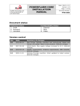
2.2 Housing
Mount PowerFLARM Fusion to a suitable mounting location. The orientation of the
device is discretionary. Do not mount the device on the “hot” side (engine side) of
the firewall. Common installation locations are behind the instrument panel or in
the E&E compartment in larger aircraft. To ensure that the Wi-Fi and Bluetooth
connection works for the pilots (if it is intended to be used), install Fusion in a
location that does not hinder the propagation of the Wi-Fi and Bluetooth signal to
the pilot compartment. The Wi-Fi and Bluetooth antenna is located behind the
sticker indicated below:
Wi-Fi and Bluetooth antenna location
The metallic housing is not waterproof, and ingress of solid particles and liquids
must be avoided. Should the device get moist, it must be completely dried prior
to further use. If the device becomes wet, it may be permanently damaged and

POWERFLARM FUSION
INSTALLATION MANUAL
Date: 2020-11-10
Version: 1.0
Page: 13 of 38
FLARM Technology Ltd
Hinterbergstrasse 15
CH-6330 Cham
Document Number:
FTD-077
rendered unusable. Should the device be suddenly cooled, this may result in the
formation of condensation.
Mechanical drawings of the device are available in Appendix A.
2.3 Displays
PowerFLARM Fusion should be connected to a FLARM Compatible display as a
primary means of collision avoidance. The display should be installed in the
primary field of view of the pilots. In aircraft with tandem seating, each pilot should
have a display in its primary field of view. Install the latest display firmware, if
applicable. It can be acquired from the display manufacturer. See the Installation
Instructions for the relevant display for specific instructions.
Many “FLARM displays” on the market have not been certified
as FLARM Compatible
. Certified displays carry the FLARM
Compatible logo. Lack of certification may lead to the absence
of collision warnings and error/status codes
, including
firmware expiration.
A list of displays certified as FLARM Compatible, as well as alternative means of
compliance, can be found in Appendix C. Displays certified as FLARM Compatible
can also be found in the Product Selector under the category “Primary Displays”:
https://flarm.com/products/powerflarm/product-selector/
In addition to the connection to a FLARM Compatible display, Fusion can be
connected to a range of other displays, EFIS systems, and tablet applications. This
can be accomplished either as a cable connection or using Wi-Fi or Bluetooth. See
the User and Maintenance Manual for details.

POWERFLARM FUSION
INSTALLATION MANUAL
Date: 2020-11-10
Version: 1.0
Page: 14 of 38
FLARM Technology Ltd
Hinterbergstrasse 15
CH-6330 Cham
Document Number:
FTD-077
2.4 Connections and Cabling
2.4.1 Overview
PowerFLARM Fusion has the following connectors:
USB 2.0: Accepts USB flash drive for flight log readout, device update1, and
configuration.
FLARM antennas A and B: When using a single antenna, connect to FLARM
A. The internal FLARM antennas supplied with the device have a RED
marking.
1 The FLARM Hub Firmware cannot be updated using USB.

POWERFLARM FUSION
INSTALLATION MANUAL
Date: 2020-11-10
Version: 1.0
Page: 15 of 38
FLARM Technology Ltd
Hinterbergstrasse 15
CH-6330 Cham
Document Number:
FTD-077
1090 MHz: For receiving SSR transponder and ADS-B 1090ES signals. The
internal antenna supplied with the device has a BLUE marking. This antenna
is optional; however, without it, no traffic will be received on 1090 MHz.
GPS antenna: Must be connected for operation.
RJ45 (Data Port #1) and D-sub DE-9 (Data Port #2): For connecting up to
two independent FLARM Compatible displays and power. Power must only be
supplied on one of the connectors.
2.4.2 General Advice
Before connecting the cables for the first time, check all connectors with a
continuity tester. Pay special attention to the power supply pins.
Connecting power to an incorrect pin will damage the circuit
board, make the device unusable, and void any warranty.
Cables must not be cracked, excessively bent, or installed under tension. Adequate
space must be left for the cable connectors.
2.4.3 Circuit Breaker
Connect Fusion (and the FLARM Compatible display) via a combined 3 A circuit
breaker/switch or separate circuit breaker and switch. The Fusion circuit breaker
must be separate from other circuit breakers of essential systems.
In flight, the pilots must be able to isolate FLARM from the aircraft's electrical
system without interrupting the power supply to other essential avionics.
2.4.4 Power Supply
Supply voltage: 12 to 32 V DC. Typical current drain is 180 mA @ 12 V, less for
higher voltages, more if external components are supplied by Fusion.
Connect power either through the D-sub (pin 7) or the RJ45 connector (pin 7 and
8). Do not provide power to both.

POWERFLARM FUSION
INSTALLATION MANUAL
Date: 2020-11-10
Version: 1.0
Page: 16 of 38
FLARM Technology Ltd
Hinterbergstrasse 15
CH-6330 Cham
Document Number:
FTD-077
2.4.5 Display
See Section 2.3 and Appendix C for display requirements.
Use only high-quality shielded cables for the display connections. Up to 5 m cable
length is normally acceptable.
If the display requires 3 V DC operating voltage, the respective pin on the RJ45 or
D-sub connector may be used. Otherwise, the display should be connected to
power according to Section 2.4.3.
2.4.6 RJ45 – Power and Data Connections
Connecting power to an incorrect
pin will burn the circuit
board, make the device unusable, and void any warranty.
The 8-pin RJ45-socket (8P8C) is in accordance with IGC GNSS FR specifications,
except for pin 6.
1: GND
2: GND
3: RX, Fusion receives (RS-232)
4: TX, Fusion sends (RS-232)
5: GND
6: Fusion supplies +3 V DC for display
7: +12 to +32 V DC power supply
8: +12 to +32 V DC power supply
Do not connect more than one external application to the RJ45 port.
Maximum current on pin 6: 200 mA @ 3 V DC.
Note: Pin 7 of the D-sub connector and Pins 7 and 8 of the RJ45 connector are
internally connected. So are the GND pins 5 (D-sub) and 1, 2, 5 (RJ45).

POWERFLARM FUSION
INSTALLATION MANUAL
Date: 2020-11-10
Version: 1.0
Page: 17 of 38
FLARM Technology Ltd
Hinterbergstrasse 15
CH-6330 Cham
Document Number:
FTD-077
2.4.7 D-sub DE-9 – Power, Data, and Audio Connections
Connecting power to an incorrect pin will burn the circuit
boards, make the device unusable and void any warranty.
The 9-pin DE-9 connector is shown below. On the left side, the female socket on
Fusion is shown. On the right side, the male plug (on the cable) is shown.
Socket (device) Plug (cable)
1: Audio OUT (referenced to GND)
2: TX, Fusion sends (RS-232)
3: RX, Fusion receives (RS-232)
4: Do not connect
5: GND
6: Do not connect
7: +12 to +32 V DC power supply
8: Fusion supplies +5 V DC
9: Fusion supplies +3 V DC for display
Do not connect more than one external application to the RS-232 port.
Maximum current on pin 9: 200 mA @ 3 V DC; independent of pin 6 of the RJ45
connector.
Maximum current on pin 8: 700 mA @ 5 V DC; shared with the USB port.
Note: If using 5 V DC (pin 8) and USB at the same time, the shared maximum
700 mA applies.

POWERFLARM FUSION
INSTALLATION MANUAL
Date: 2020-11-10
Version: 1.0
Page: 18 of 38
FLARM Technology Ltd
Hinterbergstrasse 15
CH-6330 Cham
Document Number:
FTD-077
D-sub cables shipped with Fusion are color coded according to the following table.
These D-Sub cables are marked with “Art.-Nr 1420531”. DO NOT use the color
coding if the cable is not marked accordingly. Use a continuity tester instead
to determine the assignment.
Grey
Pin 1: Audio Out
Yellow
Pin 2: TX, Fusion sends (RS-232)
Green
Pin 3: RX, Fusion receives (RS-232)
Brown
Pin 4: Do not connect
White
Pin 5: GND
Red
Pin 7: +12 to +32 V DC power supply
Pink
Pin 8: Fusion supplies +5 V DC
Blue
Pin 9: Fusion supplies +3 V DC for display
Note: There is no wire for Pin 6!
Note: Pin 7 of the D-sub connector and Pins 7 and 8 of the RJ45 connector are
internally connected. So are the GND pins 5 (D-sub) and 1, 2, 5 (RJ45).
2.4.8 Audio Out
PowerFLARM Fusion emits an intermittent 1 kHz waveform on Audio Out (Pin 1 on
the D-sub connector) whenever a collision warning is issued. The frequency of the
beep depends on the time to collision. In addition, a test beep is emitted during
power-up if Audio out has been activated in the configuration.
Many FLARM Compatible displays have their own audio warnings. Audio Out only
needs to be connected when the audio warning of the connected FLARM
Compatible display is absent or not loud enough in loud cockpit environments.
Note: Audio Out is configured OFF by default. If connected, it must be enabled
during configuration.

POWERFLARM FUSION
INSTALLATION MANUAL
Date: 2020-11-10
Version: 1.0
Page: 19 of 38
FLARM Technology Ltd
Hinterbergstrasse 15
CH-6330 Cham
Document Number:
FTD-077
Electrical characteristics:
AC signal, 1.7 V peak-to-peak @ 1 kΩ
Referenced to GND (pin 5), no DC bias
Output impedance: 47 Ω
Output current (max.): 35 mA
Connect Audio Out to the audio panel or other amplifier with input impedance
between 200 Ω and 10 kΩ. The audio panel or amplifier should allow volume
adjustment.
Note: Do not connect a headset or speaker directly to Audio Out.
2.4.9 FLARM and 1090 MHz Antenna Connectors
FLARM A and B ports are reverse polarity female SMA connectors (RP-SMA) with a
pin as center conductor. The 1090 port is a standard female SMA connector.
Ensure that the antenna cable connectors are properly and fully screwed into the
device. Use only little force when inserting and tightening (max 1 Nm).
Note: If replacing a PowerFLARM Core E-version with PowerFLARM Fusion, the
antenna connectors differ. See Section 4.3 for details.
Never try to swap the FLARM and 1090 antennas or use
antennas with incorrect polarity (SMA vs. RP-SMA). Doing so
may cause permanent mechanical damage to the device.

POWERFLARM FUSION
INSTALLATION MANUAL
Date: 2020-11-10
Version: 1.0
Page: 20 of 38
FLARM Technology Ltd
Hinterbergstrasse 15
CH-6330 Cham
Document Number:
FTD-077
2.4.10 GPS Antenna (SMC Connector)
PowerFLARM Fusion contains a 72 channel GNSS receiver, connecting to an
external antenna. Ensure that the antenna cable is properly and fully screwed into
the device. Fusion will not work without good GPS reception.
2.5 Antennas
The minimum number of antennas required for installation is one FLARM antenna
and one GPS antenna. In addition, a second FLARM antenna should be installed
for antenna diversity. The system can also optionally receive SSR transponder
Mode-S and ADS-B 1090ES traffic on 1090 MHz using a separate 1090 antenna
(recommended).
All antennas may be installed either externally (on the aircraft fuselage) or
internally (inside the aircraft fuselage). External antennas are normally mounted
on top and below the aircraft. Internal antennas are normally mounted on the
glareshield or otherwise in the cockpit next to one of the side windows. In
fiberglass gliders, internal antennas can sometimes also be mounted inside the
vertical stabilizer. External antennas for FLARM A and FLARM B are strongly
recommended for all aircraft for the best performance (range). For GPS and 1090,
internal antennas are usually suitable in most light aircraft.
The antennas supplied with the device may only be mounted internally. Additional
approved and acceptable antennas are listed in Appendix B.
Note: Except for the AV-75 antenna, FLARM antennas are made for either the
SRD860 or ISM band, used in different parts of the world (see Section 1.4
for details). The antennas shipped with the device are for the band
applicable in the country where the device was sold. Ensure that the correct
antenna type for the intended area of operation is installed.
2.5.1 External Antennas
External FLARM antennas should be installed in most aircraft. An external 1090
antenna is recommended for aircraft with MTOM above 2,000 kg, as well as lighter
aircraft where installation of the internal antenna is not feasible. For external
antennas, follow the requirements below.
Poor RF cables attenuate the radio signal and can lead to severely degraded
range. Use only low-attenuation RF cables, especially if the cable is longer
than 1.5 m. The total attenuation per antenna cable should be less than 3
dB.
Minimize cable lengths to ensure maximum signal strength.
/