Page is loading ...


Logos Digital Imaging System 1
User Manual v 4.1.5
INTRODUCTION
Logos Digital Imaging System by LOGOS
IMAGING
Congratulations on your purchase of the
Logos Digital Imaging System. The Logos
Digital Imaging System is a revolutionary
product designed to replace traditional x-ray
film and film processors.
TECHNICAL SUPPORT
For technical support, call Logos Imaging
directly at (866)939-4044
SUPPLIES AND REPLACEMENT
PARTS
To order supplies or replacement parts for
your Logos Digital Imaging System, call
your Logos Imaging equipment dealer. If
your dealer is unable to assist you, call
Logos Imaging at (866)939-4044.

Logos Digital Imaging System 2
User Manual v 4.1.5
TABLE OF CONTENTS
Section 1: Use .............................................................................................................................. 2
Section 2: Safety Requirements ................................................................................................. 3
2.1. IMPORTANT INFORMATION ................................................................................................. 3
2.2. WARNINGS AND CAUTION STATEMENTS ........................................................................ 3
Section 3: Pre-Installation Information and Recommendations ............................................ 5
3.1. PURPOSE OF THE MANUAL .................................................................................................. 5
3.2. ABBREVIATIONS AND EXPLANATION OF SYMBOLS .................................................... 5
3.3. PHYSICAL DESCRIPTION ....................................................................................................... 6
3.4. COMPUTER REQUIREMENTS ................................................................................................ 9
3.5. ELECTRICAL REQUIREMENTS ............................................................................................. 9
3.6. COMPLIANCE TO STANDARDS ............................................................................................ 9
Section 4: Installation ............................................................................................................... 10
4.1. SITE SELECTION .................................................................................................................... 10
4.2. UNPACKING THE UNIT ........................................................................................................ 11
4.3. LOADING THE LOGOS SCANNER DRIVER SOFTWARE ................................................ 12
4.4. HARDWARE SETUP AND CONNECTIONS ........................................................................ 12
Section 5: System Operating Instructions .............................................................................. 13
5.1. PREPARING YOUR CURRENT X-RAY EQUIPMENT ....................................................... 13
5.2. ERASE THE IMAGING PLATE .............................................................................................. 13
5.3. TAKING AN X-RAY ............................................................................................................... 14
5.4. SCANNING THE IMAGING PLATE ...................................................................................... 15
5.5. TURNING OFF THE LOGOS SCANNER SYSTEM ............................................................. 16
Section 6: Software Operating Instructions ........................................................................... 17
Section 7: Maintenance Procedures ........................................................................................ 18
7.1. CLEANING THE SYSTEM ..................................................................................................... 18
7.2. OPERATOR MAINTENANCE ................................................................................................ 19
7.3. TROUBLESHOOTING ............................................................................................................ 20
7.4. DISPOSAL OF WASTE MATERIALS AND INOPERARTIVE PARTS .............................. 22
Section 8: Storage and Shipment ............................................................................................ 23
8.1. STORAGE ................................................................................................................................. 23
8.2. SHIPMENT ............................................................................................................................... 23
Section 9: Technical Specifications ......................................................................................... 24
9.1. SPECIFICATIONS ................................................................................................................... 24
Section 10: Warranty Statement ........................................................................................... 25
Appendix A: Storage Phosphor Technology ………………………………………………....... 26
Appendix B: Lighting Conditions for Handling or Erasing Imaging Plates ……………..... 27
Appendix C: Optional Printer ………..........................................................................………. 29
Appendix D: Warranty Registration ..……………………………………………………........…. 31

Logos Digital Imaging System 3
User Manual v 4.1.5
SECTION 1: USE
The Logos Digital Imaging System is
intended for use as a general radiography
system using x-ray recording media
(phosphor imaging plates) for radiographic
analysis providing interactive CRT retrieval,
viewing and processing of stored computed
radiographic images.
The system includes reusable
photostimulatable phosphor imaging plates,
a laser diode scanner device and optical
reader components, communications
electronics and software, a notebook
computer, carrying case, and various
peripheral accessories.
The Logos Scanner is not intended for medical imaging of humans.

Logos Digital Imaging System 4
User Manual v 4.1.5
SECTION 2: SAFETY REQUIREMENTS
2.1. IMPORTANT INFORMATION
It is important that all personnel who will
operate the Logos Digital Imaging System
read and understand this manual before
operating the device. All personnel should
follow all warnings and precautions as
outlined in Section 2.2, for their safety and
the safety of others around them.
2.2. WARNINGS AND CAUTION STATEMENTS
In this manual, the following definitions
apply for all WARNINGS and CAUTION
statements:
Warnings: Any operation, procedure or
practice, which, if not strictly observed, may
result in injury or long-term health hazards.
Cautions: Any operation, procedure or
practice, which, if not strictly observed, may
result in destruction of equipment or loss of
effectiveness.
WARNINGS
The Logos Digital Imaging System should
be used only by trained professional.
Do not open the device to service it.
None of the internal parts of the scanner are
user serviceable. The only user serviceable
parts of the system are outlined in Section
7.2. If there is a service problem, call Logos
Imaging at (866)939-4044.
Use only grounded electrical connections.
Connect the Logos scanner to a grounded
electrical outlet between 100-240 volts AC.
Imaging plates are toxic!
The blue colored substance in the imaging
plate is toxic. If part/all of an imaging plate
is swallowed, contact a physician
immediately. The physician must remove
the imaging plate. Do not use cracked, bent
or chipped imaging plates.
Never chew or swallow the imaging plates
If the imaging plate is bitten or chewed and
damages the protective barrier envelope,
rinse the mouth with a large amount of
water. If any of the blue surface of the plate
is swallowed, contact a doctor immediately.
The Logos scanner is a Class 1 laser
device per EN60825-1/A2:2001 U.S. 21
CFR Chapter I Subchapter J.
Caution: Use of controls or adjustments or
performance of procedures other than those
specified herein may result in hazardous
radiation exposure. A fail-safe switch in the
carousel well and cover keeps the laser
inactive as long as the cover is open. Only a
trained technician from Logos Imaging
should remove the cover from the scanner.
Direct eye contact with the output beam
from the laser may cause serious damage
and possible blindness.
Use only fuses with the required current
rating and of the specified type.
Make sure that only fuses with the required
current rating and of the specified type are
used for replacement. The use of incorrect
or makeshift fuses or the short-circuiting of
fuses holders creates a shock hazard for the
operator and may damage the device.

Logos Digital Imaging System 5
User Manual v 4.1.5
CAUTION STATEMENTS
Completely erase the imaging plates.
Before reusing an imaging plate, lay it white
surface up facing a bright light source for
two (2) minutes as described in Section 5.2.
Mount the imaging plates under low light
conditions.
Mount the imaging plates to the carousel
under low light conditions as described in
Section 5.4. Exposure to direct sunlight or
direct indoor lighting will erase the
information stored on the imaging plate.
Do not place scanner on or next to a
radiator or water source.
Excessive heat or small amounts of water
may damage the scanner’s electrical
components.
Do not leave unscanned, exposed imaging
plates in light.
Leaving unscanned, exposed imaging plates
in light will cause loss of image quality.
Do not scratch the imaging plates
When handling the imaging plate, do not
touch the active side (white) with fingernails
or any sharp object that might scratch the
surface. Do not lay unprotected imaging
plates face down.

Logos Digital Imaging System 6
User Manual v 4.1.5
SECTION 3: PRE-INSTALLATION INFORMATION AND
RECOMMENDATIONS
3.1. PURPOSE OF THE MANUAL
The instructions contained in this manual
should be carefully followed for safe,
trouble-free and effective equipment use.
This manual provides the essential
information necessary for the installation,
operation and routine care of the Logos
Digital Imaging System. This manual is not
to be used as a replacement for training in
radiography.
3.2. ABBREVIATIONS AND EXPLANATION OF SYMBOLS
AC alternative current
DC direct current
Hz Hertz; cycles per second
MHz Millions of hertz
LED light emitting diode
mm millimeter
cm centimeter
kVp peak voltage in thousands of
volts
IP imaging plates
CD-ROM compact disc, read-only
CCD charge-coupled device
TIFF tagged image file format
BMP bit-mapped
JFIF joint photographic image
format
JPEG joint photographic expert
group
LP/mm line pairs per mm
D.P.I. dots per inch
CPU central processing unit (your
computer)
in inch
IEC International Electrotechnical
Commission
| power on
O power off
green indicator, ready
yellow indicator, scanning
red indicator, error in scanning
high voltage
laser radiation
RAM random access memory
MB mega bytes
GB giga bytes
USB Universal Serial Bus
The CE symbol ensures that
the product herein specified
meets the applicable provisions
of the European Council
Directives.

Logos Digital Imaging System 7
User Manual v 4.1.5
3.3. PHYSICAL DESCRIPTION
The Logos Digital Imaging Systems consist of the following components:
Quantity Description
1 T100 scanner
1 Carousel, 8 x 10 in and/or 8 x 17 in, depending on
configuration
2 Imaging Plates, 8 x 10 in and/or 8 x 17 in, depending on
configuration
2 8x10 in image plate holders
2 8x17 in image plate holders
1 Logos Imaging software package
Includes PDF Operator’s Manual, PDF Software Manual,
and installation videos
1 USB cable, 6ft
1 Power Cord
Customer Supplied Components
Bottle of anhydrous isopropyl alcohol for cleaning imaging plates
Computer system as described in Section 3.4.
Optional Equipment from Logos Imaging
Imaging plate, 8 x 17
Imaging plate, 8 x 10
Image plate frames for connecting 8x17 image plates
Light box for erasing and storing imaging plates
Carrying Case

Logos Digital Imaging System 8
User Manual v 4.1.5
LOGOS IMAGING LASER SCANNER
Figure 3-1 Scanner Front View
c Carousel well and lid. The carousel, with imaging plates
attached, is inserted into the carousel well for scanning. The
carousel lid must be in the closed position prior to scanning. The
scanner will not operate with the lid open.
d LED indicator lights with graphic symbols.
The lights show the current status of the system.
Green — Ready to scan
Yellow — Scanning
Red — Error
Figure 3-2 Scanner REAR View
c Logos Scanner power entry module with switch and fuses
d USB connectors. A USB cable (provided) connects the Logos
Scanner to the CPU’s USB port.
e Power cord socket. The power cord (provided) will be
connected from this point to a grounded main outlet.
f Scanner label
f
1XXX
DECEMBER 2002

Logos Digital Imaging System 9
User Manual v 4.1.5
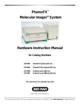
Figure 3-4 8 x 17 in. and 8 x 10 in. IMAGING PLATES
8 x 17 in 8 x 10
c Plastic mounting strips used to hold
imaging plate onto the carousel
d Active imaging area, white color
Figure 3-5 CAROUSELS
8 x 10 8 x 17
c Top of the carousel
d Imaging plate retaining device
Front (White)
Rear (Black)

Logos Digital Imaging System 10
User Manual v 4.1.5
3.4. COMPUTER REQUIREMENTS*
Minimum Computer Requirements Recommended
CPU Speed 1.0 GHz or higher
Operating system Windows XP Professional operating system
RAM 512 MB
Hard Drive 40 GB
CD ROM Drive 4X 24X
USB port USB 2.0 Required
Display 24-bit display (minimum 800x600 resolution)
Backup Device Highly recommended
Printer Recommended (see appendix C)
*See also the Imaging Software computer requirements.
3.5. ELECTRICAL REQUIREMENTS
Voltage 100-240 V AC 50/60 Hz power supply auto-senses the input voltage.
Power 100 watts maximum
Power Cord Standard line cord provided
3.6. COMPLIANCE TO STANDARDS
The Logos Digital Imaging System conforms to the following standards:
EN61000-4-2: Electrostatic discharge
EN61000-4-3: Radiated susceptibility
EN61000-4-4: Electrical fast transient and
burst
EN61000-4-5: Surge, AC 1 kV differential,
2 kV common
EN61000-4-6: Conducted disturbances, 9
kHz to 30 kHz. 3 VRMS
EN61000-4-8: Magnetic fields
EN61000-4-11: Voltage dips, interruptions,
and voltage variation
Part 15 of the FCC Rules
DHHS/CDRH: Radiation Performance
Standard, 21 CFR, Chapter I, Subchapter J
EN61010-1
EN60825-1
EN50082-1 / EN55011
CAN/CSA-C22.2 No. 1010.1-92
UL 3101-1

Logos Digital Imaging System 11
User Manual v 4.1.5
SECTION 4: INSTALLATION
4.1. SITE SELECTION
The Logos Scanner can be located almost
anywhere the operating conditions are met.
The site you pick should have:
] Subdued lighting conditions. You should
have the ability to turn down/off the
lights and block sunlight with blinds.
The area to be used for mounting
imaging plates should not exceed 20 lux
as measured on a light meter. This will
give you about one minute to mount all
of your imaging plates without
encountering excess signal fading. If you
cannot measure the light in the room
where you wish to mount the imaging
plates, you should turn off the room
lights, close all blinds and leave the door
open just enough so that you can see to
mount the imaging plates. This should
make the light level about 10-20 lux. If
you need more than one minute, refer to
appendix B.
] A stable, flat surface large enough to
hold the scanner plus provide a working
area. We suggest a minimum of 18 x 36
in. (46 x 92 cm). The computer does not
need to be on the same surface, but must
be within the length of the USB cable
(6ft or 2m provided). If a longer cable is
needed, it should not be longer than
maximum 12 ft. (4 m). The surface must
be able to hold the weight of the unit or a
minimum of 60 lbs (27 kg).
] Access to a standard grounded electric
outlet.
] Enough room to allow the operator to
mount imaging plates and use the
computer effectively.
If you choose to put the system in a
darkroom, please prepare the site by:
] Removing all old film processing
equipment and plumbing.
] Remove the safelight filter and adjust the
intensity of the light by lowering the
bulb wattage until the intensity of the
light around the scanner is 20 lux or less.
] We recommend that you keep the light
off and the door open when mounting
imaging plates to the carousel. The light
from the open door will allow you to see
enough to mount the imaging plates but
will not adversely affect the image.

Logos Digital Imaging System 12
User Manual v 4.1.5
4.2. UNPACKING THE UNIT
The Logos Digital Imaging System is
shipped in two boxes. Completely unpack
the boxes and save them in a safe, dry
location. You may need to repack the unit
for shipping if you ever encounter a
maintenance outage, or relocate your office.
Inventory the contents of the box and ensure
that you have all of the following
components. If any items are damaged or
missing, contact your dealer immediately.
Fig. 4-1
Scanner, 1 each Fig. 4-2
8 x 10 in Carousel, 1 each
and/or
8 x 17 in Carousel, 1 each
Fig. 4-3
8 x 10 in Imaging Plate, 2
each
and/or
8 x 17 in Imaging Plate, 2
each
Fig. 4-4
Logos Imaging Software
package
Fig. 4-5
Power Cord, 1 each Fig. 4-6
USB 2.0 Cable, 1 each Fig. 4-7
8x10 IP holders, 2 each
and/or
8x17 IP holders, 2 each
and/or
16x17 IP holder, 1each

Logos Digital Imaging System 13
User Manual v 4.1.5
4.3. LOADING THE LOGOS DRIVER SOFTWARE
Do not plug in or turn on the Logos scanner before installing the Logos Imaging software. The
Logos system drivers are loaded automatically during Logos Software installation.
WARNING: THE LOGOS SYSTEM MUST NOT BE INSTALLED ON THE NETWORK
SERVER
4.4. HARDWARE SETUP AND CONNECTIONS
Before you start the hardware setup, ensure that you have an acceptable computer as outlined in
Section 3.4 and that the Logos Software application is installed on your computer. The computer
must have a USB 2.0 port available.
Step 1: Pick a location using the guidelines from 4.1.
Step 2: Set up the computer and monitor per the manufacturer’s recommendations. Use an
ergonomic setup to minimize repetitive motion injuries.
Step 3: Connect the device end of the USB cable to the USB connector on the back of the
Logos Scanner. Connect the scanner to a grounded power outlet. Connect the other end
of the USB cable to the USB 2.0 port on the computer.
Step 4: Turn the power on to the scanner. The green light on the scanner should be lit at this
time. If it is not, follow the trouble shooting guidelines in Section 7.3.
Fig. 4-7
Step 5: Turn the power on to the computer.
USB
Cable
Power
Cable

Logos Digital Imaging System 14
User Manual v 4.1.5
SECTION 5: SYSTEM OPERATING INSTRUCTIONS
5.1. PREPARING YOUR CURRENT X-RAY EQUIPMENT
The Logos Digital Imaging System produces
x-ray images of high quality and low noise.
More details on how this technology works
can be found in appendix A. Almost any x-
ray unit can be used with the Logos system.
There is no need to purchase a new one. The
imaging plates can produce an excellent
image over a wide range of exposures. With
the Logos system, it is possible to get high-
quality images at the same exposure time
you use for x-ray film. This is a great benefit
to you because it means that it will be more
difficult to over- or under-expose an image.
5.2. ERASE THE IMAGING PLATE
Imaging plates should be erased just prior to
use. Scanning an imaging plate does not
erase all the image information. To
completely erase the imaging plate, expose
the front surface (white in color) to direct,
intense light for at least two (2) minutes.*
An effective way to erase the imaging plate
is to use a light box. Simply lay down the
imaging plate active side up (white face)
facing the light box shining down. Expose
the plates to light for about 2 minutes. To
avoid scratching the imaging plates, refrain
from lying the imaging plate active face
down on a light box.
Alternatively, place the imaging plates
within 8 inches of a lamp equipped with a lit
100-watt bulb for two minutes, minimum.
The imaging plates are now completely
erased and are ready for reuse. Avoid using
sunlight since it contains UV light that can
deeply stimulate the phosphor and leave
artifacts in the image. Longer, non-UV light
erasing may be required to rid the image
plate of these artifacts.
*Note: Erasing time will vary depending
on the quality and intensity of the erasing
light. For more detailed information, see
appendix B.

Logos Digital Imaging System 15
User Manual v 4.1.5
5.3. TAKING AN X-RAY
Fig. 5-1
Ensure all hardware is properly connected.
Switch on the Logos Scanner and then the
computer. The green LED indicates that the
system is ready to scan
Launch your imaging software. Refer to your
Imaging Software User Manual for details
Fig. 5-2
(Optional) Install the Cling Vinyl light shield.
This provides the user additional time to load the
IP onto the carousel without erasing the latent
image.
Fig. 5-3
Place the erased 8 x 10 in or 8 x 17 in imaging
plate into an image plate holder with the white
side pointed toward the X-ray machine.
Place the IP holder behind the item to be x-rayed
and expose in the usual manner.
Fig. 5-4
In a semi-darkened room (see Section 4.1), open
the IP holder. With the white surface pointed
away from the carousel, insert one side of the
imaging plate under the edge of the imaging plate
clip. Push with your thumbs until you hear a
“click.” NOTE: If the image plate does not click
into place, you may need to pull back and up on
the carousel clip with your forefinger.
8 x 10 in shown.
Fig. 5-5
Wrap the imaging plate around the carousel and
push the free end under the edge of the other clip.
Push until you hear a “click.”
8 x 10 in shown.

Logos Digital Imaging System 16
User Manual v 4.1.5
Fig. 5-6
Open the carousel well cover on the Logos
Scanner. Hold the carousel over the carousel well
and remove the light shield.
Fig. 5-7
Immediately insert the carousel into the scanner.
Close the cover. You are now ready to scan your
8 x 10 in or 8 x 17 in imaging plate.
5.4. SCANNING THE IMAGING PLATE
Fig. 5-8
Once the scanner has been loaded, click on
the Logos Image button on the Logos
Imaging Image Library toolbar. The
software will automatically sense whether an
8 x 10 or 8 x 17 carousel is loaded.
Fig. 5-9
When the scan is complete, the image
thumbnail will appear in the Image Library
window.
If an error occurs during the scan or if the
carousel lid is opened during the scan, the
scanner will stop. Follow the
troubleshooting guidelines to start scanning
again. If the resulting image is not of high
enough quality, erase the imaging plate and
start again.

Logos Digital Imaging System 17
User Manual v 4.1.5
5.5. TURNING OFF THE LOGOS SYSTEM
The Logos Scanner Digital Imaging System
is designed to be left on continuously when
used in a laboratory setting. The laser is only
operational while the unit is actually
scanning. If you wish to turn the system off,
use the following procedure.
1. Wait until any scan in progress is
complete and the green light is on.
2. Save any changes you have made and
close down the imaging software. To
protect your data, frequently back-up
your files.
3. Turn off all computer components
following any instructions from the
manufacturer.
4. Turn the power switch on the back of the
scanner, or the power switch on the
power box in the Pelican case, to the
“Off” position.


Logos Digital Imaging System 19
User Manual v 4.1.5
SECTION 7: MAINTENANCE PROCEDURES
The Logos Digital Imaging System is designed for many years of trouble-free operation. It is
manufactured from the highest quality components to ensure excellent performance.
Maintenance that can be performed by the operator is minimal.
7.1. CLEANING THE SYSTEM
Cleaning the Scanner
Turn off the Logos Scanner, as described in
Section 5.5, before cleaning. Wipe the outside
surfaces with a paper towel dampened with a
cold sterilant solution or household, non-
abrasive cleaner (window cleaner works well).
DO NOT SPRAY OR SOAK THE
SCANNER. Wipe the inside of the carousel
well with a very slightly damp cloth. Be
careful not to allow running or dripping
solvents into the Logos Scanner. This could
cause damage to the electronics inside. Allow
to air dry before plugging in or turning back
on.
Cleaning Imaging Plates
Imaging plates should be handled carefully.
For the best images, take care not to scratch
them and keep them dust-free. Use the
following procedure to clean them:
1. Use lint-free, 100% cotton gauze (not
cotton balls). Gently wipe the cotton gauze
over the dry imaging plate surface. Wipe
back and forth and then in a circular
motion.
2. To clean any remaining stains, dampen the
gauze in anhydrous isopropyl alcohol and
wipe using the same motion as above.
3. Completely dry the surface by wiping with
another piece of cotton gauze. Ensure that
the imaging plate is completely dry before
use.
Cleaning the carousel:
Fig. 7-1
Spray the soiled surfaces of the imaging plate holder
and carousel with a general household non-abrasive
cleaner or soap and water. Do not use strong alkaline or
ammonia based cleaners. Wipe clean and allow to air
dry.
/