Page is loading ...

Crystal Vision Ltd., Lion Technology Park, Station Road East, Whittlesford, Cambridge, CB22 4WL, England.
E-mail: [email protected] Website: www.crystalvision.tv Tel: +44(0) 1223 497049 Fax: +44(0) 1223 497059
TANDEM-110
Dual embedder/de-embedder and audio
processor

TANDEM-110 User Manual R1.8 Crystal Vision
1 07/07/2010
Contents
1Introduction 4
1.1TANDEM-110 configurations 6
Routing restrictions 7
1.2TANDEM-110 functions 9
Setting audio channel gains 9
Stereo to mono conversion 9
Ancillary data 9
SDI PLL function 10
Factory defaults 10
Monitoring 10
External reference 10
1.3Rear connector options 11
2Data packet management 12
2.1HANC processing 13
2.2EDH processing 13
2.3Vertical switching 14
Installing Statesman 17
2.4Installing Statesman 17
2.5Statesman operation 18
Audio routing and processing options 19
Selecting audio groups for de-embedding 21
Adjusting audio delay 25
Adjusting audio gains 25
Preset Controls 26
Miscellaneous 28
Using the Toolkit 30
3The active control panel 31

TANDEM-110 User Manual R1.8 Crystal Vision
2 07/07/2010
3.1The TANDEM-110 menu structure 34
Menu numbering scheme 35
Option codes 35
Shorthand codes 35
3.2Status 36
3.3Audio routing and processing options 37
Selecting audio group and delay values 37
Assigning audio routing, phase and delay 38
Assigning mono/stereo options 41
Setting audio channel gains 42
3.4Configuration 43
3.5Audio monitoring 44
4The card edge display 45
TANDEM-110 display examples 48
4.1Card edge status menus 49
4.2Selecting default operational settings 51
4.3Audio routing and processing options 52
Selecting groups 52
Selecting sources and destinations 54
Assigning delay and phase inversion 54
Setting delay/silence threshold delay 55
Setting audio gains 56
Mono operation 57
4.4Audio monitoring 58
4.5Enabling/disabling GPIs 59
4.6Using presets 59
4.7Data packet management settings 60
4.8Setting the stereo/dual mono status flag 64
4.9Adjusting AES/EBU output phase 64
4.10Assigning GPI outputs 65
Immediate alarms 65
4.11Selecting the PLL mode 67
4.12Selecting the re-sampling mode 67

TANDEM-110 User Manual R1.8 Crystal Vision
3 07/07/2010
4.13The operating mode 67
4.14Miscellaneous functions 67
Firmware version number 67
5Installation 68
5.1Rear module connections 71
5.2Signal earthing 76
5.3Using GPI outputs 77
GPI Presets 77
2U Indigo and FR2AV GPI Connections 78
.1U Indigo and FR1AV GPI connections 78
Desktop box GPI connections 79
5.4Monitoring Audio Outputs 80
5.5Fitting audio sub-modules 82
5.6Sub-module link settings 84
6Problem solving 91
Card edge status LEDs 91
Card edge error messages 91
Statesman error reporting 92
Sample problems and their solution: 93
Card edge trouble shooting menus 95
Control cross reference 99
7Specification 100
Revision 6 RM36 information added 20-11-2006
Revision 7 RM36 connection information updated 09-01-2008
Revision 8 Specifications updated 07-07-2010

Crystal Vision Introduction
TANDEM-110 User Manual R1.8 4 07/07/2010
1 Introduction
The TANDEM-110 (Twin ANalogue and Digital EMbedder/de-embedder) can be
configured with two piggyback option cards to provide two functions at once – embed
analogue or digital audio into SDI or de-embed analogue or digital audio from SDI. There
are two independent SDI signal paths and each SDI path contains, in addition to data
management processing, either a de-embedder or an embedder.
In addition to multi-mode dual embedding and de-embedding TANDEM-110
incorporates a number of powerful features. For example, adjustable audio gain and delay
is provided to compensate for video processing and system gain errors, analogue
monitoring can be used to preview sources and audio quality is ensured with sophisticated
error masking.
The main features are as follows:
dual embedder/de-embedder or mixed embedder/de-embedder
built-in dual multi-channel digital audio delay
adjustable audio channel gains
stereo to mono conversion
dual HANC processors for independent data packet management
audio source preview monitoring
optional SDI ‘TBC’
optional external AES or word clock reference input for digital output modules
optional EDH insertion on embedder and de-embedder
control/status monitoring via board edge, remote control panel and Statesman
buffered SDI and AES outputs
audio error masking and protection in de-embedders – handles untimed or
asynchronous upstream SDI switching with minimum corruption
GPI control of configuration set-ups
The option card position for side 1 is at the top of the module and the slot for side 2 is at
the bottom of the module.
TANDEM-110 - option card positions #1 and #2
An 18 volt regulator option card is also required for analogue input or output cards.

Crystal Vision Introduction
TANDEM-110 User Manual R1.8 5 07/07/2010
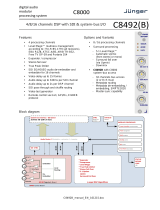
TANDEM-110 architecture
Piggyback option cards determine TANDEM-110 functionality since internal logic is
effectively re-programmed to create the required functions and interconnections whenever
different option cards are fitted.
Changing sub-PCB cards from an input to an output type, or vice versa, will result in a re-
configuration of the TANDEM-110.
An embedder will change to a de-embedder when the card is changed from input to
output, and a de-embedder will change to an embedder when the card is changed from
output to input, the next time power is applied. Any preset memories previously stored
will be lost and may need to be replaced.
The external digital reference is either Word Clock or an AES reference and is only used
for digital output option cards.
The available option cards are:
DIP2 – 2 x AES/EBU inputs for synchronous 48kHz audio, 75 Ohm, 110 Ohm,
HiZ
DIP2RS – 2 x AES/EBU inputs with re-sampler for asynchronous audio (30 to
108kHz), 75 Ohm, 110 Ohm, HiZ
DOP2-110 – 2 x AES/EBU outputs, 110 Ohm balanced, AES reference input
DOP2-75 – 2 x AES/EBU outputs, 75 Ohm unbalanced, AES reference input
AIP2 – Analogue dual stereo audio input
AOP2 – Analogue dual stereo audio output
Control is available from the card edge, active control panels or by serial control from
Statesman, a dedicated software application.

Crystal Vision Introduction
TANDEM-110 User Manual R1.8 6 07/07/2010
1.1 TANDEM-110 configurations
Each side is independent and three configurations are supported, dual de-embedder, dual
embedder or a mixed embedder/de-embedder. Routed audio can be delayed up to 0.68
seconds per side and/or inverted.
Embedder
For each side with an input option card, audio channels can be selected from any four
mono channels available from the input card which can then be routed to any one of the
four available groups in the output SDI stream via that side’s embedder.
TANDEM-110 side 1 with input option
De-embedder
For each side with an output option card, up to four mono audio channels can be selected
from any one of the four groups from that side’s SDI input. These four channels can then
be routed to any of the four mono channels available on the output card.
TANDEM-110 side 2 with output option

Crystal Vision Introduction
TANDEM-110 User Manual R1.8 7 07/07/2010
Mixed embedder/de-embedder
To configure a mixed embedder/de-embedder, an audio input option card fitted in side 1
and an audio output option card fitted into the side 2.
TANDEM-110 with input opt side 1/output opt side 2 -
option card assignment must be as shown for mixed embedder/de-embedder
Routing restrictions
The following routing restrictions apply to a TANDEM-110:
TANDEM-110 does not provide an embedder AND a de-embedder function for
the same SDI data stream - re-embedding of de-embedded data with only one
side is not supported
If there is an input option board, then an embedder function will be provided, if
there is an output option board or NO option card fitted, then a de-embedder
function will be provided
If no option card is fitted, the de-embedder function can only be used by the
Audio Monitoring function via the front PCB jack socket or the monitoring
audio bus rear connector
If only one option card is to be fitted, then that card MUST be on side 1.
TANDEM-110 does not support an input option in SDI 2 and an output option
in SDI 1 - always fit an input option in SDI 1 and an output option in SDI 2
when using an input/output pair – see supported configurations table
Audio and video signals cannot be routed between one SDI circuit and the other
Audio channels must be chosen from within one group when embedding or de-
embedding

Crystal Vision Introduction
TANDEM-110 User Manual R1.8 8 07/07/2010
Supported configurations
The following table shows the supported configurations:
Support Side 1 Side 2
YES Input option (G) + Embed/Mux (C) De-embed/Demux (B) + Output option (J)
NO De-embed/Demux (A) + Output option (I) Input option (H) + Embed/Mux (D)
YES Input option (G) + Embed/Mux (C) Input option (H) + Embed/Mux (D)
YES De-embed/Demux (A) + Output option (I) De-embed/Demux (B) + Output option (J)
NO De-embed/Demux (A/E)* + Embed/Mux(C) De-embed/Demux (B/F)* + Embed/Mux(D)
The card edge control interface uses a condensed code to refer to source and destination
functions when routing audio through the module.
Code Function Code Function
A de-embedder or DEMUX SDI 1 G input option SDI 1
B de-embedder or DEMUX SDI 2 H input option SDI 2
C embedder or MUX SDI 1 I output option SDI 1
D embedder or MUX SDI 2 J output option SDI 2
E No option card on Side 1 F No option card on Side 2
Note: Channel assignments may be altered when monitoring embedded audio.
*If no option cards are fitted Codes E and F appear in the status display at the card edge
to replace de-embedder codes A and B for Side 1 and Side 2 respectively. However the
audio router will still function and monitoring quality de-embedded audio is still output
via the headphone socket and the rear connector – refer to the Monitoring section for
further details.
For more advanced features and functions use the TANDEM-200 which allows
simultaneous embedding and de-embedding and enhanced audio and video routing
functions.

Crystal Vision Introduction
TANDEM-110 User Manual R1.8 9 07/07/2010
1.2 TANDEM-110 functions
Setting audio channel gains
Each TANDEM-110 side is equipped with four channels of variable audio gain to help
compensate for inconsistencies in system levels.
The gain range provided is variable from zero (mute) to eight times unity gain (799%).
Stereo to mono conversion
Facilities are provided to convert stereo or adjacent dual channels to mono. The
conversion works slightly differently, depending on whether an input or output card is
fitted.
If audio channels are derived from an external source via a digital or analogue input card,
the mono function follows the router and any of the four output channels can be set as the
mono sum of its stereo pair.
If audio channels are de-embedded from the incoming SDI signal the mono function
precedes the router and input channels 1&2 and input channels 3&4 can be configured as
either a stereo or mono source prior to being fed to an analogue or digital output card.
Ancillary data
Ancillary data can be placed in both the vertical and horizontal blanking intervals of the
serial component video signal (SDI). The vertical ancillary data space or VANC is used
for such data as VITS or VITC whilst AES/EBU digital audio data is embedded in the
horizontal blanking data interval or HANC.
Data packet management provides controls to choose how new audio packets created for
re-embedding audio are inserted into the HANC data space.
Data packet management provides the following ancillary data handling options:
Support for contiguous HANC data packing
Automatic mark audio group for deletion
Blank entire HANC data space, except the EDH insert
Wide range of formats to embed on all HANC lines or leave a gap around the
vertical switching point
Variable error masking and error handling
Enable or disable EDH processing
Details of HANC processing and EDH processing can be found in the Data Packet
Management chapter.

Crystal Vision Introduction
TANDEM-110 User Manual R1.8 10 07/07/2010
SDI PLL function
There is a single module, like a "time base corrector" that may be inserted into either SDI
1 only, SDI 2 only, or left out of circuit (OFF).
The SDI signal accumulates an ever-increasing amount of jitter as it progresses through
an SDI installation, and as it passes through most equipment in its path. To minimise this
effect, TANDEM-110 has an SDI crystal controlled re-clocker which sets the output SDI
signal to the same mean frequency as the input, but re-clocked by a crystal controlled
Phase Locked Loop [PLL]. This produces extremely low jitter in the SDI output, even in
the presence of a very high level of jitter in the incoming signal. Typically, jitter of 1 or 2
nanoseconds peak to peak will be reduced to a few hundred picoseconds.
The PLL can be placed in either an SDI 1 or SDI 2 input path prior to processing, so all of
the functions of that side, as well as the SDI output, benefit.
Factory defaults
A facility is provided at the card-edge to load ‘factory defaults’ for routing, delay and
preset data into TANDEM’s non-volatile memory. It is strongly recommended that the
appropriate factory defaults be loaded after any of the following:
a change of Mode
whenever sub-PCB cards have been changed
at any time card edge or other menus appear corrupted
Please refer to section 5.2 for details of the available factory defaults that may be recalled.
Note: Always check that the appropriate groups are selected for embedding or de-embedding
after loading defaults (refer to section 5.3 for card edge controls).
Monitoring
TANDEM-110 is equipped with two monitoring outputs:
analogue headphone output
analogue rear connector output
The rear connector output is fed from a monitoring ‘bus’ that may be switched between
silence and a copy of the analogue headphone output.
The rear connector monitoring may be used to extract a ‘breakout’ ‘monitoring quality’
output, even when an output option card is not fitted.
The analogue output can be manually selected as adjacent pairs or routed using the in-
built routing to extract non-adjacent signals from the same group.
External reference
Digital output option cards may be used with an external word clock or AES reference.
Link jumpers are provided on the digital option cards to select 110 Ohm, HiZ or 75 Ohm
impedance.

Crystal Vision Introduction
TANDEM-110 User Manual R1.8 11 07/07/2010
1.3 Rear connector options
TANDEM-110 fits into 2U FR2AV or Indigo frame for up to 12 Crystal Vision modules,
the 1U FR1AV or Indigo frame for up to 6 Crystal Vision modules and a Desk top box for
up to 2 Crystal Vision modules.
There are five different types of rear module to cater for all Crystal Vision frames and to
provide a wide range of I/O options.
RM04 RM07 RM06
12 TANDEMs in 2U, 6 in 1U
Analogue / 110 digital audio
No 2nd SDI output
6 TANDEMs in 2U 3 in 1U
75 digital audio
No 2nd SDI output
6 TANDEMs in 2U 3 in 1U
Analogue / 110 digital audio
2nd SDI output
RM05 RM08 RM36
9 TANDEMs in 2U
Analogue / 110 digital audio
2nd SDI output
9 TANDEMs in 2U
75 digital audio
No 2nd audio or SDI output
6 TANDEMs in 2U 3 in 1U
Analogue / 110 digital audio
2nd SDI output
Further details of the rear modules can be found in the installation chapter
There are five different types of rear module to provide a wide range of I/O options. If
maximum card density is important the slimmest single-width rear connector allows for
12 TANDEM cards in a 2U frame, albeit at the expense of losing the second buffered SDI
outputs. This solution also demands a high-density multiway connector for balanced
digital audio I/O, but all connections, including GPIs and analogue preview monitoring
are available.
However, the loss of second SDI output can be avoided by using a taller rear module. A
double-height single card rear module allows access to all connections at six cards per
frame and a special all-connection triple card rear module achieves nine cards per frame.
There are also double-height single-card and triple-card rear modules available with
BNCs for unbalanced digital audio. However, the double-height version does not have the
second SDI output and the triple does not have the second digital audio outputs.

Crystal Vision Data packet management
TANDEM-110 User Manual R1.8 12 07/07/2010
2 Data packet management
Ancillary data can be placed in both the vertical and horizontal blanking intervals of the
serial component video signal (SDI).
The VANC or Vertical ANCillary data space is used for ancillary data such as VITS or
vertical time code whilst AES/EBU digital audio data is embedded within in the
horizontal blanking data interval or HANC.
Horizontal ancillary data - HANC
Vertical ancillary data - VANC
SAV
EAV
Active video
field 1
SAV
EAV
Active video
field 2
Horizontal ancillary data - HANC
Horizontal ancillary data - HANC
Vertical ancillary data - VANC
Vertical ancillary data - VANC Vertical ancillary data - VANC
SW
POINT
There is room for four groups of AES/EBU digital audio between the end of active video
(EAV) and the start of active video (SAV). A group is comprised of two AES/EBU stereo
signals or four monaural channels.
Each TANDEM-110 ‘side’ can de-embed up to four additional audio channels from one
of the four groups of its SDI input stream or it can embed four audio channels into one of
four possible audio groups in the output SDI stream. Embedding and de-embedding is not
supported by a TANDEM-110 on one side.
The following ancillary data handling options are provided:
Support for contiguous HANC data packing
Automatic mark audio group for deletion
Blank entire HANC data space, except the EDH insert before embedding
Wide range of formats to embed on all HANC lines or leave a gap around the
vertical switching point
Variable error masking and error handling
Enable or disable EDH processing

Crystal Vision Data packet management
TANDEM-110 User Manual R1.8 13 07/07/2010
2.1 HANC processing
Contiguous packing ensures that new audio data packets are embedded at the first free
location after the EAV in the HANC.
Contiguous packing allows for all four groups and other data, such as groups ‘marked for
deletion’ to co-exist sequentially in the HANC. For example, there is only one input audio
group present and it is specifically desired to overwrite it and there is a good reason not to
use Blank HANC.
Blank HANC removes all incoming ancillary data except EDH after the inputs have been
read and before any new data is embedded.
If an incoming audio group is the same as an audio group selected for output in that SDI
path it will normally be flagged as ‘marked for deletion’ so that downstream devices do
not detect that group. However, if there is only one audio group present in the input SDI
stream, then the HANC space is automatically blanked before embedding. This does not
remove any meaningful data, but it leaves only one audio group occupying the HANC
space.
2.2 EDH processing
EDH is in the HANC space one line per field on lines 5 & 318 for 625 and lines 9 & 272
for 525.
EDH processing may be selected to be ‘OFF’ (pass through) or ‘ON’ (include EDH
functions). EDH off/pass through disables the EDH function. When set to ON then the
EDH function calculates and inserts new Active Picture and Full Field EDH values.
If ‘Mark for Deletion’, ‘Blank HANC’ are in place then EDH CRC values will no longer
be valid. In this case, new EDH insert CRC values are calculated and inserted into the
EDH data block in each TV field.

Crystal Vision Data packet management
TANDEM-110 User Manual R1.8 14 07/07/2010
2.3 Vertical switching
When upstream input switching occurs or when input drop-out occurs the embedded
digital audio can suffer degradation and loss of synchronisation. The result could produce
audible defects.
Repeating samples from a buffer during the disturbance can ease the problem or in the
case of upstream switching, lines around the standard switching point can simply be
avoided and not used for digital audio.
There are a number of methods in use for avoiding the switching point suggested in
SMPTE recommendation RP168. SMPTE standards 272M and 291M suggest the use of a
single line gap after the switch point, but larger gaps around the switch point are
sometimes required to provide sufficient robustness. In addition, there is equipment
already in the market place manufactured by Sony before the SMPTE recommendation
was implemented that embeds on all lines. For these reason both SMPTE and proprietary
embedded formats need to be supported.
The card edge display uses the following text to distinguish between the two basic
embedded audio formats:
SMPTE: no data on lines around the preferred switching point e.g. lines 5,6,7,8
in 625 and lines 9,10,11,12 in 525
SONY: data on every line
TANDEM modules provide a range of embedding and de-embedding formats that
provide a trade off between robustness and processing delay.
The de-embedding and embedding formats do not have to be the same. De-embedding
can be set to look at all lines for embedded audio whilst embedding can be done
according to SMPTE recommendations with a switch-point gap.
This allows TANDEM-110 to convert material from SONY formats to SMPTE. It is also
possible to convert SMPTE to SONY format, however, in this case the de-embed mode
should be placed in the special setting of SONY/SMPTE or ‘ALL’ rather than SONY.

Crystal Vision Data packet management
TANDEM-110 User Manual R1.8 15 07/07/2010
Trading process speed for robustness
SONY and SMPTE embed/de-embed modes for the TANDEM-110:
Embed modes
Card edge (Statesman)
Speed >> Robustness >>
SONY1 (Sony audio fifo min) * * * * * * * * * * *
SONY2 (Sony audio fifo short) * * * * * * * * * * *
SONY3 (Sony audio fifo medium) * * * * * * * * * * *
SONY4 (Sony) * * * * * * * * * * *
SMPTE1 (SMPTE audio fifo min) * * * * * * * * * * * *
SMPTE2 (SMPTE audio fifo short) * * * * * * * * * * * *
SMPTE3 (SMPTE audio fifo medium) * * * * * * * * * * * *
SMPTE4 (SMPTE) * * * * * * * * * * * *
De-embed modes
Card edge (Statesman)
Speed >> Robustness >>
SONY1 (Sony audio fifo min) * * * * * * * * * * *
SONY2 (Sony audio fifo short) * * * * * * * * * * *
SONY3 (Sony audio fifo medium) * * * * * * * * * * *
ALL (SMPTE/Sony) * * * * * * * * * * * *
Note: The text in brackets is used by the Statesman PC interface and is the equivalent of the
preceding text displayed at the card edge.
The fastest de-embedding processing results from using SONY1. The slowest and safest
of the de-embedding modes is ‘ALL’, and is recommended when the input cannot be
guaranteed to be always in SONY format.
The fastest embedding mode is also SONY1, since the buffer memory required is the
smallest. SMPTE modes require some extra audio data to be held in a longer queue to
bridge over the vertical switch point gaps. SMPTE4 is the slowest but also the most
robust mode.
If de-embed is set to ANY SONY mode, and the incoming SDI has SMPTE format
embedded audio, it will automatically change to ‘ALL’ de-embed mode within a fraction
of a second. However, there could be some corruption of audio, especially with SONY1
or SONY2 de-embed selected, during a second or two while de-embed mode
automatically changes over. It is strongly recommended NOT to select any SONY de-
embed mode if there is a chance of SMPTE mode inputs, except if the changeover always
occur whilst ‘off-air’.
SONY1 or SONY2 embed and de-embed formats (or SMPTE1 and SMPTE2 formats)
should be avoided if there is likely to be corruption of signals as may occur during SDI or
AES source switching. SONY4 is the most robust, SONY3 is a good compromise
between speed and robustness, and SONY2 is a tighter compromise where speed is of
high importance.
SMPTE embedding formats are more robust than SONY, and SMPTE1 and SMPTE2 are
a relatively tight compromise on robustness where speed of turn round (embed + de-
embed) is very important. The SMPTE4 setting is very robust and can withstand the
highest levels of data corruption. SMPTE3 is a good compromise between speed and
robustness.

Crystal Vision Data packet management
TANDEM-110 User Manual R1.8 16 07/07/2010
De-embed ALL is the most robust of any de-embed settings, and should always be
selected whenever speed of embedding + de-embedding is not critical. Even that turn
round time is relatively short and is unlikely to have adverse effect on the relative timing
of audio to video signals.
It is NOT recommended to change from a lower setting to a faster setting whilst ‘on-air’,
as there may be a momentary corruption of audio briefly just after the change. This
particularly applies to SONY1 and SONY2 de-embedding, and to some degree to
SONY1, SONY2, SMPTE1 and SMPTE2 embedding. Other functions or selections are
more robust and unlikely to result in momentary loss of audio data, but selection changes
should really be applied whilst off-air.
Measuring process delay
Practical measurement of the processing delays associated with the available embedding
and de-embedding formats has been done by configuring one side as an embedder and
feeding the embedded data into the other side configured as a de-embedder.
The following table compares minimum multiplex + de-multiplex transport (or embed +
de-embed turn round) times with the SDI PLL set to OFF for digital and analogue I/O:
Example mode combination Digital delay
DIP2>DOP2
Analog delay
AIP2>AOP2
SONY1 embed + SONY1 de-embed – fastest SONY setting 310µs 1,540µs
SONY4 embed + ALL de-embed – preferred general SONY
setting 830µs 2,070µs
SMPTE1 embed + ALL de-embed – fastest SMPTE setting 670µs 1,900µs
SMPTE4 embed + ALL de-embed – preferred general SMPTE
setting 835µs 2,075µs
Note: Actual times may vary with Mode and other selections.
Changing DPI2+DOP2 to AIP2+AOP2 adds approximately 1,240µs.
SDI in to SDI out is 1.481µs (400 clock cycles at 270 MHz) with SDI PLL set to OFF.
Selecting PLL ON will add a variable amount of delay between 0.6 and 8.9
microseconds, dependent on the severity of jitter and wander of the incoming 270 Mb/s
SDI clock rate.

Crystal Vision Installing Statesman
TANDEM-110 User Manual R1.8 17 07/07/2010
Installing Statesman
The Crystal Vision Statesman PC control software is designed to control a range of
Crystal Vision modules via serial control from a PC.
The main Statesman application communicates with each module in a frame through an
active control panel with a LCD display or a Statesman only panel without a LCD.
Statesman will not be able to detect modules in a frame with only a passive front panel.
2.4 Installing Statesman
Minimum pre-requisites:
A PC running Windows 2000 or Windows XP
A parallel port dongle supplied with the Statesman software package
An RS422 serial connection from the host PC to the RS422 Remote connector
on a Crystal Vision frame with at least one TANDEM110 module and/or other
Statesman compatible module
An active control panel MUST be fitted to the frame with version 1.63 or above
firmware – if it is an Indigo frame the firmware must be V1.04 or above
An optional RS422 to RS232 converter if the PC has no RS422 ports
Installing Statesman
Refer to the readme and/or help file on the CD before proceeding
To view all application windows, set graphics resolution to at least 1024 x 768
Remove any previous version of the Statesman software using the Add/Remove
Programs application in the Windows Control Panel
Ensure that the Statesman dongle is fitted to the parallel port of the host PC
Insert the Statesman CD and the installation should start immediately – if it
does not, run the setup.exe file on the CD
Obey any installation program prompts and restart the PC when prompted
Running Statesman for the first time
The Statesman PC Control System may be run from the Crystal Vision programs folder
via the Start menu or by double-clicking on the Crystal Vision.exe file in the installed
program directory.
When the program runs it will require licence information and an administrator name and
password. It will also need to know which computer port is being used to connect to a
Crystal Vision frame(s).

Crystal Vision Installing Statesman
TANDEM-110 User Manual R1.8 18 07/07/2010
2.5 Statesman operation
Once Statesman is configured it should automatically detect any statesman compatible
modules in the connected frame or frames and display them in the main application left
hand explorer-style window.
Open any frame by clicking on the ‘+’ sign or by double clicking on a frame. Installed
modules should be shown with module icons. Frame and module icons can be named as
desired by right-clicking or using the edit menu and choosing rename.
To aid user recognition of module and frame status quickly, the following colour and size
coding is used:
A module is shown present by full colour and absent by greyed colour
A module is shown open by large icon size and closed by small icon
A module is the source of an active alarm if red and not alarmed if green
Double-clicking on a module will enable the display of the main application menus.
Statesman main application window
The two large control panes shown in the upper and lower halves of the window may be
used to display both TANDEM-110 circuit paths or ‘sides’, two functions such as both
routing tables can be shown for the same ‘side’, or menus for two different modules.
Click on the horizontal button-bar between the two panes to close the lower plane or drag
the button to vary the size of the panes.

Crystal Vision Installing Statesman
TANDEM-110 User Manual R1.8 19 07/07/2010
Warning: Always ensure that the active front panel (if fitted) is in STATESMAN mode. If the front
panel is active, control via Statesman will be subject to high latency and the
response to changes will be slow. For further details of Statesman configuration
please refer to the Statesman manual.
The following card-edge shorthand codes are used for sources and destinations:
Code Function Code Function
A de-embedder SDI 1 G input option SDI 2
B de-embedder SDI 2 H input option SDI 2
C embedder SDI 1 I output option SDI 1
D embedder SDI 2 J output option SDI 2
Audio routing and processing options
The first task to perform when routing audio for the first time is to chose which audio
groups will be involved in de-embedding and embedding. The next task is to decide if any
available external audio sources will be used and if there will be any external audio
destinations. Available external sources and destinations are entirely dependent on the
option cards fitted.
TANDEM-110 as mixed embedder
TANDEM-110 can de-embed any audio channel from any one incoming audio group
from the SDI stream and output it in any digital or analogue channel of an output option
card on the same side. Alternatively, it can embed any audio channel from a digital or
analogue input card into any channel of any one audio group in the outgoing SDI stream
on the same side.
/