
MX-22 & MX-24 LED-Backlit Display
User Manual
displays.agneovo.com

TABLE OF CONTENTS
2
S a f e t y I n f o r m a t i o n
WEEE .......................................................................................................................................................4
EMC Information ......................................................................................................................................5
P r e c a u t i o n s
Notice .......................................................................................................................................................8
Cautions When Setting Up .......................................................................................................................9
Cautions When Using ...............................................................................................................................10
Cleaning and Maintenance .......................................................................................................................10
Notice for the LCD Display .......................................................................................................................11
C h a p t e r 1: P r o d u c t D e s c r i p t i o n
1.1 Package Contents ..............................................................................................................................13
1.2 Wall Mounting Installation Preparation ...............................................................................................14
1.2.1 Wall Mounting ..........................................................................................................................14
1.2.2 Removing the Base Stand.......................................................................................................14
1.3 LCD Display Overview .......................................................................................................................15
1.3.1 Front View and Keypad Buttons ..............................................................................................15
1.3.2 Rear View ................................................................................................................................16
C h a p t e r 2: Ma k i n g C o n n e c t i o n s
2.1 Connecting the Power ........................................................................................................................17
2.2 Connecting Input Source Signals .......................................................................................................18
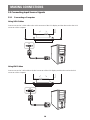
2.2.1 Connecting a Computer ..........................................................................................................18
Using VGA Cables .........................................................................................................................18
Using DVI Cables ...........................................................................................................................18
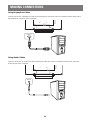
Using DisplayPort Cables ..............................................................................................................19
Using Audio Cables ........................................................................................................................19
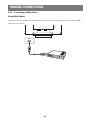
2.2.2 Connecting a Video Device .....................................................................................................20
Using HDMI Cables ........................................................................................................................20
C h a p t e r 3 : U s i n g t h e L C D D i s p l a y
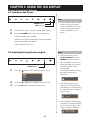
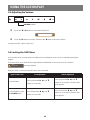
3.1 Turning on the Power .........................................................................................................................21
3.2 Selecting the Input Source Signal ......................................................................................................21
3.3 Adj usting the Volume ..........................................................................................................................22
3.4 Locking the OSD Menu ......................................................................................................................22
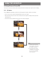
3.5 Using Picture-in-Picture (PIP) ............................................................................................................23
3.5.1 PIP Options .............................................................................................................................23
3.5.2 PIP Swap .................................................................................................................................24
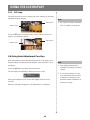
3.6 Using Auto Adj ustment Function ........................................................................................................24
C h a p t e r 4: O n S c r e e n D i s p l a y Me n u
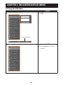
4.1 Using the OSD Menu .........................................................................................................................25
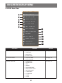
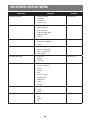
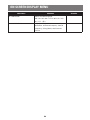
4.2 OSD Menu Tree .................................................................................................................................27

3
TABLE OF CONTENTS
C h a p t e r 5: A d j u s t i n g t h e L C D D i s p l a y
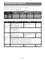
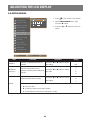
5.1 BRIGHTNESS ....................................................................................................................................30
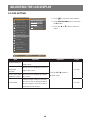
5.2 COLOUR TEMP. .................................................................................................................................32
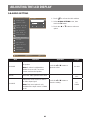
5.3 IMAGE SETTING ...............................................................................................................................33
5.4 ASPECT RATIO ..................................................................................................................................36
5.5 PIP SETTING .....................................................................................................................................37
5.6 ANTI-BURN-IN ...................................................................................................................................39
5.7 OSD SETTING ...................................................................................................................................40
5.8 AUDIO SETTING ................................................................................................................................41
5.9 SYSTEM .............................................................................................................................................42
5.10 ECO SMART ....................................................................................................................................44
5.11 INPUT SELECT ................................................................................................................................45
C h a p t e r 6 : A p p e n d i x
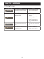
6.1 Warning Messages .............................................................................................................................46
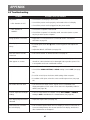
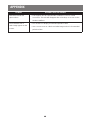
6.2 Troubleshooting ..................................................................................................................................47
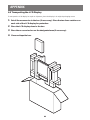
6.3 Transporting the LCD Display ............................................................................................................49
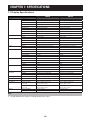
apte 7: Specications
isplay peiains ........................................................................................................................50
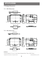
7.2 Display Dimensions ............................................................................................................................51
7.2.1 MX-22 Dimensions ..................................................................................................................51
7.2.2 MX-24 Dimensions ..................................................................................................................51

SAFETY INFORMATION
4
W E E E
Information for users applicable in European Union countries.
e sybl n e prdu r is paaging signies a is prdu as be
disposed separately from ordinary household wastes at its end of life. Please
kindly be aware that this is your responsibility to dispose electronic equipment at
recycling centers so as to help conserve natural resources. Each country in the
European Union should have its collection centers for electrical and electronic
equipment recycling. For information about your recycling drop off area, please
contact your local related electrical and electronic equipment waste management
authority or the retailer where you bought the product.
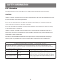
S t a n d a r d T e s t i t e m S t a n d a r d
E N 6 06 01-1-2: 2007
RAD & CON EN55011(EMI)
Harmonic EN61000-3-2
Flicker EN61000-3-3
ESD IEC 61000-4-2: 2008
RS IEC 61000-4-3: 2006+ A1:2007+ A2:2010
EFT IEC 61000-4-4: 2012
Surge IEC 61000-4-5: 2005
CS IEC 61000-4-6: 2008
PFM IEC 61000-4-8: 2009
DIP IEC 61000-4-11: 2004

5
SAFETY INFORMATION
E MC I n f o r m a t i o n
Essential performance of MX-22 and MX-24 is to display images and operate functions normally.
C A U T I O N
The MX-22 and MX-24 requires special precautions regarding EMC and need to be installed,put into service
and used according to the following information.
n use any ables er an e ables a prided r speied by us sing er ables ay
cause the increase of emission or decrease of immunity.
Do not put anyportable and mobileRF communications equipment close to the MX-22 and MX-24. Doing
so may affect the MX-22 and MX-24.
The MX-22 and MX-24 should not be used adj acent to or stacked with other equipment. If adj acent or
stacked use is necessary ,the equipment or system should be observed to verify normal operation in the
ngurain in i i ill be used
nyne nnes addiinal euipen e signal inpu par r signal upu parsnguring a
medical system, responsible that the system complies with the requirements of IEC/ EN60601¬ 1¬ 2.
Guidance and manufacturer’s declaration – electromagnetic emissions
e and is inended fr use in e eleragnei enirnen speied bel e
customer or the user of the MX-22 and MX-24 should assure that it is used in such an environment. Not
Life-supporting Medical Equipment.
Emissions test Electromagnetic environment – guidance
Harmonic emissions
IEC/EN61000-3-2
Class A
The MX-22 and MX-24 is suitable for use in all
establishments,including domestic establishments
and those directly connected to the public low-voltage
power supply network that supplies buildings used for
domestic pur poses.
lage uuains /
ier eissins
EN61000-3-3
Class A

6
SAFETY INFORMATION
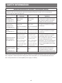
G u i d a n c e a n d m a n u f a c t u r e r ’ s d e c l a r a t i o n – e l e c t r o m a g n e t i c i m m u n i t y
e and is inended fr use in e eleragnei enirnen speied bel e
customer or the user of The MX-22 and MX-24 should assure that it is used in such an environment.
Not Life-supporting Medical Equipment.
I m m u n i t y t e s t I E C / E N 6 06 01
t e s t l e v e l
C o m p l i a n c e l e v e l E l e c t r o m a g n e t i c e n v i r o n m e n t –
g u i d a n c e
Electrostatic
discharge (ESD)
IEC/EN61000-4-2
± 6kV contact
± 8kV air
± 6kV contact
± 8kV air
Floors should be wood, concrete
r erai ile f rs are ered
with synthetic material, the relative
humidity should be at least 30%.
Electrical fast
transient / burst
IEC/EN61000-4-4
± 2kV for power
supply lines
± 1kV for input/output
lines
± 2kV for power
supply lines
± 1kV for input/output
lines
Mains power quality should be that
of a typical commercial or hospital
environment.
Surge
IEC/EN61000-4-5
± 1kV line(s) to line(s)
± 2kV line(s) to earth
± 1kV line(s) to line(s)
± 2kV line(s) to earth
Mains power quality should be that
of a typical commercial or hospital
environment.
lage uuains
ier eissins
IEC/EN61000-3-3
<5% UT (>95% dip in
UT) for 0.5 cycle
40% UT (60% dip in
UT) for 5 cycles
70% UT (30% dip in
UT) for 25 cycles
<5% UT (>95% dip in
UT) for 5 sec.
<5% UT (>95% dip in
UT) for 0.5 cycle
40% UT (60% dip in
UT) for 5 cycles
70% UT (30% dip in
UT) for 25 cycles
<5% UT (>95% dip
in UT) for 5 sec.
Mains power quality should be that
of a typical commercial or hospital
environment. If the user of the
MX-22 and MX-24 requires continued
operation during power mains
interruptions, it is recommended that
the MX-22 and MX-24 be powered
from an uninterruptible power supply
or a battery.
Power frequency
(50/60Hz) magnetic
eld
IEC/EN61000-4-8
3A/m 3A/m
er freueny agnei elds
should be at levels characteristic
of a typical location in a typical
commercial or hospital environment.
N O T E : UT is the a.c. mains voltage prior to application of the test level.
Mains power quality should be that of a typical commercial or hospital environment. If the user of the MX-22,
MX-24 requires continued operation during power mains interruptions, it is recommended that the MX-22
MX-24 be powered from an uninterruptible power supply or a battery.

7
SAFETY INFORMATION
E S D d e c l a r a t i o n s t a t e m e n t
ere are ier disurbane n e sreen during e es bu au reer afer e es is perissie
lss f perfrane is speied by e anufaurer and is penena ill be pu as a lear saeen in
the User’s Manual to avoid misunderstanding.
D I P d e c l a r a t i o n s t a t e m e n t
The EUT power off during the test, but self- recover after the test. This permissive loss of performance is
speied by e anufaurer and is penena ill be pu as a lear saeen in e sers anual
avoid misunderstanding.
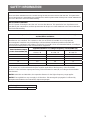
R e c o m m e n d e d s e p a r a t i o n d i s t a n c e s b e t w e e n p o r t a b l e a n d m o b i l e R F c o m m u n i c a t i o n s e q u i p m e n t
a n d t h e MX-22 a n d MX-24
The MX-22 and MX-24 is intended for use in an electromagnetic environment in which radiated RF
disturbances are controlled. The customer or the user of the MX-22 and MX-24 can help prevent
electromagnetic interference by maintaining a minimum distance between portable and mobile RF
communications equipment (transmitters) and the MX-22 and MX-24 as recommended below, according to
the maximum output power of the communications equipment.
R a t e d m a x i m u m o u t p u t
p o w e r o f t r a n s m i t t e r ( W )
S e p a r a t i o n d i s t a n c e a c c o r d i n g t o f r e q u e n c y o f t r a n s m i t t e r ( m )
150k H z t o 8 0MH z
1.2
8 0MH z t o 8 00MH z
1.2
8 00MH z t o 2. 5G H z
2.
0.01 0.12 0.12 0.23
0.1 0.38 0.38 0.73
1 1.2 1.2 2.3
10 3.8 3.8 7.3
100 12 12 23
For transmitters rated at a maximum output power not listed above, the recommended separation distance
“ d” in meters (m) can be estimated using the equation applicable to the frequency of the transmitter,
where “ P” is the maximum output power rating of the transmitter in watts (W) according to the transmitter
manufacturer.
N O T E 1 At 80 MHz and 800 MHz, the separation distance for the higher frequency range applies.
N O T E 2 These guidelines may not apply in all situations. Electromagnetic propagation is affected by
absrpin and reein fr sruures bes and peple
C a b l e l e n g t h
Power Cord : Accessory 1.8m

PRECAUTIONS
8
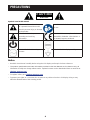
CAUTION
RISK OF ELECTRIC SHOCK
DO NOT OPEN
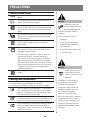
S y m b o l s u s e d i n t h i s m a n u a l
This icon indicates the existence
of a potential hazard that could
result in personal inj ury or damage
to the product.
ISO 7010-M002: Follow instructions
for use
This icon indicates important
operating and servicing
information.
This icon indicates complies with the
93/42/EEC, EN60601-1, EN 60601-1-2
of related European standards.
IEC 60417 -5009 : STAND- BY IEC 60417 -5031 : Direct Current
IEC 60417 -5032: Alternating
Current.
IEC 60417 -5021: Equipotentiality
N o t i c e
• Read this User Manual carefully before using the LCD display and keep it for future reference.
• e prdu speiains and er infrain prided in is ser anual are fr referene nly ll
information is subj ect to change without notice. Updated content can be downloaded from our web site at
d i s p l a y s . a g n e o v o . c o m .
• To register online, go to d i s p l a y s . a g n e o v o . c o m .
• To protect your rights as a consumer, do not remove any stickers from the LCD display. Doing so may
affect the determination of the warranty period.

9
PRECAUTIONS
C a u t i o n s W h e n S e t t i n g U p
Do not place the LCD display near heat sources, such as a heater, exhaust vent, or in direct
sunlight.
Do not cover or block the ventilation holes in the housing.
Place the LCD display on a stable area. Do not place the LCD display where it may subj ect
to vibration or shock.
Place the LCD display in a well-ventilated area.
Do not place the LCD display outdoors.
Do not place the LCD display in a dusty or humid environment.
Do not spill liquid or insert sharp obj ects into the LCD display through the ventilation holes.
ing s ay ause aidenal re eleri s r daage e display

10
PRECAUTIONS
C a u t i o n s W h e n U s i n g
Use only the power cord supplied with the LCD
display.
The power outlet should be installed near the LCD
display and be easily accessible.
If an extension cord is used with the LCD display,
ensure that the total current consumption plugged
into the power outlet does not exceed the ampere
rating.
Do not allow anything to rest on the power cord. Do
not place the LCD display where the power cord
may be stepped on.
f e display ill n be used fr an indenie
period of time, unplug the power cord from the
power outlet.
To disconnect the power cord, grasp and pull by the
plug head. Do not tug on the cord; doing so may
ause re r eleri s
The mains plug or appliance coupler is used as
the disconnect device, the disconnect device
shall remain readily operable. Always completely
disconnect the power cord set from your product
whenever you are working or cleaning on it. Do not
make connections while the power is on, because
a sudden rush of power can damage sensitive
electronic components.
Do not unplug or touch the power cord with wet
hands.
C l e a n i n g a n d Ma i n t e n a n c e
Disconnect this equipment from any AC outlet before cleaning.
Do not use liquid or spray detergents for cleaning.
Use a damp cloth. Keeping to clean your monitor by monthly.
The LCD display comes with NeoV
TM
Optical Glass.
Use a soft cloth to clean the glass surface and the
housing. The display can be cleaned using a cloth
moistened with 95% ethyl alcohol.
Do not rub or tap the surface of the glass with sharp
or abrasive items such as a pen or screwdriver. This
may result in scratching the surface of the glass.
Do not attempt to service the LCD display yourself,
refer ualied serie persnnel pening r
removing the covers may expose you to dangerous
voltage or other risks.
W a r n i n g :
Unplug the power cord
from the power outlet and
refer ualied serie
personnel under the following
conditions:
♦ When the power cord is
damaged.
♦ If the LCD display has been
dropped or the housing has
been damaged.
♦ If the LCD display emits smoke
or a distinct odor.
W a r n i n g :
Ceiling mount or mount
on any other horizontal
surface overhead are not
advisable.
Installation in contravention of
the instructions may result in
undesirable consequences,
particularly hurting people and
damaging property. Users who
have already mounted the
display on the ceiling or any
other horizontal surface overhead
are strongly advised to contact
AG Neovo for consultations and
solutions to help ensure a most
pleasurable and fullling display
experience.

11
PRECAUTIONS
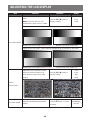
N o t i c e f o r t h e L C D D i s p l a y
In order to maintain the stable luminous performance, it is recommended to use low brightness setting.
Due to the lifespan of the lamp, it is normal that the brightness quality of the LCD display may decrease
with time.
When static images are displayed for long periods of time, the image may cause an imprint on the LCD
display. This is called image retention or burn-in.
To prevent image retention, do any of the following:
• Set the LCD display to turn off after a few minutes of being idle.
• Use a screen saver that has moving graphics or a blank white image.
• Switch desktop backgrounds regularly.
• Adj ust the LCD display to low brightness settings.
• Turn off the LCD display when the system is not in use.
Things to do when the LCD display shows image retention:
• Turn off the LCD display for extended periods of time. It can be several hours or several days.
• Use a screen saver and run it for extended periods of time.
• Use a black and white image and run it for extended periods of time.
When the LCD display is moved from one room to another or there is a sudden change from low to high
ambient temperature, dew condensation may form on or inside the glass surface. When this happens, do
not turn on the LCD display until the dew disappears.
Due to humid weather conditions, it is normal for mist to form inside the glass surface of the LCD display.
The mist will disappear after a few days or as soon as the weather stabilizes.
There are millions of micro transistors inside the LCD display. It is normal for a few transistors to be
damaged and to produce spots. This is acceptable and is not considered a failure.
The intended use of the MX-22,MX-24 is to serve as a LCD monitor for integration with the hospital system.
It is designed for general purpose for adults using at hospital environment,continuous operation. For
displaying and viewing of images for reference. The use of this device does not require any direct contact
with patients.
Accessory equipment connected to the analog and digital interfaces must be in compliance with the
respective nationally harmonized IEC standards (i.e. IEC 60950 for data processing equipment, IEC 60065
for video equipment, IEC 61010-1 for laboratory equipment, and IEC 60601-1 for medical equipment.)
urerre all ngurains sall ply i e syse sandard erybdy
nnes addiinal euipen e signal inpu par r signal upu par ngures a edial syse
and is therefore, responsible that the system complies with the requirements of the system standard
e uni is fr elusie inernnein i eried euipen in e paien
enirnen and eried euipen uside f e paien enirnen f in dub nsul e
technical services department or your local representative.
Grounding reliability can only be achieved when the equipment is connected to an equivalent receptacle
marked “ Hospital Only” or “ Hospital Grade”.

12
PRECAUTIONS
N o t i c e f o r t h e L C D D i s p l a y
Use a power cord that matches the voltage of the power outlet, which has been approved and complies
with the safety standard of your particular country.
The single device output analog signals through ADC element (Analog DigitalConvert) conversion to
become a digital signal and the video signal is via Video Decorder conversion. It has become the same
digital signal, these signals via Scaler IC as zoom in or out action and digital image processing, then
through the cable line transmission LVDS signals to one of the LCD module. The last by the clock controller
(Timing Controller, TCON), the clock signal is transmitted to the drive IC on the panel and turn on Backlight
for LCD module light source by Scaler control.
W A R N I N G – No protection against the ingress of water : IPX0
W A R N I N G – Do not modify this equipment without authorization of the manufacturer.
Installation and OSD adj usting should only be carried by manufacturer trained and authorized personnel.
W A R N I N G – To avoid risk of electric shock, this equipment must only be connected to a supply mains with
protective earth.
C A U T I O N : This adapter Manufacturer/model is a forming part of the medical device.
♦ Power by class I power supply.
♦ Adapter manufacturer/model:.
ADAPTER TECH: ATM065-P120/ATM065T-P120
Input/output: 100-240V~ 50-60Hz, 12V(
) 5A.
EDAC TECH:EM10681G
Input/output: 100-240V~ 50-60Hz, 12V( ) 4.16A.
W A R N I N G : Use suitable mounting apparatus to avoid risk of inj ury.
W A R N I N G : e euipen n suiable fr use in e presene f a aable anesei iure i air
or with oxygen or nitrous: Not AP or APG Category
C A U T I O N : No applied part.
Make sure the user not to contact SIP/SOPs and the patient at the same time.
C A U T I O N : ranspr suld nly be underaen in a a surfae

13
CHAPTER 1: PRODUCT DESCRIPTION
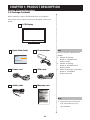
1. 1 P a c k a g e C o n t e n t s
When unpacking, check if the following items are included in
the package. If any of them is missing or damaged, contact your
dealer.
Q u i c k S t a r t G u i d e
P o w e r c o r d
N o t e :
♦ The pictures are for reference
only. Actual items may vary
upon shipment.
V G A c a b l e
P o w e r a d a p t e r
L C D D i s p l a y
A u d i o c a b l e
N o t e :
Must use only the supplied power
adapter:
♦ Adaptor Technology
Model no.: ATM065-P120
Rating: 12V/5A
♦ Adaptor Technology
Model no.: ATM065T-P120
Rating: 12V/5A
♦ EDAC Technologies Corporation
Model no.: EM10681G
Rating: 12V/4.16A
C h a p t e r 1: P r o d u c t D e s c r i p t i o n
W a r r a n t y c a r d
MX-22 & MX-24
www.agneovo.com
MX-22/MX-24_Quick Guide_V010
Quick Start Guide
MX-22 & MX-24 LED-Backlit Display

14
PRODUCT DESCRIPTION
1. 2 W a l l Mo u n t i n g I n s t a l l a t i o n P r e p a r a t i o n
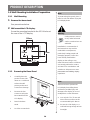
1. 2. 1 W a l l Mo u n t i n g
1 R e m o v e t h e b a s e s t a n d .
See procedures below.
2 W a l l m o u n t t h e L C D d i s p l a y .
Screw the mounting bracket to the VESA holes at
the rear of the LCD display.
100
mm
75
mm
100
mm
75
mm
1. 2. 2 R e m o v i n g t h e B a s e S t a n d
1 Carefully place the
product screen side
down on a cushioned
surface that will
protect product and
screen from damage.
2 Remove the four
screws securing the
base stand from the
LCD display.
3 Detach the base
stand.
4 Lock four screws back.
N o t e :
Take measures to prevent the
LCD display from falling down
and lessen possible inj ury and
damage to the display in case of
earthquakes or other disasters.
♦ Use only the 75 x 75 mm and
100 x 100 mm wall mount kit
recommended by AG Neovo.
♦ Secure the LCD display on a
solid wall strong enough to bear
its weight.
N o t e :
To protect the glass panel, place a
towel or soft cloth before laying the
LCD display down.
W a r n i n g :
Ceiling mount or mount
on any other horizontal
surface overhead are not
advisable.
Installation in contravention of
the instructions may result in
undesirable consequences,
particularly hurting people and
damaging property. Users who
have already mounted the
display on the ceiling or any
other horizontal surface overhead
are strongly advised to contact
AG Neovo for consultations and
solutions to help ensure a most
pleasurable and fullling display
experience.

15
PRODUCT DESCRIPTION
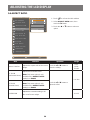
1. 3 L C D D i s p l a y O v e r v i e w
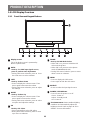
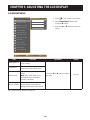
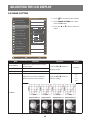
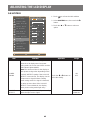
1. 3 . 1 F r o n t V i e w a n d K e y p a d B u t t o n s
1
64 75 982 3
S O U R C E
• Press to select the input signal source.
U P
Hot Key: PIP Select
• Press repeatedly to select PIP option.
• During OSD menu selection, press to move
up a menu or submenu.
ME N U
• Press to display the OSD menu.
• Press again to hide the OSD menu.
D O W N
Hot Key: DICOM Mode Select
• When PIP is on, press to SWAP the PIP
main and sub picture.
• When PIP is off, press to select picture
mode (STANDARD/DICOM)
• During OSD menu selection, press to move
down a menu or submenu.
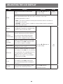
L E F T
Hot Key: Volume Down
• Press to display the volume screen. Then
press again to decrease the volume.
• During OSD menu selection, press to adjust
the settings.
R I G H T
Hot Key: Volume Up
• Press to display the volume screen. Then
press again to increase the volume.
• During OSD menu selection, press to select
an option and adj ust the settings.
A U T O
Hot Key: For VGA input signal source,
press to perform auto adjustment.
• During OSD menu selection, press to close
the OSD menu or exit a submenu.
D i s p l a y s c r e e n
The LCD display screen is protected by
NeoV
TM
Optical Glass.
1
7
6
5
4
3
2
8
P O W E R / L E D i n d i c a t o r
• Press to turn the power on or off.
Green - Power on
Amber - Standby mode
Off - Power off
9
E c o S m a r t s e n s o r : Detect ambient lighting
conditions and automatically adj ust the
brightness levels. Refer to page 46 “ ECO
SMART” for more information.
10
10

16
PRODUCT DESCRIPTION
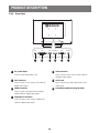
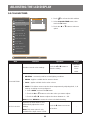
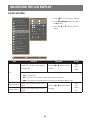
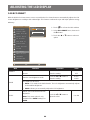
1. 3 . 2 R e a r V i e w
AUDIO INDVI HDMI DisplayPort VGA
DC IN
1
1
D C p o w e r i n p u t
Use to connect the power cord.
5
V G A c o n n e c t o r
Use to connect a PC using a VGA cable for
analogue input signal.
2
D V I c o n n e c t o r
Use to connect a PC using a DVI cable for
digital input signal.
6
A u d i o p o r t
Use to connect an audio cable for the PC’s
audio input.
3
H D MI c o n n e c t o r
Use to connect an input device using an
HDMI cable for digital input signal.
7
P o t e n t i a l E q u a l i za t i o n P l u g ( Ø 6 m m )
4
D i s p l a y P o r t c o n n e c t o r
Use to connect a PC using a DisplayPort
cable for digital input signal.
3
4 5
6
2
7

17
CHAPTER 2: MAKING CONNECTIONS
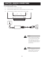
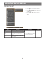
2. 1 C o n n e c t i n g t h e P o w e r
1 Connect the power cord to the power adapter.
2 Connect the power adapter to the DC power input at the rear of the LCD display.
3 Connect the power cord plug to a power outlet or a power supply.
DC IN
C a u t i o n :
♦ Make sure that the LCD display is
not connected to the power outlet
before making any connections.
Connecting cables while the power
is ON may cause electric shock or
personal inj ury.
C a u t i o n :
♦ When unplugging the power cord,
hold the power cord by the plug
head. Never pull by the cord.
C h a p t e r 2: Ma k i n g C o n n e c t i o n s

18
MAKING CONNECTIONS
2. 2 C o n n e c t i n g I n p u t S o u r c e S i g n a l s
2. 2. 1 C o n n e c t i n g a C o m p u t e r
U s i n g V G A C a b l e s
Connect one end of a VGA cable to the VGA connector of the LCD display and the other end to the VGA
connector of the computer.
VGA
U s i n g D V I C a b l e s
Connect one end of a DVI cable to the DVI connector of the LCD display and the other end to the DVI
connector of the computer.
DVI

19
MAKING CONNECTIONS
U s i n g D i s p l a y P o r t C a b l e s
Connect one end of a DisplayPort cable to the DisplayPort connector of the LCD display and the other end to
the DisplayPort connector of the computer.
DisplayPort
U s i n g A u d i o C a b l e s
Connect one end of an audio cable to the audio port at the rear of the LCD display and the other end to the
audio out port of the computer.
AUDIO IN

20
MAKING CONNECTIONS
2. 2. 2 C o n n e c t i n g a V i d e o D e v i c e
U s i n g H D MI C a b l e s
Connect one end of an HDMI cable to the HDMI connector of the LCD display and the other end to the HDMI
connector of your device.
HDMI
Page is loading ...
Page is loading ...
Page is loading ...
Page is loading ...
Page is loading ...
Page is loading ...
Page is loading ...
Page is loading ...
Page is loading ...
Page is loading ...
Page is loading ...
Page is loading ...
Page is loading ...
Page is loading ...
Page is loading ...
Page is loading ...
Page is loading ...
Page is loading ...
Page is loading ...
Page is loading ...
Page is loading ...
Page is loading ...
Page is loading ...
Page is loading ...
Page is loading ...
Page is loading ...
Page is loading ...
Page is loading ...
Page is loading ...
Page is loading ...
Page is loading ...
-
 1
1
-
 2
2
-
 3
3
-
 4
4
-
 5
5
-
 6
6
-
 7
7
-
 8
8
-
 9
9
-
 10
10
-
 11
11
-
 12
12
-
 13
13
-
 14
14
-
 15
15
-
 16
16
-
 17
17
-
 18
18
-
 19
19
-
 20
20
-
 21
21
-
 22
22
-
 23
23
-
 24
24
-
 25
25
-
 26
26
-
 27
27
-
 28
28
-
 29
29
-
 30
30
-
 31
31
-
 32
32
-
 33
33
-
 34
34
-
 35
35
-
 36
36
-
 37
37
-
 38
38
-
 39
39
-
 40
40
-
 41
41
-
 42
42
-
 43
43
-
 44
44
-
 45
45
-
 46
46
-
 47
47
-
 48
48
-
 49
49
-
 50
50
-
 51
51


Ask a question and I''ll find the answer in the document
Finding information in a document is now easier with AI
Related papers
Other documents
-
Baaske Medical XM-24W User manual
-
Hyundai U90 User manual
-
Fresca FVN1053 Installation guide
-
-
-
Vive 2QBB100 User manual
-
-
-
-