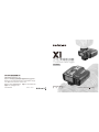
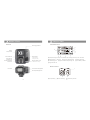
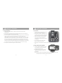
Godox X1C is a versatile wireless flash trigger that offers a range of features to enhance your photography workflow. With multi-channel triggering, stable signal transmission, and sensitive reaction, it provides photographers with unparalleled flexibility and control over their lighting setups. The X1C is compatible with Canon EOS series cameras and cameras with PC sync sockets. It enables high-speed synchronization with most camera flashes that support E-TTL II, with a maximum flash synchronization speed of up to 1/8000s.
Godox X1C is a versatile wireless flash trigger that offers a range of features to enhance your photography workflow. With multi-channel triggering, stable signal transmission, and sensitive reaction, it provides photographers with unparalleled flexibility and control over their lighting setups. The X1C is compatible with Canon EOS series cameras and cameras with PC sync sockets. It enables high-speed synchronization with most camera flashes that support E-TTL II, with a maximum flash synchronization speed of up to 1/8000s.


-
 1
1
-
 2
2
-
 3
3
-
 4
4
-
 5
5
-
 6
6
-
 7
7
-
 8
8
-
 9
9
-
 10
10
-
 11
11
-
 12
12
-
 13
13


Godox X1C is a versatile wireless flash trigger that offers a range of features to enhance your photography workflow. With multi-channel triggering, stable signal transmission, and sensitive reaction, it provides photographers with unparalleled flexibility and control over their lighting setups. The X1C is compatible with Canon EOS series cameras and cameras with PC sync sockets. It enables high-speed synchronization with most camera flashes that support E-TTL II, with a maximum flash synchronization speed of up to 1/8000s.
Ask a question and I''ll find the answer in the document
Finding information in a document is now easier with AI
Related papers
-
Godox XT32C Owner's manual
-
-
-
-
-
Godox Godox V1-C Flash User manual
-
Godox 4331907336 User manual
-
-
-
Other documents
-
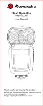 Powerextra 8595760230 User manual
-
Cheetah cl-360x User manual
-
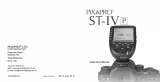 Pixapro ST-IV PRO TTL Flash Trigger User manual
-
-
Yongnuo YN-622C-TX User manual
-
Yongnuo YN-622C Datasheet
-
-
 Strobies Pro-Flash Tli-C User manual
-
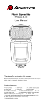 Powerextra 8595765798 User manual
-
 Neewer 10036052 User guide


