Troubleshooting
If there is a problem, refer to this Troubleshooting Guide.
The Camera Flash does not fire.
● The camera flash is not attached securely to the camera.
→Attach the camera’s mounting foot securely to the camera.
● The electrical contacts of the Camera Flash and camera are dirty.
→Clean the contacts.
● < > or < > is not displayed in the view finder of camera.
→Wait until the flash is fully recycled and the flash ready indicator
lights up.
→If the flash ready indicator lights up, but < > or < > is not
displayed in the view finder, check whether this flash unit is
securely attached to the camera hotshoe.
→If the flash ready indicator does not light up after a long wait,
check whether the battery power is enough. If the battery power
is low, < > will appear and blink on the LCD panel. Please
replace the battery immediately.
The power turns off by itself.
● After 90 seconds of idle operation, auto power off took effect if the
flash is set as master.
→Press the shutter button halfway or press any flash button to
wake up.
● After 60 minutes (or 30 minutes) of idle operation, the flash unit
will enter sleep mode if it is set as slave.
→Press any flash button to wake up.
Auto zoom does not work.
● The camera flash is not attached securely to the camera.
→Attach the camera flash’s mounting foot to the camera.
The flash exposure is underexposed or overexposed.
● There was a highly reflective object (e.g. glass window) in the
picture.
→Use FE lock (FEL).
● You used high-speed sync.
→With high-speed sync, the effective flash range will be shorter.
Make sure the subject is within the effective flash range
displayed.
● You used Manual Flash mode.
→Set the flash mode to ETTL or modify the flash output.
Photos have dark corners or only parts of the target subject
are illuminated.
● The focal length of lens exceeds the flash coverage.
→Check the flash coverage you set. This flash unit has the flash
coverage between 28 and 105mm, which fits medium-format
cameras.
Firmware Upgrade
● The USB port is a Type-C USB socket. Type-C USB connection
line is applicable.
● As the firmware upgrade needs the support of Godox G3
software, please download and install the "Godox G3 firmware
upgrade software" before upgrading. Then, choose the related
firmware file.
● As the product needs to do firmware upgrade, please refer to
instruction manual of the newest electric version as final.
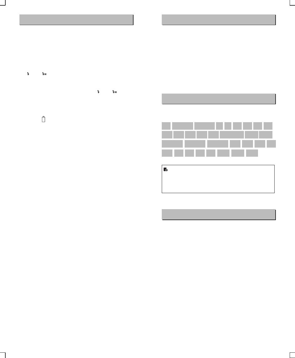
Compatible Camera Models
This flash unit can be used on the following Canon EOS series
camera models:
This table only lists the tested camera models, not all Canon
EOS series cameras. For the compatibility of other camera
models, a self-test is recommended.
Rights to modify this table are retained.
● Shut down the device immediately should abnormal operation be
detected.
● Avoid sudden impacts and the product should be dedusted
regularly.
● It is normal for the flash tube to be warm when in use. Avoid
continuous flashes if unnecessary.
● Maintenance of the flash must be performed by our authorized
maintenance department which can provide original accessories.
● This product, except consumables e.g. flash tube, is supported
with a one-year warranty.
● Unauthorized service will void the warranty.
● If the product had failures or was wetted, do not use it until it is
repaired by professionals.
● Changes made to the specifications or designs may not be
reflected in this manual.
Maintenance
5D Mark IV 7D Mark II 6D Mark II 760D 750D 70D 80D
77D M5 M3 M50800D
5D Mark III 5D Mark II
6D
7D
60D 50D 40D
30D
650D 600D 550D 500D 450D
400D Digital
1100D 1000D
1DX
EOS R
1500D 3000D
- 59 -
- 60 -