
Kenmore 2500
15 GALLON
CENTRAL HUMIDIFIER
Installation
Maintenance
Repair Parts
Troubleshooting
Sears, Roebuck and Co., Hoffman Estates, IL 60179 U.S.A.

contents
WARRANTY ........................................... 2
BEFORE YOU START
Rules for Safe Installation
and Operation ................................... 2
Tools and Materials Needed .................. 2
UNDERSTANDING HUMIDITY .............. 3
SELECTING A LOCATION ..................... 4
INSTALLATION ...................................... 4
DISASSEMBLY ...................................... 4
WATER SUPPLY ................................... 6
HUMIDISTAT.......................................... 8
OPERATI_)N .......................................... 9 _
MAINTENANCE..................................... 9
SERVICE HINTS .................................. 10
REPAIR PARTS.................................... 11
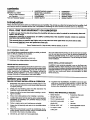
introduction
Please read the instructions before you install and use your humidifier.This will help you obtain the full value from the humidifier. It will
also help you avoid any needless service cost, ifthe problem is something we cannot control and cannot cover in our Warranty.
FULL ONE YEAR WARRANTY ON HUMIDIFIER
If, within one year from the date of purchase, this humidifier falls due to a defect In material or workmanship, Sears will
repair It, free of charge.
WARRANTY SERVICE IS AVAILABLE BY SIMPLY CONTACTING THE NEAREST SEARS STORE OR SERVICE
CENTER IN THE UNITED STATES.
This warranty gives you specific legal rights, and you may also have other rights which vary from state to state.
This warranty DOES NOTcover the replacement media pad.
Seam, Roebuck and Co., Dept. 817WA, Hoffman Estates, IL 60179
DO-IT-YOURSELF CHECK LIST
Ifyou feel the following operations are withinyour skills, you should
have no difficulty installing this humidifier.
[] Cutting and ddlling sheet metal.
[] Using hand tools: screwdriver, wrench, etc.
[] Hooking up low voltage electdcal connections.
SEARS INSTALLATION POLICY
AllinstallationlaborarrangedbySearswillbeperformedina neat,
workmanlikemannerinaccordancewithgenerallyacceptedtrade
practices.Further,all installationswillcomplywithall locallaws,
codes, regulations,and ordinances.The customerwillalso be
protected,dudnginstallation,by insurancerelatingto property
damage,Workman'sCompensation,and publicliability.
Youmustrealizethatthewrong useof any toolcan be danger-
ous. Be sureyou knowhow to use the toolsand equipmentto
avoidany possiblehazards.If you haveany doubtwe ask that
youcontactyourSearssalesperson.They willarrangeforprofes-
sionalinstallation.
SEARS INSTALLATION WARRANTY
In additionto any warrantyextendedto you on the Sears mer-
chandiseinvolved,whichwarrantybecomes effectivethe date
themerchandiseisinstalled,shouldtheworkmanshipofanySears
arrangedinstallationprovefaultywithinoneyear,Searswill,upon
noticefrom you, cause suchfaults to be correctedat no addi-
tionalcast toyou.
before you start
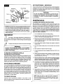
RULES FOR SAFE INSTALLATION & OPERATION
1. Read these rules and the instructions carefully. Failure to fol-
low the rules and instructions could cause bodily injury and/
or property damage.
2. Check your local building codes and utility standards. The
installation must comply with their rules.
3. Always shut offthe furnace blower before installing or servic-
ing the humidifier.
4. Always wear safety glasses when installing or servicing.
5. HUMIDIFIER MUST NOT BE INSTALLED IN AREAWHERE
FREEZING IS POSSIBLE OR LEAKING WOULD CAUSE
WATER DAMAGE.
6. Follow a regular service and maintenance schedule.
7. Always shut off electricity and water to the humidifier before
servicing.
8. When the furnace blower is used for air-conditioning, the hu-
midifier damper should be closed, and the humidistat should
be turned to the minimum humidity setting.
9. NEVER OILANY PARTOFTHE HUMIDIFIER.
10. Topreventoverhumidification,humidifiermustnotbe oper-
ated above humidistat high position or above the +20
position (whichever applies) except briefly to test op-
eration after installation or servicing.
TOOLS AND MATERIALS NEEDED
• Safety Glasses
• Straight edge ruler
• Pencil or grease pencil
• Hand ddll or grounded
electric drill
• Ddll bits, 5/32", 1/8"
• Tin snips or metal
cutting saw
• Screwdriver (flat point,
medium size)
• File
Level
• Hammer
• Small adjustable wrench
• Center punch

THANK YOU! ....
Thankyouforselecting a SearsHumidifier.Itwillprovideyearsofsarvlca ffyougiveita littlecare.
UNDERSTANDING HUMIDITY
Humiditycan be puzzling. It cannot be seen, heard, touched,
smelledortasted. Many peopledo notunderstandwhata humidi-
fier willor willnotdo.
Probablythe bestway tojudge whetherthe humidityistoo high,
too loworaboutdghtistowatchyourwindows.Iftheyare heavily
fogged you mostlikelyhavetoo much.Ifthere is no moistureon
themat all, especiallyin the comers,you have too little.(NOTE:
Moisturewill notnormallyformon thermopaneor whenstormwin-
dowsare used.)If there issome moisture in the windowcomers
andalongthe edges,the humidityisJustaboutright.This isa good
rule of thumb, if you do not have an expensivepiece of testing
equipment.Yourcomfort isanothergoodcheck.
TYPICAL QUESTIONS ASKED
1. Why do moisture requirements vary from home to home?
Requirements depend on the amount and dryness of air to be
humidified. The larger and more loosely constructed the home,
the greater the quantity of moisture required.
5. What else causes static shock besides low humidity?
Some types of carpets tend to create more static than others.
While the proper humidity level will reduce the static level, it
may not eliminate static entirely.
2. How can I best check my home's relative humidity?
Firstgive your humidifiertime to buildup the humidityto an
acceptablelevel.Instrumentsareavailabletomeasurerelative
humidity,but from a practicalstandpoint,yourcomfortis the
bestguide.Youcannotdependon table top or wall hungdial
gauges.
3. How long will It take my humidifier to build up the
humidity In my home?
Much depends on the outside temperature, time of year, home
construction, and how dded out the home has become. In some
cases, it may take a week or more.
4. What are some of the common things that cause higher
than average air leakage In the home, therefore causing
low humidity?
A. Jalousie windows
B. Open fireplace dampers
C. Cracks around windows and doors
D. Open doors and windows
E. Unusually large attic or foundation vents
F. Range hoods and bath fans
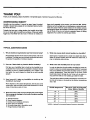
6. What Is the safe humidity level for my home?
In ordertodeterminethe safe relativehumidityfor homesex-
posedtovadouslowoutsidetemperatures,NESCA*conducted
tests and publishedrecommendedhumiditylevelsfor various
outdoortemperatures.These are shownin the chart.These
levelshelppreventdamageto yourhome suchas water run-
ningdownthewallsor evenbuildingup insidethewalls.
The safe indoor relative humidity percentage isnota fixed num-
ber but will increase or decrease as the outdoor temperatures
dse or fall.
Outside Temperatures Maximum Safe Recommended
Indoor Relative Humidity
-10 ° F 20%
0o F 25%
10° F 30%
20° F 35%
30 ° F 35%
"NESCA = National Environmental Systems Contractors Association,
3

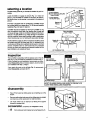
selecting a location
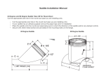
Consider these points as you choose the location for your hu-
midifier.
Locate humidifieron supplyair plenum(Fig. 1) or return air
plenum.Ifthe humidifieris installedonthe returnair plenum,
theflexiblehose,roundopening,isconnectedtothe supplyair
plenum.
If furnaceisequippedwithair conditioning,humidifiershould
be mountedaboveorat slopesideof"A"coiltoavoidpossible
splashing(Fig. 2) ofwaterin reservoir.
Humidifier should be installed so that if the humidifier or any
other connections should leak, the resulting flow of water will
notcause damage. Under no condition isSears and the manu-
facturer to be held liable for any water damage in connection
withthis humidifier.Never install humidifierin atticor crawl space
where freezing may occur or leaking will cause water damage.
if holes between supply air plenum and return air plenum must
be located more than 36 inches apart (Fig. 1), standard 6 inch
round pipe and fittings (not supplied) may be used, or an 8 foot
section of flexible tube No. 281152-05 may be purchased
through the Soars parts department. Materials needed for this
type installation are available at Sears.
11inchminimum
36 inchmaximum usingflex
hoseprovided*
• Purchaseaddttlc_laJ
hosefor greaterspans,
Plenum
_otachrmto
Return Air
Plenum
PlaceHumidifier
Duct
SupplyAi
Plenum
AirConditionerCoil
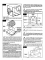
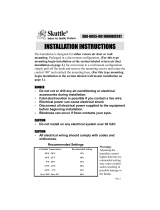
inspection
EE;I[t_€!
This humidifier is assembled with the bypass duct on the left
side (Fig. 3).This issuitable for installation as shown in Fig. 1.
If this is suitable for your installation, remove parts as shown
under Disassembly. Skip conversion steps A, B, and C. Start
your installation with Step 1, Page 5.
Ifyourequirethe motoron the leftside(Fig.4), removeparts
underDisassembly,andstartwith=A:'
AS SHIPPED
(lefthandflange)
Motor Side
By-PassFlange
ASCONVERTED
(righthand flange)
By-Pass Flange
;i
Motor Side
SAFETY GLASSES SHOULD BE WORN TO PREVENT EYE
INJURY WHEN INSTALLING HUMIDIFIER.
disassembly
la[C_l.'3
• Take off front panel by sliding panel up and pulling out at the
bottom.
• Remove media wheel and reservoir by slidingreservoir straight
out toward you while raising latch on right hand side.
• Lift media wheel out of reservoir by flexing wire support
outward to release shaft.
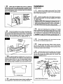
conversion (ifrequired, see "Inspection" above)
[] A From inside pull motorbracket up by top flange (Fig. 5).
TopFlangeof
MotorBracket
(PullUp to
Remove)
4

lltqm
!
Electric Disconnect
[] B Install motor bracket on left side. Make sure bracket is
firmly seated(Fig. 6).
Media
Wheel
k._ SmallDiameter
Wire Support.
Large_ PositionMedia
Diameter WheelShaft
Wire UnderDimples
Support ByFlexing
Outward.
[] C Removemediawheel wire supportsfromreservoir.In-
sertlargediameterwiresupportonleft sideofreservoirandsmall
diameterwiresupportonrightsideofreservoir.Placemediawheel
inwire supportswithgear onleftside ofreservoir.(Flexwire sup-
portoutwardtocapturemediawheelshaftunderdimples.)Fig.7.
Unit is now converted to a left side motor.
installation (onsheet metal plenum duct)
NOTE: Figures 8 & 9 show humidifier installation on supply air
plenum for illustration purposes only. If more convienient,
humidifiermay be mounted on return air plenum. Ifhumidifier is
installedon the return air plenum, the flexible hose (round collar
opening) is connected to the supply air plenum.
FIBER PLENUM DUCTS
NOTE: The mounting screws supplied are for standard installa-
tionon _ plenumducts.Ifyou have fiber plenumducts,
installthe humidifierand components with thru-bolts,nuts, and
washers (not supplied). If necessary, reinforce the humidifier
mountingarea onfiber ducts withsheet metal and provide addi-
tional bracing as required to supportthe weight ofthe humidifier
and water. (This fiber duct installation hardware is not supplied
and must be pumhased from your local hardware store.)
[] 1Mark a levellineon plenum.Holdstiffeneragainst theple-
numwithbottomedgeonlevellineandflangestowardyou.Mark
the locationof ell holes Includinglarge rectangularopeningin
centeron plenum(Fig.8).
[] 2 Drillor puncha largeholein one cornerof rectangle.
Thiswillallowyoutoinsertthetin snipsor metalsaw.
CAUTION: BE SURE NOTTO DRILL OR CUT INTO AIR
CONDITIONING COIL OR TUBING.
Drill(5)
118"Holes_
Cut Along
This Line
Mounting
Tabs
"
<-- - Stiffener
Cut Out
This Area - Level
Line
Hole"A"-- ,_•
I Furnace
Supply
Air
Plenum
[]
Cut out the area inside the rectangle. If any ofthe edges
are rough, file them smooth.
A
[]
HI" Drill the remaining holes marked on the plenum with a
1/8" drill bit.
[] 5 Mountthe stiffenerwith theflangestowardyou using
the four cornermountingholes.Do not useHole"A". Make sure
stiffenerisflush withtheplenum.Seal aroundedgewithcaulking
if necessary(Fig.8).
[]
U Hang the humidifier case on the mounting tabs. The
tabs may have to be bent out slightly to mount the case. Secure
the case to the stiffener with a sheet metal screw in hole "A".
I NOTE: It is very important that the case is secured. If the I
case isnot attached with the screw, itcould be dropped and
I
damaged during routine maintenance.
[] 7 Position collar at selected location. Mark center open-
ing and (5) holes. Cut out center opening and drill(5) 1/8" holes.
ReturnAir
Plenum
Collar
Location
Hot Air
Plenum
Furnace

[] 8 Attachcollarand flexiblehoseto plenum.Ifadditional
flexiblehoseisrequired,an eightfoot lengthisavailablethrough
thepartsdepartment,order281152-05. Beforetightening screws,
insertdamperbetweencollarand plenum(Fig. 10). Itshouldbe
openfor humidifieroperation.
Damper Blade
beSlideshut
fore using air
conditioning.
Slide open at
start of heating
season.)
9 Connect the flexible hose as shown using clamp pro-
vided. Do not allow flexible tube to come within 3" of furnace flue
pipe because of flue pipes extreme heat. If hose is under stress
(pulling), it may be necessary to drill 2 holes in humidifier collar
for screws. This will prevent clamp from slipping off (Fig. 11).
Screws(2)
InCollar
[] 10 It Is best to install an overflow line. Local codes may
require overflow protection. The overflow is in the bottom of the
humidifier reservoir (Fig. 12). Use 1/2" inside diameter rubber or
plastic tubing to connect to nearby floor drain. (Tubing not sup-
plied. Overflow tubing is available at your local hardware store.)
_ Overflow Drai_
[] 11 Installmedia wheel and reservoir trayin humidifiercase
and engage latch on right hand side to valve body inlet stem.
installation
WATER SUPPLY
[] 1 Water for the humidifier must be taken from a nearby
cold water line. Turn off the water supply. Drain by opening a fau-
cet at a lower level of the line.
[] 2 Position the saddle valve on the water line as close to
the humidifier as possible.You have been supplied with 10 feet of
1/4" plastic tubing.
SPECIAL NOTE: When measuring the distance from the
saddle valve location to the humidifier, keep in mind that the
tubingmust be supported;therefore, it must runalong ceiling J
J and walls. Measure along the path the tubing will follow. I
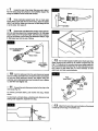
[] 3 Back out the piercing pin by turning the _ handle
counter clockwise and then clamp the saddle valve body securely
on the water line with rubber gasket positioned as shown (Fig.
13). On galvanized or copper pipe over 5/8", first ddll a 5/32' hole.
[ CAUTION: Forsafety,use a hand drillor groundedelectricdrill. ,J
[] 4 Turnhandleclockwiseuntil it has piercedthe water
lineandvalveiscompletely closed(Fig. 13).
[] 5 Partially uncoil the tubing. Slide the brass compres-
sion nut over the tubing. The threads in the nut must face the
tubing end. Place the brass compression sleeve as shown in Fig.
13. Slip brass insert intoend of tubing.
[] 6 Insert the tubing end into the saddle valve at threaded
stem "A" (Fig. 13) as far as it will go.Thraad the brass compres-
sion nut onto the valve, then tighten gently with a wrench. Take
care not to overtighten the nut.
BrassCompressionSleeve
=::O/ BrassInsert
Brass
Compression Nut
MOUNTING SADDLE VALVE
Water Pipe
UAU
Rubber Gasket
(Stem Up)
6

[] 7 Unwind the rest of the tubing. Take care not to kink it.
Run the tubing along flat surfaces to the humidifier. Support the
tubing as needed to avoid contact with furnace.
II[l_lill
[] 8 Close previously opened faucet. Turn on main water
supply. Place a pall under the and of the tubing. Open the caddie
valve, Flush the line. Make sure there are no leaks along the line
or at the valve. Turn valve off.
[] 9 Removethe quickdisconnectsocket,brasscompres-
sionnut,andbrasssleevefromhardwarebag(Rg. 14).Withwater
supplytubingcutto the properlength,slidethebrass compres-
sionnutandsleeveoverthetubingas describedinStep 5, Page
6. Slipbrass insertintothe endoftubing.
F
-I Sleeve
L _Humiditier
QUICK DISCONNECT
ASSEMBLY
Nut
Sleeve
Insert
Quick Disconnect
Socket
1/4" Plastic
Water Supply
Tubing
[] 10 Insertthetubingend intothe quick disconnectsocket
as far asitwillgoand holditthere,threadthebrasscompression
nut onto the quickdisconnectsocket, then tighten using two
wrenches,onetoholdquick disconnectsocketandonetotighten
nut.DO NOT over tighten nut.
[] 11 Connectthequickdisconnectsockettotheplugonthe
valvebody(Fig. 16).
To connect, pull back sleeve, pushsocket onto plug, release
sleeve.
To disconnect,pullbacksleeve,unlockingquickdisconnectand
sealingwater supplyline,separatefrom plug.
[] 12 Turnonwatersupplyatsaddlavalva.Chackwaterlevel.
Water shouldbe 3/8" belowtop of overflowcompartmentwall
(Fig.17).Ifadjustmentisnecessary,disconnectwatersupplytub-
ing,andremovefloat assembly(Fig.18). See instructionsonbot-
tom of float.To raisewater level,turn float clockwise.To lower
waterlevel,turnfloatcounterclockwise.
Float
Valve Button
Valve
Body
Float Pin
LI1[t]! i1,1
Disconnect
Plug
[] 13 Attach front panel. Be sure lipat bottom of front panel
is inside lip at front edge of humidifier case.

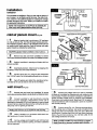
installation
HUMIDISTAT
The humidistatis designedto _ount on the coldair plenumof
yourfurnaceor onan interiorwallofthe home.The coldair ple-
num,howeveris thepreferredlocationfor sensingthe average
humiditythroughoutyourhome. Selectyourlocation and follow
theappropriateinstructions.
I OTE:THE HUMIDISTATAS SUPPLIED IS ASSEMBLEDFOR COLD AIR PLENUM INSTALLATION(FIG. 20).
cold air plenum mount (no.20)
[] 1 Select a locationthat isa minimumof 6" upstream
on coldair plenum (Fig. 19). Peel off paper backing and posi-
tion template supplied,drill four 1/8" diameter holes and cut
out center portionalong solid line. Peel off backing and apply
gasketmatedalas indicatedbydashedlines.
I CAUTION: DONOT install humidistat on hot air plenum. I
[] 2 Remove knob and cover from humidistat. To remove
cover, place screwdriver blade in slotat side of humidistat and twist.
[] 3 Position humidistat in opening and fasten with four
screws provided.
[] 4 Installshaftextension.Installcoverbysnappingonto
backplate. Press knobontoshaft extension.
5 Connect wiring (Fig. 21)_ Plug 24 VAC transformer
into 120 VAC outlet. Do not use existing transformer on furnace.
6 Peel off backing and attach the operating instruc-
tion label to the cold air plenum next to the humidistat.
wall mount (Fig.22)
On ColdAir
Plenum
HotAir
Plenum
6"
Minimum
I I
t
_,Air Flow I
"" _ -- "" _ Fumaca
Apply Gasket Here Around Opening
,Return Air
Plenum
Opening
Knob
DUCT MOUNT
Humid
Electdcal
Disconnect
Humidifier
t
120 VAC Wall Outlet
[] 1 Remove knobend coverfrom humidistat.To remove
cover,placescrewdriverbladeinslotatsideofhumidistatandtwist.
2 Convert humidistat for wall mounting by removing
control unit from backplate. Reassemble control unit to
backplate as illustrated in Pig. 22 with spacers to rear and shaft
forward. Remove electrical disconnect by cutting the (2) wires.
Strip ends 1/2" for splicing to wall wire.
I NOTE: Shaft extension is not required forwall mounting, I
3 Select a location on a convenient inside wall, usu-
ally beside your furnace thermostat.
[] 4 Run low voltage wire through the wall, Exit hole must
be within the lower backplate opening. (Purchase additional
wire as required.)
[] 5 Connect low voltage wires from wall to previously
cut leads on humidistat by stripping ends and using wire nuts
(not provided). Position and fasten humidistat to wall with four
screws provided. Install cover by snapping onto backplate.
Press knob onto humidistat shaft. Make sure 1/8" air space is
maintained between wall and backplate to allow air circulation
and humidity sensing.
6 Connect wiring (Fig. 21). Remove electrical discon-
nect by cutting wires on harness, strip ends and splice to low
voltage wire from wall humidistat using wire nuts. (Wire nuts
not provided. Purchase them from your local Sears Hardware
Store.) Plug 24 VAC transformer into 120 VAC outlet. Do not
use existing transformer on furnace.
I NOTE: Humidifierhumidifiesonly when fumaco ison, however,
Media _ willtum wheneverhumidistatcallsforhumidity. J
8

Mounting,
Screws
(4)
Hole In Wall
Mounting
Screws
Wall Mount
I-<--Spacers
Control
Unit
NOTE: Byturning knob to the test position humidifier should
start. (Do not leave on test.) Ifthe installation is being made in
the summer or when the humidity is high, turn knob to the test
position and the humidifier should start. When your system is
working satisfactorily, turn knob back to the minimum humidity
setting until winter.
operation
1 Set knob to the lowest temperature predicted for a
24-hour period. Because of differences in house construction
you may want to try a higher or lower setting to achieve proper
humidity.
2 Change knob settings as outdoor temperature changes
Occur.
J WARNING:
DO NOT LEAVE KNOB SET ABOVE "+20" OR HUMIDI-
FIER WILL RUN CONSTANTLY AND MAY OVER HU-
MIDIFYYOUR HOME.
AIR CONDITIONING - IMPORTANT:
If your furnace has air conditioning (cooling), close the damper
completely during summer months and turn the humidistat to
the Minimum Humidity setting. BE SURE TO OPEN DAMPER
DURING HEATING SEASON.
CAUTION:
Do not use tablets in an attempt to control lime de-
posits in this humidifie!! Use of tablets may cause
humidifier to splash causing damage to humidifier
or furnace.
maintenance
CLEANING AND SERVICE INSTRUCTIONS:
This humidifier is an appliance which works with water. The
dissolved minerals normally found in tap water are left as lime
deposits in the humidifier. REGULAR CLEANING is necessary
to keep the parts free of lime deposits. Deposit build-up will
reduce humidifier output. Ease of servicing has been foremost
in the design of this humidifier. Service at least every (4) four
weeks during the heating season or more often depend-
ing on the water conditions.
1.
2.
3,
4,
5.
6.
7.
8.
IF SWEATING OF WINDOWS OR WALLS
OCCURS OR IF AIR ISTOO DRY:
Check dial setting, Indicator should point to the lowest 24-hour
temperature, If setting does not agree, readjust knob to proper
number and wait 24-hours for sweating to stop, If dial setting 9,
was correct and conditions have not changed, rotate knob back
and forth from TEST to MINIMUM HUMIDITY SETTING. If hu-
midifier goes ON and OFF, control is operating properly. 10.
SPLASH INSIDE HUMIDIFIER:
This humidifier depends on the difference of airpressure between
the supply air plenum and the return air plenum to propel air
through the humidifier. Some furnaces have higher pressures than
others. This could result in air travelling at high speed through
the humidifier.This can cause droplets of water to be picked up
and splashed against the inside of the humidifier case. Eventu-
ally a coating of lime will build up. It could in extreme cases, cause
leaking of water from the humidifier. If possible, operate the fur-
nace blower at a lower speed.
TO REDUCE SPLASH:
9
Partially close the damper located in the collar on the
return air plenum. Some experimenting may be necessary to
find the proper setting.
11.
Turn humidistat to minimum humidity setting.
Disconnect water supply at the humidifier using the quick dis-
connect. The water is automatically shut off.
Remove the front panel of the humidifier, remove drain line (if
used) and slide out reservoir and media wheel while raising
latch on right hand side.
Lift out the media wheel by flexing wire support outward to
release shaft.
Pull out stainless steel pivot pin and remove float and float
arm.
Pour contents of reservoir down the drain.
Lift out the reservoir liner and replace, (Part No.215711-01),
or clean.
Clean lime from all parts using a solution of vinegar and wa-
ter, detergent and water, or Sears All-Purpose Humidifier
Cleaner (Stock No. 42-14713).
Remove media pad from inside ofwheel and clean thoroughly,
replace if necessary (Sears Stock No.42-9335). IMPORTANT:
Stretch media lengthwise before placing in wheel
Ifthe Reservoir has been overflowing, the Float Valve Button
may be worn. In normal operation this button will erode even-
tually much like a faucet washer. Remove the Float Valve
Button, turn it over and reinsert or replace after both surfaces
are worn (Fig. 23). Replacement buttons are available at
Sears.
Reassemble unit (flex wire support outward to capture media
wheel shaft under dimples), connect water supply and drain
line (if used), and turn humidistat to desired setting. Unit is
back in operation.
NOTE: Make sure latch on right hand side is engaged to
float valve body inlet stem. This prevents reservoir move-
ment and possible disengagement of media wheel gears
during operation.

Body
Pin
*Reveme buttonif it
hasnotbeen used.
Replacewithnew
buttonifbothsides
are worn.
SUMMER SHUT DOWN:
Unplugtransformer,close saddlevalve, closebypassdamper.
CLEAN PER ABOVE AND LEAVE RESERVOIR EMPTY. (Asa
reminder,you may wantto puta tag or stickeron the unitindi-
cating it has been shut downfor the summer and will require
start up inthe fall.)
FALL START UP:
Plugin transformer,open saddle valve, open bypass damper
and sat humidistatto TEST position.Check for properwater
level and media wheel operation. Set humidistataccordingto
outdoortemperatureas instructedon label.
SERVICING THE FLOAT
If the humidifier has been overflowing, the float valve button
may be worn. This button will wear much like a faucet washer.
To service:
1. Disengage quick disconnect.
2. Remove float from humidifier (pull out pivot pin).
3. Service float as shown in illustration at left.
4. Reinstall and test float.
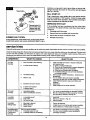
service hints
Frequently what seems to be a major problem can be solved very easily. Listed below are the common concerns with any humidifier.
Check the simple things first. Remove the front panel and see if there is a crusty, white lime build-up on the media pad. The lime build-
up won't hurt the humidifier, but will reduce its output. Low output might just mean your humidifier needs cleaning. While you're
chocking for lime build-up, look to see if the media wheel is turning. If not, check the power supply.
CONDITION WHAT TO CHECK WHAT TO DO
1. Does humidifierneed cleaning.
2. Ismediawheel rotating?
3. Hun_idistatsetting.
4. Water tounit.
Too little
Humidity
Too much
Humidity
Humidifier 1. Is humidifier level?
Overflows 2. Float valve.
3. Air flow too high.
Humidifier 1. Mounting or plenum.
Making Noise 2. Water pressure.
3. Media Wheel.
5. Excessive air loss in house.
6. Is water level correct?
7. Is damper open?
1. Humidistat setting.
2. Other humidification sources.
This is a normal condition
1. If heating season is over.
2. If heating season isjust starting.
HumidifierMotor
Comes OnWhen
Furnace Isn't
Running
1. Clean humidifier and clean or replace media pad
and reservoir liner.
2. a. Clean or replace media pad.
b. Check to see if transformer is properly plugged in.
c. Inspect main fuse or circuit breaker.
d. Check to see if media motor is rotating.
e. Humidistat setting too low, turn knob clockwise
to increase humidity.
3. Set for proper outdoor temperature - lowest 24-hour
temperature.
4. Turn on saddle valve and check for possible
obstruction in water line. Is water supply connected?
5. Close fireplace damper, seal around doors and
windows.
6. Adjust float.
7. Slide damper out for winter operation.
1. Turn knob counterclockwise to decrease humidity.
2. May be a temporary condition caused by moisture
from laundering, bathing, cooking, etc.
1. Level unit.
2. Service as shown in Fig. 23.
3. Adjust damper.
1. Tighten all fasteners.
2. A slight sound is normal as water enters humidifier.
3. Check clearance of media wheel in reservoir.
1. Turn knob on humidistat to minimum setting.
2. This is a normal condition since humidistat is
controlling humidifier.
10

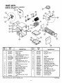
repair parts
KENMORE "2500" CENTRAL HUMIDIFIER
MODEL NO. 303.936613
\
I
/
/
KEY PART KEY PART
NO. NO. DESCRIPTION NO, NO. DESCRIPTION
1 21571501
2 35586401
3 05301101
4 21571601
5 STD575026
6 STD575025
7 35561801
8 21582703
9 43148901
10 43149102
11 21581001
12 21571101
13 21571901
14 21570901
15 21575001
16 35577002
17 03022815
18 35561102
19 42063901
THIS IS A PARTS LIST, NOT
Plenum Stiffener
Upper Case
Lower Case
(Includes Key Nos. 33 & 34)
Motor and Bracket
Brass Compression Sleeve 1/4"
Brass Compression Nut 1/4"
Saddle Valve
(Includes Key Nos. 5 & 6)
Plastic Supply Tubing (1/4" x 10')
Damper
Collar and Flexible Tube (3")
Tube Clamp
Reservoir (Water Tray) Liner
Support Bracket (Gear)
Media Wheel with Gear
Media Clip (3 Req.)
Media Pad (42-9335)
Slinger Washer
Float Valve
(Includes Key Nos. 19-24)
Float
A PACKING LIST.
20 22513801
21 28110101
22 28110201
23 21569101
24 03029401
25 21572601
26 21571001
27 21571202
28 21572701
29 21586101
30 03022701
31 STD610603
32 41067501
33 05299101
34 05299201
STD610803
21584001
35587301
35575901
21596001
Float Arm
Float Valve Button
Pivot Pin
Valve Body
Locknut
Support Bracket (Shaft)
Reservoir (Water Tray)
Front Panel
Plug Quick Disconnect
Socket/Quick Disconnect
U Type Speed Nut (4 Req.)
Type B Screw (#6 x 3/8") (4 Req.)
Brass Insert (2 Req.)
Push Rivet
Latch, Reservoir Lock
Screw (#8 x 3/8") (10 Req.)
Low Voltage Wire (10 ft.)
Humidistat (24V)
Transformer (24V)
Owners Manual
*Not Shown
11

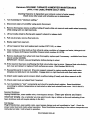
Kenmore 303.93661 FURNACE HUMIDIFIER MAINTENANCE
(APPLY THIS LABEL WHERE EASILY SEEN)
Cleaning frequency is dependent upon mineral content of water supply.
Check every other week until schedule can be determined.
1. Turn humidistat to "minimum setting."
2. Disconnect water at humidifier using quick disconnect.
3. Remove front panel, remove overflow tubing (if used), slide out reservoir and media wheel assembly
while raising latch on right hand side.
4. Lift out media wheel by flexing wire support outward to release shaft.
5. Pull out pivot pin, remove float and arm.
6. Empty water from reservoir.
7. Lift out reservoir liner and replace (part number 215711-01), or clean.
8. Clean residue and lime build-up from all parts using a solution of vinegar and water, detergent and
water, or Sears All-Purpose Humidifier Cleaner (stock number 42-14713).
9. Remove media pad from wheel and clean thoroughly; replace pad if necessary - available from Sears
(stock number 42-9335).
IMPORTANT: Stretch new pad lengthwise before placing in wheel.
10. If the reservoir has been overflowing the float valve button may be worn. Remove float valve button,
turn over and reinsert or replace if both surfaces are worn. (Part Number 281101-01)
11. Reassemble parts in reservoir (Flex wire support outward to capture media wheel shaft under
dimples) and slide back into humidifier. Engage latch on right hand side with float valve stem.
12. Attach water supply quick connect, attach overflow tubing (if used), and allow reservoir to fill.
13. Check water level and adjust float if required.
14. Turn humidistat to "test" momentarily and check for media wheel rotation. Reset humidistat
according to outdoor temperature as instructed on label and reinstall front cover. Unit is back in
operation.
Summer Shutdown
Unplug transformer, close saddle valve, close bypass damper. Clean per above and leave
reservoir empty. (Asa reminder you may want to put a tag or sticker on the unit indicating it has
been shutdown and will require startup in the fall.)
Fall Startup
Plug in transformer, open saddle valve, open bypass damper and set humidistat to "test". Check for
proper water level and media wheel operation. Reset humidistat according to the outdoor temperature as
instructed on label. Unit is back in operation.
PIN 21604001R10-00

Kenmore 2500
15 GALLON
CENTRAL HUMIDIFIER
For the repair or replacement parts you need
Call 7:00 a.m. - 7:00 p.m., 7 days a week
1-800-366-PART
(1-800-366-7278)
@
For in-home major brand repair service
Call 24-hours a day, 7 days a week
1-800-4-REPAIR
(1-800-473-7247)
For the location of a
Sears Repair Service Center in your area
Call 24-hours a day, 7 days a week
1-800-488-1222
For information on purchasing a Sears
Maintenance Agreement or to inquire
about an existing Agreement
Call 9:00 a.m. - 5:00 p.m., Monday-Saturday
1-800-827-6655
SEARS
r;/,'/,,IR_,/_/_ri/_
America's Repair Specialists
Tell Sears You Want It Installed,
Then Relax...
When Sears arranges the installation, you can be sure the job is
cloneright.We willarrange for professional workmanship...and
we'll take care of the entire project.What's more, during installa-
tion you get insured protection...against property damage and
also against accidents to workmen. All you have to do istalk to
your Sears salesperson or call 1-800-4MY HOME (1-800-469-4663)
or your nearest Sears store today for detailed information.
Sears, Roebuck and Co., Hoffman Estates, IL 60179 U.S.A.
10-00 215960-01-06 Printed in U.S.A.
-
 1
1
-
 2
2
-
 3
3
-
 4
4
-
 5
5
-
 6
6
-
 7
7
-
 8
8
-
 9
9
-
 10
10
-
 11
11
-
 12
12
-
 13
13


Ask a question and I''ll find the answer in the document
Finding information in a document is now easier with AI
Related papers
Other documents
-
Crystorama 501-GA Operating instructions
-
American Standard THUMD500A User manual
-
FIELD CONTROLS FM-90 EVENMIST Humidifier Owner's manual
-
 Speedi-Products SM-SDL45 08 Operating instructions
-
 Skuttle Indoor Air Quality Products SK0-0055-001 User manual
-
Aprilaire Dehumidifier 4655 User manual
-
Air King 5000 Installation guide
-
Bryant HUM-56-1 User manual
-
EASTMAN 04182LF Operating instructions
-
Gibraltar Building Products SS414G Operating instructions

