Page is loading ...

Kenmore 2700
17 GALLON
CENTRAL HUMIDIFIER
Installation
Maintenance
Repair Parts
Troubleshooting
Sears, Roebuck and Co., Hoffman Estates, IL 60179 U.S.A.

contents
WARRANTY ........................................... 2
BEFORE YOU START
Rules for Safe Installation
and Operation ................................... 2
Tools and Materials Needed .............. 2
UNDERSTANDING HUMIDITY .............. 3
SELECTINGA LOCATION .................... 4
INSTALLATION...................................... 4
DISASSEMBLY...................................... 4
WATER SUPPLY................................... 6
HUMIDISTAT.......................................... 7
OPERATION .......................................... 8
MAINTENANCE ..................................... 9
SERVICE HINTS .................................. 10
REPAIR PARTS .................................... 11
introduction
Please readthe instructionsbeforeyou installand useyourhumidifier.Thiswillhelpyou obtainthe fullvaluefromthehumidifier.Itwill
also helpyou avoidanyneedlessservicecost,ifthe problemissomethingwe cannotcontroland cannotcoverinourWarranty.
FULL ONE YEAR WARRANTY ON HUMIDIFIER
If, within one year from the date of pumhaee, this humidifier fails due to a defect in material or workmanship, Seers will
repair it,free of charge.
WARRANTY SERVICE IS AVAILABLE BY SIMPLY CONTACTING THE NEAREST SEARS STORE OR SERVICE
CENTER INTHE UNITED STATES.
This warranty gives you specific legal rights,and you may also have other rights which vary from state to state.
This warranty DOES NOT cover the replacement media pad.
Sears, Roebuck and Co., Dept. 817WA, Hoffman Estates, IL 60179
DO-IT-YOURSELF CHECK LIST
Ifyoufeelthefollowingoperationsarewithinyourskills,youshould
haveno difficultyinstallingthis humidifier.
[] Cuttingand drillingsheet metal.
[] Usinghandtools:screwdriver,wrench,etc.
[] Rookingup lowvoltage electricalconnections.
SEARS INSTALLATION POLICY
AllinstallationlaborarrangedbySearswillbeperformedina neat,
workmanlikemannerinaccordancewithgenerallyacceptedtrade
practices.Further,all installationswillcomplywithall locallaws,
codes, regulations,and ordinances.The customerwillalso be
protected,duringinstallation,by insurancerelatingto property
damage,Work]nan'sCompensation,andpublicliability.
Youmustrealizethatthewrong useof any toolcanbe danger-
ous. Be sure you knowhowto use the toolsand equipmentto
avoidany possiblehazards.If you haveany doubtwe ask that
youcontactyourSearssalesperson.They willarrangefor profes-
sionalinstallation.
SEARS INSTALLATION WARRANTY
In additionto anywarrantyextendedto you on the Sears mar-
chandiseinvolved,whichwarrantybecomes effectivethe date
themerchandiseisinstalled,shouldtheworlonanshipofanySears
arrangedinstallationprovefaultywithinoneyear,Searswill,upon
noticefrom you, cause suchfaults to be correctedat no addi-
tionalcostto you.
before you start
RULES FOR SAFE INSTALLATION & OPERATION
1. Read theserulesandtheinstructionscarefully.Failuretofol-
lowthe rulesand instructionscouldcausebodilyinjuryand/
or propertydamage.
2. Check your local buildingcodes and utilitystandards.The
installationmustcomplywiththeirrules.
3. Alwaysshutoffthefurnaceblowerbeforeinstallingorservic-
ingthe humidifier.
4. Alwayswearsafety glasseswhen installingor servicing.
5. HUMIDIFIER MUST NOT BE INSTALLEDINAREAWHERE
FREEZING IS POSSIBLE OR LEAKING WOULD CAUSE
WATER DAMAGE.
6. Followa regularservice and maintenanceschedule.
7. Alwaysshutoffelectricityand watertothehumidifierbefore
servicing.
8. Whenthefurnacebloweris usedfor air-conditioning, thehu-
midifierdampershouldbeclosed,andthe humidistatshould
beturnedtothe minimumhumiditysetting.
g. NEVER OIL ANY PARTOFTHE HUMIDIFIER.
10. To preventoverhumidification,humidifiermust notbe oper-
ated above humidiatat high position or above the +20
position (whichever applies) except briefly to test op-
eration after installation or servicing.
TOOLS AND MATERIALS NEEDED
• SafetyGlasses
• Straightedge ruler
• Pencilor greasepencil
• Handdrillor grounded
electricdrill
• Drillbits,5/32",118"
• "r]nsnipsor metal
cuttingsaw
• Wire strippersor razorknife
• Screwdriver(flatpoint,and
Phillips,mediumsize)
• File
• Level
• Hammer
• Smelladjustablewrench
• Centerpunch
• Springhoseclamppliers

THANK YOU!
Thankyouforselectinga Sears Humidifier.Itwillprovideyearsofserviceif yougiveita littlecare.
UNDERSTANDING HUMIDITY
Humiditycan be puzzling. It cannot be seen, heard, touched,
smelledortasted. Many peopledo notunderstandwhata humidi-
fierwillorwillnotdo.
Probablythe bestway tojudge whetherthe humidityistoo high,
toolowor aboutrightisto watchyourwindows.Iftheyareheavily
fogged you mostlikelyhave too much.Ifthere is no moistureon
them at all, especiallyinthe corners,you have too little.(NOTE:
Moisturewillnotnormallyformon thermopaneor whenstormwin.
dowsare used.)ff there issome moisturein the windowcorners
andalongtheedges,thehumidityisjustaboutright.Thisisa good
role of thumb, it you do not have an expensivepiece of testing
equipment.Yourcomfortisanothergoodcheck.
TYPICAL QUESTIONS ASKED
1. Why do moisture requirements vary from home to home?
Requirementsdepend onthe amountanddrynessof airto be
humidified.The largerand morelooselyconstructedthe home,
the greaterthe quantityofmoisture required.
5. Whet else causes static shock besides low humidity?
Some typesofcarpetstend tocreate morestaticthan others.
While the properhumiditylevel willreducethe staticlevel, it
may noteliminatestaticentirely.
2. How can I best check my home's relative humidity?
Firstgive your humidifiertime to buildup the humidityto an
acceptablelevel.Instrumentsare availabletomeasurerelative
humidity,but from a practicalstandpoint,yourcomfortis the
bestguide.Youcannotdepend ontable top or wall hungdial
gauges.
3. How long will It take my humidifier to build up the
humidity In my home?
Muchdependsonthe outsidetemperature,timeofyear,home
construction,and howdriedoutthehomehasbecome.Insoma
cases,itmay take a week or mare.
4. What are some of the common things that cause higher
then average sir leakage In the home, therefore causing
low humidity?
A. Jalousiewindows
B. Open fireplacedampers
C. Cracksaroundwindows end doors
D. Open doorsendwindows
E. Unusuallylargeatticorfoundationvents
F. Rangehoodsand bathfans
6. What Is the safe humidity level for my home?
In ordertodeterminethe safe relativehumidityfor homesex-
posedtovariouslowoutsidetemperatures,NESCA*conducted
tests and publishedrecommendedhumiditylevelsfor various
outdoortemperatures.These are shownin the chart.These
levelshelppreventdamage to yourhomesuch as water run-
ningdownthewallsor evenbuildingupinsidethewalls.
The safeindoorrelativehumiditypementageisnota fixednum-
ber butwill increaseor decreaseas theoutdoortemperatures
riseorfall.
Outside Temperatures
-10° F
0° F
10° F
20° F
30° F
MaximumSafe Recommended
Indoor RelativeHumidity
20%
25%
30%
35%
35%
*NESCA- Ndonal EnvironmentalSystemsContractorsAuociation.
3

selecting a location
Consider these points as you choose the location for your
humidifier.
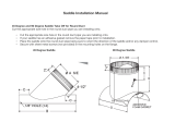
Locate humidifieron supplyair plenum(Fig. 1) or returnair ple-
num.Ifthehumidifierisinstalledonthe rstumairplenum,the flex-
iblehose,roundopening,isconnectedto the supplyair plenum.
If furnace is equipped with air conditioning, humidifier should be
mounted above or at slope side of "A" coil to avoid possible splash-
ing (Fig. 2) of water.
Humidifiershouldbe installedsothatifthehumidifieroranyother
connectionsshouldleak,the resulting flowofwaterwillnotcause
damage.Undernocondition isSearsandthe manufacturertobe
heldliablefor anywaterdamage in connection withthis humidi-
fier.Never installhumidifierinattic orcrawlspacewherefreezing
may occuror leaking will causewaterdamage.
If holesbetween supplyair plenum and return air plenum must
be locatedmore than 40 inchesapart (Fig. 1), standard6 inch
roundpipeand fittings(not supplied)may be used, or an 8 foot
sectionofflexibletube No. 28115205 maybe pumhasedthrough
the SearspartsdepartmenLMaterialsneededforthistypeinstal-
lationare availableat Seam.
installation
The humidifierisshippedwiththe block-offpanelon the
rightside(Fig.3).Thisissuitableforinstallationasshown
in Fig. 1, above. If this is suitablefor yourinstallation,
removepartsas shownunderDISASSEMBLY.
If you require the block-off panel on the left side (Fig. 4),
start with DISASSEMBLY then remove block-offpanet from
dghtflange and install with the same screws on leftflange.
FIBER PLENUM DUCTS
NOTE: The mountingscrewssuppliedere forstan-
dard installationon sh_t metalplenumducts.
If you have fiber plenum ducts, install the hu-
midifierand components withthru-belts,nuts,and
washers (not supplied).(This fiber duct installa-
tion hardware is not supplied and mustbe pur-
chased from you local hardware store.)
16 inch minimum
40 inch maximum using flex
hose provided*
• Purchaseadditional
hosefo_greaterspans.
ReturnAir
Plenum
PlaceHumidifier
SupplyAi
Plenum
Air ConditionerCoil
AS SHIPPED
LeftHandFlange
Block-Off
Panel
BypassFlange
Block-Off
Panel
Fumac_
Duct
AS CONVI=HTI=U
RightHandFlange
BypassFlange
CAUTION: Safetyglassesshouldbe wornto pre-
venteye injurywhen installinghumidifier.
disassembly
1.Takeofffrontpanel byslidingpanelup and pullingoutat
the bottom.
2. Removecorrugated spacer and by.peesbootwhich con-
talnsdamper,collar &flextubeandtubedamp.
3. Remove mediapad by liftingbottom edgeup slightlyand
pullingout.
Cese/umemUy

[] 1 Mark a level lineonthe supplyairplenum(Fig.6). [] 6 Drillthe fourholesmarkedon the plenumwitha 1/8"
drillbit.Holesmustbelocatedat end ofslot(Fig. 7).
4"Min.
J_
Level Line
1
Furnace
Sup,ply
Air
i Plenum
[] 2 Hold case assemblyagainstthe plenumwith bottom
edge ofrear openingon levelline.Markfourcomersofrectangu-
laropeningandfour screwlocationsonplenum,Screwholesmust
be locatedat end of slot(Fig, 7).
Locstions
Level
Line
I
Furnace
_l, SupplyAir
Plenum
1
[] 3 Connectcorner markstooutlinerectangularopening.
Centerpunchfour screwlocations(Fig.8).
[] 4 Drillor puncha largeholein one cornerofrectangle.
Thiswillallowyou to insertthetin snipsor metalsaw.
I
CAUTION: Be sure notto drillor cut intoair conditioning
coilortubing.
I
[] 7 Attachthe humidifiercase assembly on the plenum
using4 #8 screwsprovided.
Drill4
1/8"Holes
CutAlong--
ThisLine
_tcou[
ThisArea
• •
Furnace
Level
_ne
j Plenum
[] 8 Holdcollarandflexible tube assemblyagainstcoldair
plenumat desiredlocation.
[] 9 Mark roundopening insidecollar and five mounting
holes(Fig. 9).
[] 10 Centerpunchfivescrewlocations.Drillorpuncha large
holewithinthe roundopening.Cut outthe area insidethe round
opening.Drillthefive holes(Fig.9).
ColdAir
Plenum
HotAir
Plenum
Furnace
[] 5 Cutoutthearea insidethe rectangle.Ifanyoftheedges
arerough,filethem smooth(Fig. 8).
5

[] 11 Attachcollarand flexiblehosetocoldairplenumus-
ing(5)#8 screwsprovided.Ifaddifionaiflexiblehoseisrequiredan
eightfootlengthisavailablethroughthe partsdepartment,order
28115205.Beforeflghtening screwsinsertdamperbetweencollar
and plenum(Fig. 10). Itshouldbe openforhumidifieroperation.
___ amper Blade
(Slideshut
beforeusingair
conditioning.
Slideopenat
startof heating
season.)
[] 12 Attach bootto humidifierusing (2) #8 screwsen-
gagedinthe tinnermannutsprovidedinbypassflange.Connect
the flexibletube as shown usingclamp provided.Do not allow
flexibletubetocome within3" offurnace fluepipebecauseofflue
pipe'sextremeheat (Fig. 11).
(5) #8 Screws #8 Screw
/
#8 : Clamp
[] 13 The waste waterdrainmustbe installed.The drain
isinthe bottomofthe humidifierreservoir(Fig.12).Use 1/2" I. D.
x 10"plasflc tubing to connect drain.(Tubingissupplied.)Addi-
tionaltubing isavailableat yourSears store,Stock No. 42-3433
II
I
Ill
='q_-- Spring
°%%
L.> HoseTo
Drain
I CAUTION: Wear safetyglasses.
I
[] 14 Uaingspringhoeaclamppliem,expandhoeaclamp
andslide overen_lof_ tubingapproximately2 inches.Slide
plastictubing ontowaste water dr_n. Expandhoseclamp and
poaiUontoclamp tubingto waste waterdrain(Fig. 12).
installation
WATER SUPPLY
I CAUTION: Use plastic tubing supplied, Do not use copper
tubing because it may become disconnected when used with
hardware supplied.
[] 1 Waterforthe humidifiermustbetakenfroma nearby
coldwaterline.Turnoffthewatersupply.Drainbyopeninga fau-
cet at a lowerlevelofthe line.
[] 2 Mountthesaddlevalveonthewaterlineas closeto
the humidifieras possible.Youhavebean suppliedwith(10) feet
of 114"plastictubing.
SPECIAL NOTE: When measuring the distancefromthe
saddlevalvelocationtothehumidifier,keepinmindthatthe
tubing mustbesupported;therefore,itmustrunalongceiling
and walls.Measurealongthe paththe tubingwillfollow.
[] 3 _ out thepiercingpin bytumingthe "T" handle
counterdockwiseand thenclampthe saddlevalvebodysecurely
onthe waterlinewith rubber gasketposifionedasshown(Fig.13).
Ongalvanizedor copper pipeover5/8", firstdrilla 5/32" hole.
I AUTION: Forsafety usea handdrillor groundedelectric
drill.
[] 4 Turnhandleclockwiseuntilit haspiercedthe water
lineandvalve iscompletely closed(Fig. 13).
[] 5 Partiallyuncoilthetubing. Slidethebrasscompres-
sion nut over the tubing. The threadsin the nut mustface the
tubing end. Placethe brasscompressionsleeveas shown(Fig.
13). Slipbrassinsertintoend oftubing.
[] 6 Insert the tubing end into the saddle valve at
threaded stem"A"(Fig. 13) as far as it willgo.Threadthe brass
compression nutontothevalve,thentightengentlywith a wrench.
Takecare notto overtightenthe nut.
BrassCompressionSleeve
f BrassInsert
Brass
CompressionNut
MOUNTING SADDLEVALVE
6

[] 7 Unwind the rest of the tubing. Take care not to Idnk
it. Run the tubing along flat surfaces to the humidifier.Support the
tubing as needed to avoid contact with furnace.
[] 8 Closepreviouslyopenedfaucet.Turnon mainwa-
ter supply.Place a pail under the end ofthe tubing.Open the
saddlevalve. Flushthe line.Make sure thereare noleaksalong
the lineor at thevalve.Turnvalveoff.
[] 9 Withwater supplytubingcuttothe properlength,
slidetheplasticcompressionnutoverthetubing.Slipbrassinsert
intotheend oftubing.
Check ForLeaks,
Tightenif Necessary._ PlasticTubing
BrassInsert
Valve
Compi'ession
Nut
[] 10 Insertthe tubingend intothe solenoidvalve fitting
asfar as ifwillgoand holditthere,threadtheplasticcompression
nutontothefitting, thentightensecurely,finger tight(nowrench).
Do notovertightennut(Fig. 14).
[] 11 Turnonwatersupplyatsaddlevalve.Checkforleaks
at solenoid valve fitting and plastic compression nut.
I
NOTE: waterwillnotflowthru humidifieruntilelectricalin- I
stallationiscompleted.
I
installation
HUMIDISTAT
The humidiatatisdesignedto mountonthe returnair plenumof
yourfurnace or on an interiorwall ofthe home.The return air
plenum,however,isthe preferredlocationfor sensingthe ever-
age humiditythroughoutyourhome and isthe locationcovered
byinstallationsteps 1through11.(ifyoudecideonthewallmount
location,thehumidistatcontrolunitmustberemovedand mounted
tothe oppositeside of the plasticbackplateeo it willbe housed
l_aideoftheplasticcover- omitsllaft extana]on- purchaseaddi-
tional low voltage wire and run wire inside of wall to exit hole
withinthe loweropeningofthebackplate.)
NOTE: The humidistat as supplied is assembled for return
air plenum installation (Fig. 16.).
RETURN AIR PLENUM MOUNT
[] 1 LOCATETHE HUMIDISTATon returnair plenum
(Fig, 15). DO NOT install humidistat on supply air plenum.
HUMIDISTATMUST BE MOUNTED AT LEAST 6" UPSTREAM
FROM FLEXIBLE HOSE (OR HUMIDIFIER IF HUMIDIFIER
INSTALLEDON RETURN AIR PLENUM).
-- ._.. I _% /..i -- .1_. I
Humidistat Supply
On Return J,_,.l[... _,._ / Plenum
AirPlenum /I _ I-J'F--_-II
only/ IF
6" t I I
Minimum I A
I
I _ AirFlow J
_Fur"'nac_"
[] 2 HUMIDISTATMOUNTS INA HORIZONTALPOSI-
TION. Peel paperbackingfrom templateand paste it on return
airplenumwherehumidistatistobe mounted.Keep level.
[] 3 Drill118"holes for the four mounting screwsas
shownonthetemplate.
[] 4 cutoutcenterportionoftemplatewithinsolidlines.
[] 5 After removing paper backing from gasket, apply
gasket around return air plenum opening as indicated on tern-
plate (Fig. 16).
ApplyGasket HereAroundOpening
Backplate
Mounting Plenum
Screws
(4) Opening
_" ControlUnit
I Mounting
Screws(2)
LSheft Extension
7

WIRINGTOCONSTANT120VACUNE
EXTERNALTOFURNACE
Junction _
_U J Inllal SiI# _ddl In Rltum Air Plenum
IllI (_ _-._lly _ o=_s)
IIII Pu_ thisacce_lotyseparatelyifneeded.
IIII Av=_ _o_s_-s P,_,_ Ser_=
[] 6 Usinglowvoltagewiresupplied,connectspadeter- I
minalstosolenoidvalveon topofhumidifier. J NOTE: Wiringmustconformtolocalcodes.
I
[] 7 Position and support wire to humidistat location.
Separate wire. Cut only one wire, strip ends.
[] 8 Feed wires thru opening in humidistatback plate
and attachtoscrewterminals.Mounthumidistaton retumair ple-
numusing(4) #8 screwsprovided.Installshaftextension,cover
and knob(Fig. 16).
CONTROL CIRCUIT: Forproperoperationand waterconserve-
fion, thishumidifiermustbe wiredso itwilloperateonlywhen the
furnace bloweris runningand the humidistatcalls for additional
humidity.Two methodsare shown(Fig. 17 and Fig. 18):
Fig 17: WIRING INTO FURNACE - FOR ANY FORCED AIR
FURNACE WITH SINGLE SPEED 120 VAC BLOWERONLY.
CAUTION: Do notuse thismethodwith multi-speedblow-
em or blowemotherthan 120 VAC.
Rg 18: WIRING EXTERNALTO FURNACE- FORANYFORCED
AIRFURNACE INCLUDING FURNACEWITH OTHER THAN 120
VAC BLOWER MOTOR OR FURNACE WITH MULTI-SPEED
BLOWER MOTOR.
NOTE: Somefurnacesare equippedwith accessorytermi-
nalsthat can beusedfor thehumidifier.Inthis case,consult
thefumane manufacturer'srecommendationfor wiring.
[] 12 Attach"OperatingInstructionLaber toreturnair ple-
numnexttothe humidistat.Peeloffpaperbackingandsticklabel
indesiredlocation.
operation
[] 1 Set knobtothe lowesttemperaturepredictedfora
24 hourpe_nd. Becauseofdifferencesinhouseconstruction you
maywanttotrya higherorlowersettingtoachieveproperhumidity.
[] 2 Change knob settings as outdoor temperature
changesoccur.
[
WARNING: DO NOT LEAVEKNOBSET IN "TEST" POSI-
TION ABOVE %20" OR HUMIDIFIER WILL RUN CON-
STANTLY.
I
IF SWEATING OF WINDOWS OR WALLS OCCURS OR IF AIR
IS TOO DRY:
Check dial seffing. Indicatorshouldpoint tothe lowest24 hour
temperature.If settingdoes not agree, readjustknobto proper
i numberandwait24 hoursforsweatingtostop. Ifdialsettingwas
correctand conditions havenot changed, rotateknobbeckand
forthfromTEST toMINIMUM HUMIDITY SETTING. Ifhumidifier
goesON and OFF,control isoperatingproperly.
[] 9 Tum offelectricityat fusebox.Using(two)wire nuts
and conduit nutsupplied, install24 VAC transformerto 120 VAC
supplyjunctionbox followingthe controlcircuitselected sothe
transformer will bepowered onlywhen the fumaceblowerisrun-
ning.Donot useexistingtransformer on fumace.
8
[] 10 Connect spade terminals of low voltage wire to
spadeterminalsoftransformer.
[] 11 Tumonalectridtyandtastoparationbyobasrvinglf
water isflowingtodrain while fumace isrunning and humidistat
dialIsset to "toet"position.
AIR CONDmONING - IMPORTANT:
If yourfurnacehasair conditioning (cooling),dose the damper
completely duringsummermonths andtumthe humidistattothe
MinimumHumiditysetting.BESURE TO OPEN DAMPER DUR-
ING HEATING SEASON ANDRESETTHE HUMIDISTAT.
WATER FLOW RATE:
At standardwater linepreseureof50-60 PSI(poundsper square
inch),waterwillflowthrough humidifierat approximatelyfour(4)
gallonsper hour.About0.7 gallonspar hourof the fourwill be
evaporated,leaving3.3gallons tobedrainedaway.Sincethe fur-
nsoeonlyrunsan estimated30-40% ofthe beating season,and
the_umldifter is wired to operateonly withthe fumase blower,
and onlywhen humidityIsrequired,the actual amountofwater
drainedper dayismuchlessthan wouldbe expected.

SPLASH INSIDE HUMIDIFIER:
This humidifierdepends on the difference of air pressu re between
the supply air plenum and the return air plenum to propel air
through the humidifier.Some furnaces have higher pressures than
others,This could result in air traveling at high speed through the
humidifier. This can cause droplets of water to be picked up and
splashed against the inside of the humidifier case. Eventually a
coating of lime will build up. It could, in extreme cases, cause
leaking of water from the humidifier.
TO REDUCE SPLASH:
Partially close the damper located in the collar on the return air
plenum. Some experimenting may be necessary to find the proper
setting.
maintenance
CLEANING AND SERVICE INSTRUCTIONS:
CAUTION: Before performing service, inspection, or
maintenance:
[] 1 Turnoff electricity at furnace, humidifier, and humidistat.
2 Turn off water at humidifier saddle valve.
3 Wear safety glasses.
This humidifier isan appliance that evaporates water in large quan-
tities.The dissolved minerals normally found in tap water in vary-
ing degrees are left as lime deposits on the media pad and other
parts in contact with the water. Deposit build-up will reduce hu-
midifier output. Annual cleaning and replacement of the media
pad is recommended. Since water conditions vary, it may be nec-
essary to service more or less often. Establish your own service
schedule. Ease ofservice has been foremost in the design of this
humidifier following the steps below:
servicing the media pad
1 Lift Offfront panel.
2 Remove media pad by liftingbottom edge up slightly
and pivoting out. Inspect and replace if badly b_ocked with mineral
deposits. (Media Pad available from Seam, Stock No. 42-14711 .)
3 If necessary, cleaninsideof humidifier case (especially
lower drain area) with water and vinegar solution, detergent and
water, or Sears All-Purpose Humidifier Cleaner, Stock No. 42-14713.
4 Install media pad by sliding top edge up and pivot-
ing bottom edge into position.
[] 5 Replace front panel.
6 Turn on water and electricity and test operation by
observing if water is flowing to drain while furnace is running and
humidistat is set to =test" position.
[] 7 Set humidistat according tooutdoor temperature as
instructed on operating instruction label. Unit is back in operation.
periodic preventative
maintenance
Periodic inspection and preventative maintenance ofthese com-
ponents is important for continued, efficient operation of the hu-
midifier. Refer to exploded view for location of components.
I
CAUTION: Be sure water and electricity are turned off I
as advised above.
I
distribution trough
[] 1 Lift Offfront panel.
[] 2 Loosen the (2) #6 outer screws on top of the hu-
midifier. Remove and clean the distribution trough and pad set.
Replace pad set (Pt. No. 35587901) if badly soiled.
[] 3 Reassemble pad set and distribution trough and se-
cure with the (2) #6 screws.
drain tube
I_ 1 Using spring hose clamp pliers, expand hose clamp
and remove drain tube.
[] 2 Clear internal lime and calcium deposits by flexing
or striking on hard surface.
[] 3 Flush with water under pressure.
4 Reinstall drain tube and hose clamp.
solenoid water filter
[] 1 Remove water line at solenoid.
[] 2 Remove nylon elbow inlet fitting filter/orifice assem-
bly from solenoid valve by unscrewing (turn counter-clockwise).
_i3 Check for clogging by blowing through one end. If
clogged, replace with new fitting assembly, Part No. 05291201.
9

I CAUTION: Thisspecial fittingcontainsa brassfilterand
flowcontrolorificewhichmustbeinplaceforproperopera-
tionofyourhumidifier.(if not installed,toomuchwaterwill
flowand may causeleaking.)
[] 4 Reinstall the nylon elbow inlet fittingfilter/orifice as-
sembly by carefully aligning the fine thread end containing the
flow control orifice into the solenoid valve and screwing in (clock-
wise) until moderately tight.
[] 5 Reinstall water line.
[] 6 Replacefrontpanel.
[] 7 Turnon water and electricityand test operationby
observingifwaterisflowingto drainwhilefurnaceisrunning and
humidistatis set to "test" position.Check for leaks and tighten
fittingas required.
[] 8 Set humidistataccordingtooutdoortemperatureas
instructedon operationinstructionlabel. Do not leave in 'test"
position.Your humidifiershould now be ready for many more
monthsol trouble-freeoperation.
summer shut down
Turnhumidistatdialcounter-clockwiseto minimumsettingposi-
tion, close saddlevalve, close bypass damper, and clean per
above.(Asa reminder,you mightwantto puta tag or stickeron
theunitindicatingithasbeen shutdownforthe summerandwill
requirestartupinthe fall.)
fall start up
Open saddlevalveand openbypass damper.Testoperationby
observingifwaterisflowingtodrainwhilefumace isrunningand
humidistatdialissetto'test" position.Set humidistataccording to
outdoortemperatureas instructedon operationinstructionlabel.
Unitisbackinoperation.
service hints
Frequentlywhatseems tobe a majorproblemcan be solvedveryeasily.Listedbelowarethecommonconcernswithanyhumidifier.
Checkthesimplethingsfirst. Removethefront paneland see ifthere isa crusty,whitelimebuild-uponthe mediapad.The limebuild-
upwon't hurtthe humidifier,butwillreduceitsoutput.Lowoutputmightjustmeanyourhumidifierneedscleaning.
CONDITION WHAT TO CHECK WHAT TO DO
1.
Too little
Humidity
Toomuch
Humidity
Humidifier
MakingNoise
1. Check forobviousproblems.
2. Humidiatatsetting.
3. Water to unit.
4. Excessiveair loseinhouse.
5. Is damperopen?
1. Humidiatatsetting.
2. Other humidificationsources.
1. Mountingor plenum.
2. Water pressure.
2.
3.
4,
5.
a. Replacemediapad.
b. Inspectmainfuseor circuitbreaker.
c. Checktosee if solenoidisoperating.
d. Humidistatsettingtoolow,turnknobclockwise
to increasehumidity.
e. Check distributionpad set andclean or replaceif
dirtyorclogged.
Set for properoutdoortemperature- lowest24-hour
temperature.
Turnon saddlevalveand checkfor possible
obstructionin waterline.Iswatersupplycon-
nected?Check solenoidwaterfilter and replace
inletfittingfilter/orifice assemblyifclogged.
Closefireplace damper,seal arounddoorsand
windows.
Slidedamperoutfor winteroperation.
1. Turnknobcounter-clockwisetodecrease humidity.
2. May bea temporaryconditioncausedby moisture
from laundering,bathing,cooking,etc.
1. Tightenallfasteners.
2. A slightsoundisnormalas waterentershumidifier.
10

repair parts
CENTRAL SYSTEM HUMIDIFIER
MODEL NO. 303.147012
KEY PART
NO. NO.
1
2
3
4
5
6
7
8
21597201
33521001
21595101
21594201
21594101
21594001
21601101
35561801
9 STD575025
10 STD575026
11 03001804
12 03028705
13 05291201
14 21597701
15 21598701
16 25514001
17 35587901
18 21582703
DESCRIPTION
KEY
NO.
Case Assembly 19
Media Pad (42-14711 ) 20
Front Panel 21
Speed Clip 22
Rubber Washer 23
Plastic Eyelet 24
Boot 25
Saddle Valve 26
(Includes Key Nos. 9 & 10) 27
Brass Compression Nut 28
Brass Compression Sleeve 29
Nut (No. 6-32 Thread) (2 Req.)
Screw (No. 6-32 x 1/2") (2 Req.)
Inlet fitting filter/orifice
Solenoid Valve
(Includes Key Nos. 13 & 15)
Outlet Fitting
Plastic Compression Nut
Distribution Pad (Set)
Plastic Supply Tubing (1/4" x 10 Ft.)
PART
NO.
41067501
STD610603
03022701
21594501
21594701
43148901
43149102
21581001
STD610803
28098302
35548801
21603901
35587302
41053902
21595501
DESCRIPTION
Brass Insert (2 Req.)
Screw 6Z x 1/2" (6 Req.)
Nut 6Z (6 Req.)
Distribution Trough
Block-Off Panel
Damper
Collar & Flexible Tube (3 Ft.)
Tube Clamp
Screw (No. 8 x 3/8") (9 Req.)
Hose Clamp
Drain Tube (10 Ft.)
Lead Wire (10 Ft.)
Humidistat (24 VAC)
Transformer (24 VAC)
Owner's Manual (0796)
THIS IS A PARTS LIST, NOT A PACKING LIST
*Not Shown
11

Kenmore 303.14701 FURNACE HUMIDIFIER MAINTENANCE
(APPLY THIS LABEL WHERE EASILY SEEN)
Cleaning frequency is dependent upon mineral content of water supply.
Check every 60 Days until schedule can bd determ_ned.
CAUTION: Before performing service, inspection, or maintenance: Turn off electricity to furnace and humidifier, turn
off water at humidifier saddle valve, wear safety glasses.
SERVICING THE MEDIA PAD
1. Lift off front panel.
2. Remove media pad by lifting bottom edge up slightly and pivoting out. Inspect and replace if badly blocked with
mineral deposits, available from Seam (stock number 42-147tl).
3. If necessary, clean inside of humidifier case (especially lower drain area) with water and vinegar solution, detergent
and water, or Sears All-Purpose Humidifier Cleaner stock no. 42-14713.
4. Install media pad by sliding top edge up and pivoting bottom edge into position.
6. Replace front panel.
6. Turn on water and electricity and test operation by observing if watsr is flowing to drain while furnace is running
and humidistat is set to "test" position.
7. Set humidistat according to outdoor temperature as instructed on operating instruction label. Unit is back in
operation.
PERIODIC PREVENTATIVE MAINTENANCE
Periodic inspection and preventative maintenance of these components is important for continued, efficient operation
of the humidifier. Refer to exploded view in your owners manual for location of components. CAUTION: Be sure water
and electricity are turned off as advised above.
DISTRIBUTION TROUGH
1. Lift off front panel.
2. Loosen the (2) #6 outer screws on top of the humidifier. Remove and clean the distribution trough and pad set.
Replace pad set (part number 365879-01) if badly soiled.
3. Reassemble pad set and distribution trough and secure with the (2) #6 screws.
DRAIN TUBE
1. Using spring hose clamp pliers, expand hose clamp and remove drain tube.
2. Clear internal lime and calcium deposits by flexing or striking on hard surface.
3. Flush with water under pressure.
4. Reinstall drain tube and hose clamp.
SOLENOID WATER FILTER
1. Remove water line at solenoid.
2. Remove nylon elbow inlet fitting filtedoriflce assembly from solenoid valve by unscrewing (turn counterclockwise).
3. Check for clogging by blowing through on end. If clogged, replace with new fitting assembly, Part No. 052912-01.
CAUTION: This special fitting contains a brass filter and flow control orifice which must be in place for proper
operation of your humidifier.
4. Reinstall the nylon elbow inlet fitting filtsdorifice assembly by carefully aligning the fine thread end containing the
flow control orifice in the solenoid valve and screwing in (clockwise) until moderately tight.
5. Reinstall water line.
6. Replace front panel.
7. Turn on water and electricity and test operation by observing if water is flowing to drain while furnace is running
and humidistat is set to "test" position. Check for leaks and tighten fitting as required.
8. Set humidistat according to outdoor temperature as instructed on operation instruction label. Do not leave in "test"
position. Your humidifier should now be ready for many more months of trouble-free operation.
Summer Shutdown
Turn humidistat dial to "minimum setting", close saddle valve, close bypass damper, and clean per above. (As a
reminder, you might want to put a tag or sticker on the unit indicating it has been shut down for the summer and will
require start up in the fall.)
Fall Startup
Open saddle valve and open bypass damper. Test operation by observing if water is flowing to drain while furnace is
running and humidistat dial is set to "test" position. Set humidistat according to outdoor temperature as instructed on
operation instruction label. Unit is back in operation.
PIN 21603801R10-0O

Kenmore 2700
17 GALLON
CENTRAL HUMIDIFIER
For the repair or replacement parts you need
Call 7:00 a.m. - 7:00 p.m., 7 days a week
1-800-366-PART
(1-800-366-7278)
For in-home major brand repair service
Call 24-hours a day, 7 days a week
1-800-4-REPAIR
(1-800-473-7247)
For the location of a
Sears Repair Service Center in your area
Call 24-hours a day, 7 days a week
1-800-488-1222
For information on purchasing a Sears
Maintenance Agreement or to inquire
about an existing Agreement
Call 9:00 a,m, - 5:00 p,m,, Monday-Saturday
1-800-827-6655
SEARS
•taY.'fl,_,J 'l[_t_
America's Repair Speciahsts
Tell Sears You Want It Installed,
Then Relax...
When Sears arranges the installation, you can be sure the job is
done right. We will arrange for professional workmanship...and
we'll take care of the entire project. What's more, during installa-
tion you get insured protection...against property damage and
also against accidents to workmen. All you have to do is talk to
your Sears salesperson or call 1-800-865-6500 or your nearest
Sears store today for detailed information.
Sears, Roebuck and Co., Hoffman Estates, IL 60179 U.S.A.
10-00 215955-01-05 Printed in U.S.A.
/