Page is loading ...

This product must be installed by a qualified heating and air conditioning contractor. Failure to do so could result in serious injury from electrical shock.
This product must be installed in compliance with all local, state and federal codes.
ATTENTION INSTALLER:
R EAD COMPLETE SAFETY INSTRUCTION S AND INSTALLATION TEMPLATE BEFORE STARTING
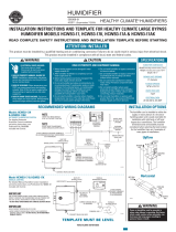
FAN POWERED HUMIDIFIER
INSTALLATION OPTIONS
Typical
Installation
Alternate
Installation
COOLING COILS IN
WARM AIR PLENUM
Humidifier to be
installed as
shown in relation
to cooling coils.
WIRING DIAGRAMS
90-847
90-922
Orientation of Humidifier
to Cooling Coils
WARNING
1. ELECTRICAL SHOCK HAZARD.
Disconnect electrical power to the furnace
and install lock-out tag before starting
i
nstallation. Failure to do so could result in
serious injury from electrical shock.
2.
SHARP EDGES HAZARD. Sharp
edges may cause serious injury from cuts.
Use care when making plenum openings
and handling ductwork.
3.
RISK OF SCALDING. Water
temperature over 125°F can cause severe
burns and scald instantly. Shut off the hot
water supply before disconnecting or
tapping into any hot water supply line.
SPECIFICATIONS
HUMIDIFIER DIMENSIONS
W
idth 15
29
⁄32”
Height (including solenoid valve
and drain spud)
18”
Depth 10
11
⁄32”
PLENUM OPENING
14
3
⁄4”W x 14
5
⁄16”H
WATER FEED RATE
6 gph
ELECTRICAL DATA
120 VAC-60 Hz, 0.8 AMP
CAUTION
1. Do not install humidifier where freezing temperatures
could occur. The water line could freeze and crack
causing water damage to the home.
2
. Do not install humidifier on the furnace cabinet.
3. Do not install humidifier on a plenum face where the
blanked off ends of the cooling coil will restrict air
movement through the humidifier.
4. Do not set humidity level above recommended or to
recommended level if condensation exists on inside
windows of any unheated space, as condensation
damage may result. Excess humidity can cause
moisture accumulation which can allow the possibility
for mold growth in the home.
5. Do not connect the humidifier power cord to multi-speed
furnace blower motors or blower motors other than 120 VAC.
Premature component failure may result.
6
. When installing Manual Humidifier Control on a downflow
furnace, ensure blower continues to run after a heat call is
satisfied to eliminate high temperatures from damaging the
Control.
7. Do not install humidifier where water pressure exceeds
125 psi, since damage to the humidifier may result. Follow
codes in effect concerning pressure reduction.
8. Do not install humidifier on the supply plenum where static
pressure exceeds 0.4 in. wg.
RISK OF PROPERTY AND EQUIPMENT DAMAGE.
BLANKED OFF
END OF COIL
NOTES
1. The humidifier is not suitable for installation on ducts
with horizontal airflow. Performance will be reduced.
2. When installing humidifier on a heat pump system, use
hot water. The heated water supplements the reduced
supply air temperature as added heat for evaporation.
HUMIDIFIER
24 VAC LEADS
C
HUM
24V COIL NORMALLY OPEN RELAY
(FIELD SUPPLIED PART# HN61KQ120)
MANUAL
HUMIDISTAT
HUMIDIFIER CORD
PLUGGED INTO
120 VAC POWER SOURCE
MANUAL
HUMIDISTAT
HUMIDIFIER CORD
PLUGGED INTO
120 VAC POWER SOURCE
FURNACE / AC
BLOWER MOTOR
COMMON LEAD
H
UMIDIFIER
24 VAC LEADS
CURRENT SENSING RELAY
PART NO. P-110-005
C
HI
LO
HUMIDIFIER
HUMIDIFIER CORD
PLUGGED INTO
120 VAC POWER SOURCE
24V COIL NORMALLY OPEN RELAY
(FIELD SUPPLIED PART# HN61KQ120)
HUM
C
24 VAC
LEADS
WARNING:
DO NOT CONNECT
FURNACE HUM
TERMINAL DIRECTLY
TO THERMIDISTAT
HUM TERMINAL
THERMIDISTAT™
CONTROL
INDOOR
UNIT
EQUIPMENT
CONTROLLER
C
HUM
24 VAC
LEADS
24V COIL NORMALLY OPEN RELAY
(FIELD SUPPLIED PART# HN61KQ120)
HUMIDIFIER
HUMIDIFIER CORD
PLUGGED INTO
120 VAC POWER SOURCE
HUMIDIFIER
24V COIL NORMALLY OPEN RELAY
(FIELD SUPPLIED PART# HN61KQ120)
24 VAC
LEADS
HUM
C
D
C
B
A
INDOOR
UNIT
HUMIDIFIER CORD
PLUGGED INTO
120 VAC POWER SOURCE
HumidiTrac
™
Automatic Humidifier Control
For detailed Automatic Humidifier
Control installation and wiring
instructions, see Form IM-AHC-02
included with Control.
DIAGRAM A
STANDARD FURNACE
VARIABLE SPEED FURNACE
VARIABLE SPEED FAN COIL
DIAGRAM B
STANDARD FAN COIL
DIAGRAM D
ZONING HOOK-UP
WITH EQUIPMENT CONTROLLER
DIAGRAM E
NEW COMMUNICATING CONTROL HOOK-UP
WITH ALL INDOOR EQUIPMENT
DIAGRAM C
THERMIDISTAT™ HOOK-UP WITH
ALL INDOOR EQUIPMENT
©2010 CAC/BDP
7310 West Morris St., Indianapolis, IN 46231
T EMPLATE M UST BE L EVEL
90-921
90-848
90-851
90-850
90-849
R
ETURN
R
ETURN
HOT WATER
S
UPPLY
S
UPPLY

READ COMPLETE SAFETY INSTRUCTIONS AND INSTALLATION TEMPLATE BEFORE STARTING
T EMPLATE M UST BE L EVEL
– TOP –
READ REVERSE SIDE FIRST! READ REVERSE SIDE FIRST!
Form/Catalog: IM-HUM-11
10007038 B2204133B 4.10
90-888
F
URNISHED ITEMS
2
4 VAC Manual Humidifier Control
S
addle Valve
Humidifier Installation Template
Mounting screws
(sheet metal screws)
Water supply line (
1
⁄4” copper)
D
rain line (
1
⁄2”
I.D. hose)
Low voltage wire
Manual Humidifier Control
Adapter Plate Part No. 4402
Current Sensing Relay
Part No. P-110-005 (if required)
I
TEMS NOT FURNISHED
IMPORTANT! Be sure owner’s manual containing instructions
for operation and warranty information is given to owner in order to avoid
unnecessary calls. Warranty is void unless humidifier is installed by qualified
heating and air conditioning contractor due to possible misapplication of product.
PARTS LIST
1. Front Cover
2. Base
3. Orifice Plate
4. Motor Mount Bridge
5. Scale Control Insert
6. Humidifier Pad
7. Water Distribution Tray
8. Fan Blade
9. Motor
10. Motor Mount Gasket
11. Control Circuit Board
12. Power Cord
13. Strain Relief Bushing
14. Solenoid Valve
15. Connector Plug
16. Feed Tube
NOTE: BEFORE LEAVING
THE JOB SITE, MAKE SURE:
1. Saddle valve is fully open.
2. All plumbing connections
are watertight.
3. Humidifier functions
properly.
1. Place the humidifier on a flat surface. Unlatch
humidifier cover assembly from base assembly
at the bottom of the cover, lift and set aside. Pull
out the evaporative assembly by grasping at the
top and tipping out. (See Figure 1)
2. Using a level, position this template at least
1
1
⁄ 2 inches above the furnace housing or
cooling coil if applicable, for clearance of the
drain line. Trace around template edges. When
there is insufficient space on the supply plenum,
the humidifier can be installed on the return duct
provided the humidifier is supplied with hot
water. Remove the template and accurately cut
the plenum opening 14
3
⁄4”W x 14
5
⁄16“H, being
careful to avoid injury from sharp edges.
3. Position the two plastic hooks on the top of
base along the top edge of the plenum opening.
Push base up to engage the two hooks and
sheet metal along the top edge opening. Push
base in and slide down so that the bottom four
hooks engage the sheet metal at the bottom
edge of the opening. Secure base to opening
using top three screw holes in housing. An
additional hole is provided at the bottom for
securing the base to the plenum. (See Figure 2)
4. While pressing the base against the plenum,
reach through the center opening and turn left
and right swing latches down to secure the
base onto the plenum. (See Figure 3)
5. Reinstall the evaporative assembly into the
base, with the bottom of the scale control insert
(5) sitting firmly in the inside of the drain spud
attached to the base. Push the evaporative
assembly in at the top between the retaining
ribs that hold the assembly in place in a vertical
position. Reinstall cover assembly by hooking at
the top of base assembly and latching at the
bottom.
6. Locate and install the Manual Humidifier
Control by following the instructions shown in
step #6A. For Automatic Humidifier Control
installation instructions, see Form IM-AHC-02
included with the Automatic Control.
DISCONNECT ELECTRICAL POWER TO
FURNACE BEFORE PROCEEDING!
6A. MANUAL HUMIDIFIER CONTROL INSTALLATION INSTRUCTIONS:
The Manual Humidifier Control is designed for low voltage service to control humidification equipment. An
increase in relative humidity expands the nylon ribbon that opens the control switch to stop operation of the
humidifier. A decrease in relative humidity reverses the process and closes the control switch.
LOCATION
1. Locate on inside wall of living area approximately
5 feet above floor, or in the furnace return air
plenum. Adapter Plate Part No. 4402 (not included)
is required for return plenum air installation. If
humidifier is mounted on return duct, Control must
be at least 6” upstream of humidifier.
2. Do not locate Control in the direct path of furnace
discharge air or drafts from open doors and
windows.
3. Do not install where operation might be affected
by lamps, sunlight, fireplace registers, radiators,
concealed air ducts and pipes, or room occupants.
4. The basic rules for location of thermostats also
apply to humidifier controls.
GENERAL INSTRUCTIONS
1. Do not attempt to repair or recalibrate
Humidifier Control. Humidifier Controls requiring
service should be returned to your distributor.
2. Use Humidifier Control in low voltage (24 VAC)
applications only. Install 24 VAC wiring to
Humidifier Control as shown in Wiring Diagrams,
opposite side.
3. Make sure no bare wires are exposed or
insulation damaged. Insulation on wire should
extend to head of screws.
4. Make sure all splices are mechanically and
electrically secure.
5. To remove dirt or other foreign matter from nylon
ribbon and control interior, dust lightly with a
fine, soft brush.
7. The humidifier power cord must be plugged into a
120 VAC outlet. Wire an electric outlet box to power
source other than furnace fan motor circuit. Outlet
box can be powered off of the 120 VAC line before it
enters furnace.
In order for the humidifier to turn on, the furnace
blower must be operating and the Humidifier Control
must be calling for humidity. The interface between
the humidifier and the furnace to detect blower
operation can be accomplished several different
ways. See wiring diagrams on other side for options.
8. Tap into water supply line with the saddle valve
furnished. See instructions on saddle valve package.
The humidifier will function with cold, hot, softened or
unsoftened water. The use of service hot water
(140°F MAX.) and constant blower operation will
provide maximum evaporative capacity. When
installing humidifier on heat pump system, humidifier
must be supplied with service hot water.
NOTE: The saddle valve is designed
to be fully opened or closed. Do not
u
se it to regulate water flow.
9. Connect tubing from the saddle
v
alve to the inlet side of the solenoid
valve using
1
⁄ 4” O.D. copper tubing
(not furnished). DOUBLE WRENCH TO
PREVENT LEAKING! (See Figure 4)
10. Drain spud is designed to accept
1
⁄ 2” I.D. plastic hose (not furnished).
Run drain line from drain spud to floor
drain. CAUTION: If hose clamp is used,
do not overtighten, drain spud could
crack. Make sure drain line has
constant downward slope and is not
kinked. NOTE: Do not sweat or directly
attach metal drain line to fitting. Do
not use solvent type adhesives when
connecting plastic drain line, since
damage to fitting could result.
11. Open saddle valve completely
and turn on furnace. Turn up
Humidifier Control so that humidifier
will turn on. Allow humidifier to run
until water is observed coming out of
the drain line. Check to see if
humidifier and saddle valve are
watertight. Check operation to make
sure that all electrical components
function properly. Set Humidifier
Control to level recommended in
Owner’s Manual.
Figure 1
90-923 90-924 90-925 90-926
Figure 2 Figure 3 Figure 4
6
5
7
1
3
9
11
13
12
14
15
8
10
4
2
16
17
/