Page is loading ...

127
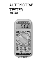
Digital Automotive Multimeter
Read this manual thoroughly before use
Users Manual

1
This instrument is warranted to be free from defects in material
and workmanship for a period of one year. Any instrument
found defective within one year from the delivery date and
returned to the factory with transportation charges prepaid, will
be repaired, adjusted, or replaced at no charge to the original
purchaser. This warranty does not cover expandable items
such as battery or fuse. If the defect has been caused by a
misuse or abnormal operating conditions, the repair will be
billed at a nominal cost.
WARRANTY
This meter is a compact 3 1/2-digit digital automotive
multimeter. In addition to the features of a normal multimeter,
it can also be used to measure RPM, dwell angle, duty cycle,
battery, temperature, ignition system, and etc. It is very
useful and is an ideal measurement tool for automotive repair
and service.
It can be used to measure:
1. RPM of engine
2. Dwell angle
3. Battery
4. Duty cycle
5. DC voltage
6. DC current
INTRODUCTION

2
7. Resistance
8. Frequency
9. Diode
10. Continuity
11. Temperature
12. Ignition system
Warning
To avoid possible electric shock or personal injury, follow
these guidelines:
1. Do not use the meter if it is damaged. Before you use
the meter, inspect the case. Pay particular attention to
the insulation surrounding the connectors.
2. Inspect the test leads for damaged insulation or exposed
metal. Check the test leads for continuity. Replace
damaged test leads before you use the meter.
3. Do not use the meter if it operates abnormally. Protection
may be impaired. When in doubt, have the meter
serviced.
4. Do not operate the meter around explosive gas, vapor,
or dust.
5. Do not apply more than the rated voltage, as marked on
the meter, between terminals or between any terminal
and earth ground.
6. Before use, verify the meter's operation by measuring a
known voltage.
7. When measuring current, turn off circuit power before
connecting the meter in the circuit. Remember to place
the meter in series with the circuit.

3
8. When servicing the meter, use only specified
replacement parts.
9. Use caution when working with voltage above 30V ac
rms, 42V peak, or 60V dc. Such voltages pose a shock
hazard.
10. When using the probes, keep your fingers behind the
finger guards on the probes.
11. When making connections, connect the common test
lead before you connect the live test lead. When you
disconnect test leads, disconnect the live test lead first.
12. Remove the test leads from the meter before you open
the battery cover or the case.
13. Do not operate the meter with the battery cover or portions
of the case removed or loosened.
14. To avoid false readings, which could lead to possible
electric shock or personal injury, replace the batteries as
soon as the low battery indicator ( ) appears.
15. To avoid electric shock, do not touch any naked conductor
with your hand or skin. Do not ground yourself while using
the meter.
16. Comply with local and national safety requirements. Use
correct protective equipment when you work in hazardous
areas.
17. Always follow vehicle manufacturer's warnings, cautions
and service procedures.
18. Never smoke or have open flames near vehicle.
19. Always operate the vehicle in a well ventilated area. Do
not inhale exhaust gases or fuel vapors.

4
Caution
To avoid possible damage to the meter or to the equipment
under test, follow these guidelines:
1. Disconnect circuit power and discharge all capacitors
before testing resistance, diode, continuity and
temperature.
2. Use the proper terminals, function and range for your
measurements.
3. Before rotating the range switch to change functions,
disconnect test leads from the circuit under test.
Symbols
Direct Current
Caution, risk of danger, refer to the operating manual
before use.
Caution, risk of electric shock.
Earth (ground) Terminal
Fuse
Conforms to European Union directives
The equipment is protected throughout by double
insulation or reinforced insulation.

STRUCTURE
1. Display
3
1
/2 digit LCD, with a max. reading of 1999
2. " Low " LED / " HV " LED
a. In ignition system test, this LED will flash if the spark
plug wire is delivering spark.
b. In battery test, this LED will light if the battery is low.
3. " Normal " LED
In battery test, this LED will light if the battery is normal.
4. " High " LED
In battery test, this LED will light if the battery is high.
7 8 9
10
11
1
2
3
4
5
6
5
Figure 1

5. Power Switch
Used to turn on or off the meter.
6. Function / Range Switch
Used to select desired function and range as well as to
turn on off the meter.
7. " 10A " Terminal
Plug-in connector for the red test lead for current
measurements.
8. " COM " Terminal
Plug-in connector for the black test lead.
9. " INPUT " Terminal
Plug-in connector for the red test lead for all
measurements except current measurements
10. Holster
11. " HOLD " Button
Used to enter or exit Data Hold mode.
6

7
GENGRAL SPECIFICATION
Fuse Protection for " 10A " Jack Inputs: 10A/250V Fast
Fuse
Display: 3
1
/2-digit LCD, with a max. reading of 1999
Overrange Indication: only figure " 1 " shown on the
display
Negative Polarity Indication: " - " displayed automatically
Sampling Rate: about 2~3 times/sec
Operating Environment: temperature: 0°C ~ 40°C
relative humidity: < 75%
Storage Environment: temperature: -20°C ~ 60°C
relative humidity: < 85%
Operating Altitude: 0 to 2000 meters
Battery: 9V, 6F22 or equivalent
Low Battery Indication: " " shown on the display
Dimensions: 156X78X58mm
Weight: about 290g ( including battery )

8
**
DC Current
Max. Permitted Input: 10A
( For inputs > 2A: measurement duration < 10 secs,
interval >15 minutes )
Overload Protection: Fuse, 10A/250V, Fast action
10A 0.01A ± (2.0%+5)
Input Impedance: 10M
20V
35V
0.01V
0.1V
± (0.5% + 5)
± (1.0% + 5)
SPECIFICATIONS
Accuracy is specified for a period of one year after
calibration and at 18°C to 28°C, with relative humidity < 75%.
Accuracy specifications take the form of:
± ([% of Reading]+[number of Least Significant Digits])
DC Voltage
ResolutionRange Accuracy
ResolutionRange Accuracy

9
Frequency
20kHz
0.01kHz ± (1.5%+5)
Measurement Range: 1Vp ~ 35Vp
Duty Cycle
5% ~ 95% 0.1% ± (2.5%+5)
Measurement Range: 6Vp ~ 35Vp
Frequency Range: 40Hz ~ 1kHz
Resistance
200
2k
20k
200k
0.1k
0.001k
0.01k
0.1 ± (1.2%+5)
± (1.0%+5)
20M 0.01M ± (1.5%+5)
ResolutionRange Accuracy
ResolutionRange Accuracy
ResolutionRange Accuracy

Range Description
Diode and Continuity
*** ****
0°C ~ 400°C: ± (1.5%+5)
1°C
> 400°C: ± (2.0%+5)
Temperature
0°C ~ 1000°C
Resolution AccuracyRange
10
Open Circuit Voltage:
about 2.8V
Test Condition
Open Circuit Voltage:
about 2.8V
The approx. forward
voltage drop of the
diode will be displayed.
The built-in buzzer will
sound if the resistance
is less than about 30 .
Note :
1. The above accuracy does not include error of the
thermocouple probe.
2. Accuracy specification assumes ambient temperature
is stable to ±1°C. For ambient temperature changes of
±5°C, rated accuracy applies after 1 hour.

Battery
12V
24 0.1V
0.01V
Resolution DescriptionRange
Note: Do not measure a battery whose rating is higher than
24V.
10RPM ± (2.5%+5)
Measurement Range: 6Vp ~ 35Vp
For 4-stroke engines:
actual rotation speed = displayed reading × 10;
For 2-stroke engines:
actual rotation speed = 50% × ( displayed reading × 10 )
Tach ( rotation speed )
0RPM ~
20000RPM
If the battery is low, the "Low"
LED will light. If the battery is
normal, the "Normal" LED will
light. If the battery is high, the
"High" LED will light.
The display will show the approx.
voltage at the same time.
11
Range
Number of
Cylinders
Accuracy
The Highest
Resolution
3 cylinders
4 cylinders
5 cylinders
6 cylinders
8 cylinders

12
OPERATION INSTRUCTION
Data Hold Mode
Press the " HOLD " button to hold the present reading on the
display. " " appears on the display as an indicator. To exit
the Data Hold mode, press the button again. " " disappears.
0.1
°
± (2.5%+5)
Input Voltage: 6Vp ~ 35Vp
Rotation Speed of Engine: 0RPM ~ 20000kRPM
Dwell Angle
0 ~ 120
°
0 ~ 90
°
0 ~ 72
°
0 ~ 60
°
0 ~ 45
°
3 cylinders
4 cylinders
5 cylinders
6 cylinders
8 cylinders
Range
Number of
Cylinders
AccuracyResolution

13
1. Connect the black test lead to the " COM " jack and the
red test lead to the " INPUT " jack.
2. Set the range switch to desired range.
3. Connect the test leads across the circuit or source to be
measured.
4. Read the reading on the display. The polarity of the red
lead connection will be indicated as well.
Note :
To avoid damages to the meter, do not attempt to measure a
DC voltage higher than 35V although readings may be
obtained.
Measuring DC Voltage
Figure 2

Measuring DC Current
14
1. Connect the black test lead to the " COM " jack and the
red test lead to the " 10A " jack.
2. Set the range switch to position.
3. Turn off power to the circuit which you want to measure.
Discharge all capacitors.
4. Break the circuit path to be measured, connect the test
leads in series with the circuit.
5. Turn on power to the circuit, then read the display. The
polarity of the red test lead connection will be indicated as
well.
Note:
1. Never attempt to perform an in-circuit current
measurement when the open circuit potential to earth is
more than 35V.
Figure 3

Measuring Resistance
1. Connect the black test lead to the " COM " jack and the
red test lead to the " INPUT " jack. ( Note:The polarity of
the red lead is positive " + ". )
2. Set the range switch to desired range.
3. Connect the test leads across the load to be measured.
4. Read the reading on the display.
Note :
1. For measurements > 1M , the meter may take a few
R
15
2. Don't use the meter to measure a current higher than 10A.
3. Never place the probes in parallel with a circuit or
component when the test leads are plugged into the
current terminals.
Figure 4

1. Connect the black test lead to the " COM " jack and the
red test lead to the " INPUT " jack. ( Note:The polarity of
the red lead is positive " + ". )
2. Set the range switch to position.
Continuity Test
16
seconds to stabilize reading. This is normal for high
resistance measurements.
2. When the input is not connected, i.e. at open circuit, "1"
will be displayed as overrange indication.
3. To avoid electric shock to you or damage to the meter,
disconnect circuit power and discharge all capacitors
before measuring resistance.
Figure 5

1. Connect the black test lead to the " COM " jack and the
red test lead to the " INPUT " jack.
2. Set the range switch to 20kHz position.
Measuring Frequency
17
3. Connect the test leads to the circuit to be measured.
4. If the resistance is less than about 30 , the built-in buzzer
will sound.
Note:
To avoid electric shock to you or damage to the meter,
disconnect circuit power and discharge all capacitors before
test.
Figure 6

Diode Test
1. Connect the black test lead to the " COM " jack and the
red test lead to the " INPUT " jack. ( Note:The polarity of
the red lead is positive " + ". )
18
3. Connect the test leads across the source or load to be
measured.
4. Read the reading on the display.
Note:
The input voltage should be between 1Vp and 35Vp. If the
voltage exceeds 35Vp, the accuracy of reading may be out
of the specified accuracy range.
Figure 7

Measuring Duty Cycle
1. Connect the black test lead to the " COM " jack and the
red test lead to the " INPUT " jack.
2. Set the range switch to Duty position.
3. Connect the red test lead to the positive terminal of the
signal source be measured and the black test lead to the
19
2. Set the range switch to position.
3. Connect the red test lead to the anode of the diode to be
tested and the black test lead to the cathode of the diode.
4. The display shows the approximate forward voltage drop
of the diode. If the connection is reversed, "1" will be
shown on the display.
Figure 8
/