14 Exterior 200 LED user manual
Control data link
Exterior 200 LED fixtures must be connected via a control data link for DMX controller or synchronized
(master/slave) operation.The following considerations must be taken into account when planning the data
link:
• RS-485 data cable designed for exterior use is required for outdoor installations. RS-485 cable has low
capacitance and a characteristic impedance of 85 to 150 Ohms. It is electrically shielded and has at least
1 twisted pair of conductors. The minimum recommended wire size is 0.25 mm
2
(24 AWG) for runs up to
300 meters (1000 ft.) and 0.32 mm
2
(22 AWG) for runs up 500 meters (1640 ft). CAT 5 network cable
designed for direct burial can be used in outdoor installations, but you are recommended to run it inside
conduit.
• The maximum permitted control data cable length before a control signal amplifier is required is 500
meters (1640 ft.).
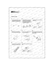
• Fixtures must be ‘daisy-chained’, i.e. the data
cable must be connected in one single chain of
fixtures as shown in Figure 7.
• Each chain may connect a maximum of 32
fixtures.
• An optically isolated amplifier-splitter such as the
Martin RS-485 Opto-Splitter (P/N 90758060)
must be used to:
- extend a link beyond 500 meters (1640 ft.)
- extend the link to include a further maximum
32 fixtures, or
- branch the link into further single chains, each
containing 32 fixtures. The Martin
Opto-Splitter allows a link to be branched into
four new chains.
• Each chain on the link must be terminated by
placing a 120 ohm resistor (available from Martin,
P/N 04150308) across the data hot (+) and cold
(-) conductors of the last fixture on the chain.
• Long parallel runs of AC power and control data cables may cause interference on the data link and must
be avoided. Even if not required by law, use separate conduits for power and data cables.
• One DMX universe has 512 DMX control channels available. If individual control of the fixtures in an
installation is required, each fixture must be given its own channels until the limit of 512 is reached. At this
point, a new DMX universe must be created before more fixtures can be added.
• The number of fixtures that can be individually controlled in one DMX universe depends on the number of
DMX channels they use. if Exterior 200 LED fixtures are set to HSI mode, each fixture require 3 DMX
channels (one channel for hue, one for saturation and one for intensity). The total number of Exterior 200
LED fixtures that can be linked in one DMX universe will therefore be 512/3 = 170.
Connection pinouts
XLR connection
XLR connectors are suitable if DMX cable is used for the data link. XLR pin numbers are normally marked
on connectors. Connectors must be wired using the standard XLR DMX pin-out:
• Pin 1: Cable shield
• Pin 2: DMX Data 1 - (cold)
• Pin 3: DMX Data 1 + (hot)
Pins 4 and 5 on 5-pin XLR connectors are available for Data 2 connections in DMX 512-A or similar
systems. They must be wired as follows:
• Pin 4: DMX Data 2 - (cold)
• Pin 5: DMX Data 2 + (hot)
To avoid ground/earth loop interference, ensure that the DMX cable shield does not come into contact with
the shell or body of XLR connectors.
Figure 7: DMX link