1384
SHR cover
5/27/99 djt
SHR Series
Woodburning Fireplace
For Models:
SHR36
SHR42A
SHR48
SHR52
Underwriter's Laboratories Report No. MH6018
DO NOT DISCARD THIS MANUAL: Retain for future use.
20001384 4/07 Rev. 19
Homeowner's Installation
and Operating Manual

2
SHR Series Woodburning Fireplace
20001384
Safety Information
PLEASE READ THIS MANUAL BEFORE INSTALLING AND USING FIREPLACE.
IMPORTANT:
Read all instructions and warnings carefully before starting installation. Failure to
follow these instructions may result in a possible fire hazard and will void the warranty.
Description
The SHR Series fireplaces are solid fuel, woodburn-
ing fireplaces. The SHR36/42A/48 (Super Hearth) are
clean-face fireplaces.
Precautions
CFM Corporation fireplaces and component parts have
been highly tested and will operate safely when in-
stalled in accordance with instructions provided in this
manual. Carefully read and understand all instructions
before beginning installation.
If you notice any damage to fireplace or component
parts, immediately report damage to your Majestic Fire-
places dealer.
Only use CFM Corporation components or the warranty
will be voided and a fire hazard may be created.
CFM Corporation warranty will be voided by and CFM
Corporation disclaims any responsibility for the follow-
ing actions:
• Installation by any other than a qualified
installer, preferably NFI or WETT (Canada)
certified.
• Installation of any damaged fireplace or chim-
ney component;
• Modification of fireplace, chimney assembly
or any component parts thereof; (except for
chase flashings as detailed in the Chimney
Top installation instructions).
• Installation other than as instructed by CFM
Corporation; or
• Installation and/or use of any component part
not manufactured or approved by CFM Corpo-
ration in combination or assembly with a CFM
Corporation fireplace system, notwithstanding
any independent testing laboratory or other
third party approval of such component parts
or accessory.
Any such action may possibly cause a fire hazard.
Consult local building codes to ensure that you are in
compliance before installing the fireplace.
Fireplaces must be vented to the out-of-doors.
Do not obstruct or modify air inlets/outlets in any
manner.
Do not install combustible materials on any of the
black fireplace surround.
Burn only solid wood fuel or gas logs.
Do not install a solid fuel burning insert or other
products not specified for use with this fireplace.
Proposition 65 Warning:
Fuels used in gas, wood-
burning or oil fired appliances, and the products of
combustion of such fuels, contain chemicals known
to the State of California to cause cancer, birth de-
fects and other reproductive harm.
California Health & Safety Code Sec. 25249.6
WARNING: Check with your electronics manufac
-
turer before installing a television or other electron-
ic device above this fireplace.
Drafts
The fireplace should not be located in areas that create
drafts (ie: frequently opened doors and central heating
air inlets/outlets) that hamper the normal flow of air into
the fire.
Gas Logs
If you plan to install a gas log, the gas line should be
installed before framing the fireplace. The gas line must
be installed by a certified gas line installer.
SHR36 / SHR42A / SHR48 / SHR52
Listed
UL 127 / ULC-S610
Standard for Factory Built Fireplaces
Safety Information . . . . . . . . . . . . . . . . . . 2
Specifications and Framing
. . . . . . . . . . 3
Parts Identification
. . . . . . . . . . . . . . . . . 5
Chimney Requirements . . . . . . . . . . . . . 6
Planning Information . . . . . . . . . . . . . . . . 7
Installation . . . . . . . . . . . . . . . . . . . . . . . 8
Replacement Parts . . . . . . . . . . . . . . . . 20
Accessories . . . . . . . . . . . . . . . . . . . . . 21
Table of Contents

3
SHR Series Woodburning Fireplaces
20001384
Rough
Opening
Height
42" (1067mm)
52" (1327mm)
48
"
(1222mm)
"
"
28"
(724mm)
"
(189mm)
13" Dia.
(340mm)
Rough Opening Width 53"
Rough
Opening
Depth
65" (1654mm)
65" (1654mm)
" (2340mm)
"
(267mm)
"
(743mm)
" (826mm)
54"
(1378mm)
"
(1172mm)
" (19mm)
"
" (19mm)
12"
(311mm)
FP546A
SHR42 specs
6/15/99 djt
11" Dia.
(279mm)
19"
(489mm)
14
"
(362mm)
9"
(229mm)
10
"
(258mm)
Outside
Air
Gas Line Access
Gas Line
Access
(1365mm)
FP546A
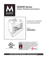
Fig. 2 SHR42A Series specifications and framing.
SHR42A Series Woodburning Fireplace
36"
(914mm)
46" (1175mm)
44"
(1118mm)
"
"
"
(610mm)
"
(189mm)
13" Dia.
(340mm)
Rough Opening Width 47"
Rough
Opening
Height
Rough
Opening
Depth
57" (1472mm)
57" (1472mm)
" (2080mm)
"
(2264mm)
"
(680mm)
" (737mm)
48
"
(1226mm)
"
(1056mm)
" (19mm)
"
" (19mm)
12"
(318mm)
FP546A
SHR36 Specs
5/18/99 djt
11" Dia.
( 279mm)
13"
(349mm)
7"
(197mm)
"
(368mm)
"
(397mm)
Outside
Air
Gas Line Access
Gas Line
Access
(1213mm)
SHR36 Series Woodburning Fireplace
FP526A
Fig. 1 SHR36 Series specifications and framing.

4
SHR Series Woodburning Fireplace
20001384
"
(724mm)
7"
(197mm
)
48"
(1219mm)
58" (1480mm)
48" (1232mm)
"
"
"
(189mm)
13" Dia.
(340mm)
Rough Opening Width 59"
Rough
Opening
Height
Rough
Opening
Depth
66" (1686mm)
66" (1686mm)
" (2384mm)
"
(264mm)
"
(680mm)
" (1041mm)
53" (1346mm)
"
(1208mm)
" (19mm)
"
" (19mm)
12"
(318mm)
FP545A
SHR48 specs
6/15/99 djt
11" Dia.
(279mm)
15"
(397mm)
13
"
(349mm)
14
"
(368mm)
Outside
Air
Gas Line Access
Gas Line
Access
(1518mm)
SHR48 Series Woodburning Fireplace
Fig. 3 SHR48 Series specifications and framing.
FP545A
9"
(235mm)
52"
(1321mm)
62" (1584mm)
52" (1334mm)
"
"
(838mm)
"
(189mm)
13" Dia.
Rough Opening Width 63"
Rough
Opening
Height
Rough
Opening
Depth
74" (1886mm)
74" (1886mm)
105" (2667mm)
"
(216mm)
"
(794mm)
" (1041mm)
68
"
(1749mm)
"
(1334mm)
12" (305mm)
1384
SHR52 specs
10/02 djt
11" Dia.
23"
(584mm)
13
"
(343mm)
12
"
(318mm)
Outside
Air
Gas Line Access
Gas Line
Access
"
" (19mm)
"
" (19mm)
Standoff
Notch
(1622mm)
(340mm)
(279mm)
SHR52 Series Woodburning Fireplace
Fig. 4 SHR52 Series specifications and framing.

5
SHR Series Woodburning Fireplaces
20001384
FP554A
SH Series
1/28/99 djt
Chase Installation
Insulation methods shown are optional
for cold climate, not a requirement for unit
operation.
FP554A
Fig. 5 Fireplace and chase parts identification. (SHR48 shown)
Termination Cap
Storm Collar
Pan Flashing
Batt Insulation
(cut out around
firestop)
Firestop
Ceiling Level
Draftstop
Ledge Bracket
Surround
Damper Control
Gas Line Knockout
(both sides)
Screen
Grate
Firebox
Metal Safety
Strips (1,2 or 3)
Outside Air
Cover Plate
Gas Line Access
(both sides)
A
B
C
FP1531
hearth dimensions
9/04 djt
Front Width Back Width Depth
A B C
SHR36 35
³⁄₄" 22" 20³⁄₈"
(908 mm) (559 mm) (516 mm)
SHR42A 41
⁷⁄₈" 26⁵⁄₈" 23³⁄₈"
(1064 mm) (676 mm) (594 mm)
SHR48 47³⁄₄" 34" 20¹⁄₄"
(1213 mm) (864 mm) (514 mm)
SHR52 52" 34¹⁄₂" 25¹⁄₄"
(1321 mm) (876 mm) (641 mm)
FP1531
Fig. 4a Hearth dimensions.

6
SHR Series Woodburning Fireplace
20001384
Chimney Requirements - Offset Installations
0 0 0 0 0 3" 11"
1 0 0 0 0 8
¹⁄₄" 20"
0 1 0 0 0 11
¹⁄₄" 25¹⁄₄"
2 0 0 0 0 13¹⁄₂" 29¹⁄₄"
1 1 0 0 0 16
¹⁄₂" 34¹⁄₄"
0 0 1 0 0 20
¹⁄₄" 40³⁄₄"
2 1 0 0 0 21
³⁄₄" 43¹⁄₂"
0 0 0 1 0 26
¹⁄₄" 51¹⁄₄"
0 1 1 0 0 28¹⁄₂" 55¹⁄₄"
1 0 0 1 0 31
¹⁄₂" 60¹⁄₄”
0 1 0 1 0 34
¹⁄₂" 65¹⁄₂"
0 0 2 0 0 37¹⁄₂" 70³⁄₄"
1 1 0 1 1 41
¹⁄₂" 77³⁄₄"
0 0 1 1 1 45" 83
³⁄₄"
0 1 2 0 1 47¹⁄₄" 87¹⁄₂"
0 0 0 2 1 51" 94"
0 1 1 1 1 53¹⁄₄" 98"
0 0 3 0 1 56¹⁄₄" 103¹⁄₄"
0 1 0 2 1 59
¹⁄₄" 108¹⁄₂"
0 0 2 1 1 62
¹⁄₄" 113¹⁄₂"
0 1 3 0 1 64
¹⁄₂" 117¹⁄₂"
0 0 1 2 1 68
¹⁄₄" 124"
0 1 2 1 1 70¹⁄₂" 128"
0 0 0 3 1 74
¹⁄₄" 134¹⁄₂"
0 1 1 2 2 78" 140
³⁄₄"
0 0 3 1 2 81" 146"
0 1 0 3 2 84" 151
¹⁄₄"
0 0 2 2 2 87" 156
¹⁄₂"
0 1 3 1 2 89¹⁄₄" 160¹⁄₄"
0 0 1 3 2 93" 166
³⁄₄"
0 1 2 2 2 95
¹⁄₄" 170³⁄₄"
0 0 0 4 2 99
¹⁄₄" 177³⁄₄"
0 1 1 3 2 101
¹⁄₄" 181³⁄₄"
0 0 3 2 2 104¹⁄₄" 186¹⁄₄"
0 1 0 4 2 107
¹⁄₄" 191¹⁄₂"
0 0 2 3 2 110
¹⁄₄" 196³⁄₄"
0 1 3 2 3 114" 203¹⁄₄"
0 0 1 4 3 117
³⁄₄" 209³⁄₄"
0 1 2 3 3 120" 213
¹⁄₂"
0 0 0 5 3 123³⁄₄" 220"
30˚ Elbow Offsets
1'
1¹⁄₂'
3' 4'
Chimney
Support
Offset
Rise
Notes: G + H cannot exceed 20 feet.
*11CF Chimney airspace clearance = 2" minimum.
Illustration Key
The following safety rules apply to offset
installations (letters correspond with illustra-
tion above):
A. Height of the chimney is measured from
the hearth to the chimney exit.
SHR36 SHR42A SHR48 SHR52
Max.: 90' 90' 90' 90'
Min.:
0 Elbows 14'6" 14'6" 16'0" 16'0"
2 Elbows* 15'6" 15'6" 19'0" 19'0"
4 Elbows* 21'0" 21'0" 24'0" 24'0"
B. Do not use more than 4 elbows per chim-
ney.
Attach the straps of the return (top) elbow to a
structural framing member.
The offset (first) elbow of any pair does not
have straps.
FP269
C. The chimney cannot be more than
30˚ from the vertical plane in any instal-
lation.
D. The maximum length of the angled
run of the total chimney system is 20
feet. (G plus H cannot exceed 20 feet.)
E. A chimney support (Model 11CS)
is required every 6 feet of angled run
of chimney. Chimney supports are
required for every 30 feet and 60 feet
chimney height above the hearth.
Determine the offset distance of your
chimney arrangement from the center-
line of the fireplace to the centerline of
the chimney where it is to pass through
the first ceiling.
NOTE: This offset distance may not be
your full offset distance. See Examples
2 and 3.
IWF282
MBUF
5/26/96
Offset
Rise
FP282
Fig. 6 Chimney system requirements.
D
B
G
H
B
C
E
6 FT.
G
H
A
IWF269
MBUF
5/16/96
rev. 5/25
30°
Return
Elbow
Chimney Flue Exit
Chimney
Section
Rise
30°
Offset
Elbow
11CS Sup
-
port
Offset
30°
Offset
Elbow
30°
Return
Elbow
Example 1 Example 2
Example 3
Elbow
Hearth Floor

7
SHR Series Woodburning Fireplaces
20001384
Planning Information
The Ten Foot Rule
Major U.S. building codes specify a minimum chimney
height above the roof top. The “Ten Foot Rule” is a fire
safety rule and not a draft rule. To ensure proper draft,
it is recommended that you always meet or exceed the
“Ten Foot Rule,” especially when installing a termination
on a high pitch roof. (Fig. 8)
The key points of the "Ten Foot Rule" are:
1. If the horizontal distance from the chimney to the
peak of the roof is 10' (3m) or less, the top of the
chimney must be at least 2' (610mm) above the peak
of the roof, but never less than 3' (914mm) in height
above the highest point where it passes through the
roof.
2. If a horizontal distance from the chimney to the peak
of the roof is more than 10' (3m), a chimney height
reference point is established that is on the surface
of the roof a distance of 10' (3m) from the chimney in
a horizontal plane. The top of the chimney must be
at least 2' (610mm) above the reference point, but
never less than 3' (914mm) in height above the high-
est point where it passes through the roof.
In planning a chimney system, it is important to know:
1. The height of a chimney is measured from the
hearth to the exit point on the termination.
2. A chimney cannot be offset more than 30 degrees
from a vertical plane.
3. A chimney may run straight up or it may be neces-
sary to offset it to avoid obstructions.
4. The maximum length of an angled run (total chimney
system) is 20 feet.
5. No more than 2 offsets (4 total 30˚ elbows in) per
fireplace may be used.
6. A guy wire stabilizer is required for chimneys extend
-
ing more than 6 feet above a roof line.
Preplanning an installation is very important to ensure
safety and to save time and money. An installer must
predetermine where a fireplace will be set and how the
chimney system will be run.
Mounting the Fireplace
A fireplace may only be mounted on the following sur-
faces:
1. A flat combustible surface.
2. A raised wooden platform.
3. A concrete block or other solid object placed beneath
each of the four (4) corners of the fireplace.
The fireplace must be spaced 3/4 inch from a combus-
tible back wall and 3/4 inch from a combustible side
wall or support. (Fig. 20, Page 14)
Planning the Chimney Run
Determine how the chimney will be run, length of run
and chimney components required to complete the
job. (Fig. 6) Never install a chimney below minimum
heights.
Fig. 7 Installed lengths of chimney sections.
FP288b
L
1
L
1
L
T
11CF
Chimney
Model No.
Total
Length
(L
T
)
Installed
Length
(L
1
)
11CF1
11CF18
11CF3
11CF4
"
"
"
"
"
"
"
"
FP288B
11CF
SHR SERIES
5/11/99 djt
AC246
Fig. 8 Ten Foot Rule illustration.
2' Min.
2' Min.
3'
Min.
0 To 10'
3'
Min.
0 To 10'
AC246
4/1/96
Reference
Point

8
SHR Series Woodburning Fireplace
20001384
Installation
Chimney Supports
The chimney system is supported by the fireplace for
vertical chimney heights less than 30 feet above the
hearth. Chimney supports are required if the vertical
height exceeds 30 feet with 11CF chimneys. Locate
chimney supports at ceiling holes or other structural
framing at 30 foot heights. Spacing between chimney
supports must not exceed 30 feet. Use Chimney
Support Model 11CS. (NOTE: The 11CS can not be
mounted directly to the fireplace.) Support provided
by elbow straps fulfills the support requirement only if
they are spaced as previously described. (A chimney
support is 2¹⁄₂" long when installed.)
Angled chimney runs require a support every six (6)
feet in addition to the elbow straps. Chimney supports
are used for this function. (Fig. 9)
Chase Installation
A chase is a vertical boxlike structure which encloses
the fireplace and/or chimney. Chases are typically built
on the outside of the house with fireplace opening cut
into the outer wall of a room. (Page 5, Fig. 5)
If you need help in determining fireplace location or how
the chimney system should be run, contact your Majes-
tic Fireplaces dealer for assistance.
Insulating Fireplace
Enclosure for Cold Climates
If you live in a cold climate, it is not required but
highly recommended that you insulate the fireplace
enclosure to eliminate cold air penetration as much
as possible.
Insulate base of fireplace with a noncombustible
insulation rated for a minimum of 300° F. Insulating
is very important for outside wall installations over
a concrete slab. If fireplace is installed on a platform,
insulation should be placed on top of the platform
before fireplace is set. (Fig. 10)
When a fireplace is installed in a chase or on an
outside wall, enclosure should be treated like any
outside wall in a home. Insulation should be installed
on the inside wall as well as the outside wall(s). In
a chase, it is also a good idea to install a firestop at
the first ceiling level above the fireplace and enclose
the chase with sheeting material. Insulation may
then be installed above sheeting material to assure
the space around the fireplace is totally protected.
(Fig. 5)
CAUTION: WHEN INSTALLING A FIREPLACE IN
AN INSULATED ENCLOSURE, BE SURE ALL RE-
QUIRED AIR SPACES ARE MAINTAINED. (Page
15, Fig. 19)
IWF284
MBUF
5/25/96
FP284
Fig. 9 Chimney support installation
Chimney Support
Strap
11CS

9
SHR Series Woodburning Fireplaces
20001384
Framing
Framing can be constructed before or after the fireplace
is set in place, however, most installers build the frame
before setting the fireplace.
Frame fireplace with 2 x 4 lumber or heavier materials.
Refer to framing dimensions in Figures 1 - 4 for basic
fireplace specifications.
NOTE: Framing should be positioned to accommodate
wall covering and fireplace facing material.
Firebrick Installation
For the SHR52 model the firebrick is packed separately
and must be installed in the fireplace.
You will need four (4) firebrick, three (3) brick retainers,
a phillips head screwdriver, and the grate.
The side and rear firebrick each have a notch in the top
of the brick panel. The side firebrick have a notch in the
lower front side of each panel. The herringbone pattern
faces out of the fireplace always. (Fig. 11)
NOTE: The screens and screen rod smoke baffle as-
sembly must be removed and set aside before proceed-
ing. Remove the two screws holding the screens place.
There are seven screws holding the screen rod smoke
baffle in place.
1. Remove the three brick retainers from the combus-
tion dome by removing the phillips screws, set aside.
2. Set the left firebrick in place on the left side of the
fireplace.
3. Slide the rear firebrick back into the left corner be
-
hind the end of the left firebrick. Push both panels back
as far as possible into the left side and corner.
4. Swing the right side of the back firebrick into place.
Attach the left brick in place using a brick retainer at the
top and phillips screw removed earlier.
5. Slide the right firebrick into place as far back as pos
-
sible. Attach rear firebrick and right firebrick using brick
retainers and phillips screws removed earlier.
6. Slide the hearth firebrick into the grate clip. (Fig. 12)
The grate will be used as a handle to set the hearth
firebrick in place.
7. With the hearth firebrick securely in place in the
grate clip, carefully lift the hearth firebrick into the
fireplace, set the rear of the firebrick down, then slide
back to meet the rear firebrick. Gently set the front of
the firebrick in place. Replace screens and screen rod
smoke baffle assembly.
FP555
Platform, insulation
11/10/97
5/11/99 djt
FP555SHR
Fig. 10 Insulating between platform and fireplace.
Hard, Flat
Surface
Insulation
Platform
FP1234
SHR52
Firebrick
12/10/02
Rear Firebrick
Brick
Retainer
Side Firebrick
Front
Notch
FP1234
Fig. 11 SHR52 Firebrick installation.
Chimney Set-up
Since you have already preplanned the chimney run,
you should know exactly how the installation is to be
accomplished — how much pipe is required, the num-
ber of elbows, if any, and type of termination to be used.
FP1235
SHR52
hearthbrick
12/10/02 djt
Grate
Grate Clip
Hearth
Firebrick
FP1235
Fig. 12 Hearth firebrick in place in grate clip.

10
SHR Series Woodburning Fireplace
20001384
FP556SHR
Fig. 13 Locate centerline of chimney with plumb line.
FP556SHR
SHR
LOCATE CENTER LINE
5/11/99 djt
Chimney Centerline
Actual Centerpoint
Plumb Line
Plumb Bob
Imaginary
Centerpoint
11
¹⁄₈"
(283 mm)
FP 548b
SHR
5/11/99 djt
Angle of Chimney at Ceiling
Size of Chimney
Vertical
30˚
11" CF 2-Wall
FS2A
17" x 17"
(445 x 445 mm)
FS6A
17" x 29"
(454 x 753 mm)
CHIMNEY HOLE SIZE
Fig. 14 Ceiling chimney hole size necessary for installing
firestop spacer.
CAUTION: REPORT TO YOUR DEALER ANY PARTS
DAMAGED IN SHIPMENT, SPECIFICALLY CHECK
THE END CONNECTION OF CHIMNEY SECTIONS
AND ELBOWS.
NOTE: SHR Series Fireplaces must use CFM Corpora-
tion model 11CF, 11 inch, 2 wall chimney systems. The
installation procedure described in this manual applies
only to the 11CF system, chimney components may
not be mixed.
Straight-Up Chimney Installation
To mark the centerline of the flue, put the fireplace in
final position and measure out from the wall 11¹⁄₈". Mark
a spot on the ceiling directly above the fireplace. Draw
a line parallel to the back wall through this mark. (Fig.
13)
Using a plumb bob positioned directly over center point
of fireplace flue collar, mark the ceiling to establish the
chimney center point. (Fig. 13)
Offset Installation
In order to clear an obstruction, it may be necessary
to offset chimney from vertical. This is accomplished
by using CFM Corporation elbows. Use the 30˚ Offset
Elbow table on Page 6 to determine proper offset and
parts required.
Each offset requires two (2) elbows. The second elbow
is equipped with support straps. It is very important to
install the second elbow in each offset as close to the
ceiling or support as possible so the elbow straps can
be secured to framing members to help support the
weight of the chimney.
Determine offset distance of your chimney arrangement
from centerline of fireplace to centerline of chimney
where it is to pass through ceiling.
Locate center point of the chimney on ceiling as though
a straight up chimney arrangement is to be used. Mea-
sure your offset dimension from straight up chimney
center point on ceiling.
Ceiling Chimney Hole/
Possible Obstructions
The size of the hole in ceiling will vary with the angle at
which the chimney passes through ceiling.
Drive a nail up through ceiling at marked chimney
center point. Go to floor above and see where hole
will be cut. Check to see where existing ceiling joists
and other possible obstructions are located...i.e. wiring,
plumbing etc... If necessary, reposition chimney and/or
fireplace to avoid obstructions.
Cutting the Hole
Cover fireplace collar opening and cut proper sized
chimney hole in chimney. (Fig. 14 & 15)
Framing the Ceiling Hole
Frame the ceiling chimney hole as shown in Figure
15. It is good practice to use framing lumber that is the
same size as the ceiling joists; this is a requirement at
attic level.
The following table gives firestop spacer model num
-
bers:

11
SHR Series Woodburning Fireplaces
20001384
The inside dimension of the frame must be the same
as the hole size selected from Figure 11 in order to
provide the required 2 inches of air space between the
outside diameter of the chimney and the edges of the
framed ceiling hole.
Positioning, Safety Strips,
Securing the Fireplace
Slide fireplace into position.
Lift the fireplace front slightly and slide the metal safety
strips under front bottom edge about 1¹⁄₂ inches, allow-
ing the remainder to extend in front of firebox. Overlap
strips at least 1/2 inch to provide a positive joint. (Flat
safety strips are packed with fireplace.) (Fig. 16)
Safety strips are used to ensure that any combustible
materials in front of the fireplace are protected even
though a noncombustible hearth extension is required.
If fireplace is to be elevated above the floor, a “Z”
shaped metal safety strip must be fabricated and used
to protect combustible surfaces in front of the fireplace.
This “Z” shaped safety strip is not provided but must
be fabricated of metal with each horizontal leg at least
1¹⁄₂ inches wide and equal in length to the metal strips
provided with the fireplace.
NOTE: Safety strips are not required over noncombus-
tible floors where all supports at the base of the fire-
place are noncombustible.
Four (4) nailing flanges are supplied with the fireplace
(found on the fireplace hearth). To level the box and
secure it firmly in place, remove the nailing flanges from
the hearth and install at the sides of the fireplace as
shown in Figure 17.
FP557a
SHR
5/11/99 djt
"
FP557a
Fig. 16 Safety strip installation.
Metal Safety Strips
(1, 2 or 3 pieces)
"Z" Safety
Strip
(not supplied)
Hearth Ext.
Plat-
form
Fire-
place
1/2" Min.
Overlap
FP549
9/29/97
BR/BC
FP549
Fig. 17 Fasten fireplace in position.
Nail Side-
nailing
Flanges
Installing Outside Air Kit
An outside air damper assembly is installed in all SHR
Series Fireplaces. If desired, or if local codes mandate
the use of an air kit, then an AK-MST is required to
complete the installation (from air damper assembly
to the outdoors). If the outside air kit is to be used, the
AK-MST MUST be installed BEFORE the fireplace is
enclosed. Refer to the AK-MST instructions for field
installation. The outside air control lever is located in
the center, just above the left side brick. To 'open', push
control lever up and back. To 'close', pull lever forward
and down. (Fig. 18)
FP551b
SHR
5/11/99 djt
New Framing
Members
Existing
Ceiling
Joists
Chimney
Hole
17¹⁄₂"
(445 mm)
FP551b
Fig. 15 Typical frame for ceiling chimney hole
17¹⁄₂"
(445 mm)

12
SHR Series Woodburning Fireplace
20001384
Installing the Chimney System
Start by attaching the first chimney section to the collar
on top of the fireplace.
Install the pipe as pictured in Figure 19. When you
get a good lock, you will hear the pipe clearly snap
together. Once sections are snap-locked in place, it is
extremely difficult to get them apart. Make sure the
pipe is firmly snapped and locked together as each
pipe section is mounted.
When installing elbows, only outer pipe will snap- lock.
Middle pipes simply slide into position. Be sure to
always attach straps on upper elbow to a structural
framing member. (Fig. 20)
Continue installing the pipe as required until pipe is
installed up through the ceiling. At this point, you must
install a firestop spacer.
FP270/271
CR Series
2/19/99 djt
ELBOW STRAP
ANGLED STRAP
Fig. 20 Attach straps to a structural framing member.
FP270/271
Support Structure
Elbow Strap
(must be tight)
Ceiling
Hole
Framing
Angle Firestop
Chimney Support
Strap
(must be tight)
UP
FP558SHR
snap lock
5/11/99 djt
FP558SHR
Fig. 19 Install pipe, listening for the snap-lock to fasten.
Inner Pipe Section
Hem
Lance
Pipe
Rim
Pipe
Rim
FP710a
SHR OUTSIDE AIR LEVER
WOOD FIREPLACES
10/21/99
Closed
Open
Fig. 18 Outside air operation.
FP710a
Installing the Firestop Spacer
in the Ceiling Hole
A firestop spacer is used to keep pipe spaced properly
and required for safety.
Nail the firestop spacer (at each corner) to the framing
members of the ceiling hole. Note: A firestop spacer is
not required at the roof.
Hole sizes listed in Figure 14 for angled firestop spac-
ers provide minimum required air space to chimney
pipe for ceiling thickness up to eight (8) inches. When
combined thickness of ceiling material, ceiling joists and
flooring material exceeds eight (8) inches, adjustments
must be made in framing to assure that minimum air
spaces to chimney are maintained.
Proper Firestop Spacer Installation
Figure 21 shows different installation procedures for
both an area that is an attic and an area that is not an
attic.
If the area above the ceiling is not an attic, position the
firestop spacer with the flange on the ceiling side and
the angled portion extending up into the hole.
If the area above the ceiling is an attic, position the
firestop spacer with the flange on the top of the framed
hole and the angled portion extending down into the
hole.
Firestop spacers are not available for, nor are they
required on, vertical walls.
The chimney components (CF11) used on the SHR
series fireplaces have been tested and approved with
the area where the outer pipe slides through the firestop
spacer sealed with a noncombustible caulk if desired,
or left completely open with no sealant. This sealing
only applies to the SHR series fireplace.

13
SHR Series Woodburning Fireplaces
20001384
Attic Installation
Ceiling Installation
Fig. 21 Installing firestop spacer.
FP285
IWF285
mbuf
5/25/96
Nails (4)
Firestop Spacer
Joist
Joist
Firestop
Spacer
Nails (4)
Flange Down Into Hole
Flange Up Into Hole
NOTE: If the attic insulation shield is used, the
firestop is not required in the attic installation.
Canadian Requirements
for Insulation Shield
In Canada, an attic insulation shield is required to
prevent attic insulation from contacting the chimney
section. NOTE: If the attic insulation shield is used, the
firestop is not required in the attic installation. Fram-
ing dimensions for the chimney hole should measure
17¹⁄₂" x 17¹⁄₂" (445 x 445 mm). An attic shield MUST
be installed on top of attic joists (above the floor level).
(Fig. 22)
NOTE: In the U.S., it is a good idea, although not al-
ways required, to install an attic insulation shield where
blown-in insulation is planned to be used in the attic.
Install the attic insulation shield with the flanges on its
base extending down into the framing hole. Nail each
corner of attic insulation shield to the framing members
of the ceiling hole using 8d nails. Attic shields are not
required at the roof.
Continue Installing Pipe to Complete Run
Continue attaching pipe sections to complete system
to next level always being careful that the pipe is firmly
snap locked in place before proceeding to next pipe
section.
Chimney Supports
If chimney supports are required, they are installed the
same as elbows. Nail chimney support straps to ad-
jacent structural framing, as shown in Figure 8, Page
8. Bend straps as necessary and make sure they are
secure so they will support the weight of the chimney. A
chimney support is 2¹⁄₂" long when installed. Consider
this dimension when determining how many straight
chimney sections are needed.
NOTE: Chimney supports are generally used in long
runs in a chase installation.
Additional Ceilings
If you encounter additional ceilings, repeat same steps
required for first ceiling installation. Refer to firestop
illustration in Figure 21.
Penetrating the Roof
Run pipe to roofline. Since chimney system must be
vented to the out-of-doors, you must use an approved
termination.
If a chase is used, refer to the installation manual pro-
vided with the termination cap.
Locate Chimney Centerpoint on Roof
Use same procedure detailed in locating center point of
the flue system.
Drive a nail up through roof at the center point. This will
determine center point on outside of the roof.
FP263
Fig. 22 Attic shield installlation (Canadian requirement).
FP263
MBUF
5/9/96
Attic
Insulation
Shield
Nails
(4 required)
Attic Joist
Ceiling
Base
Flanges

14
SHR Series Woodburning Fireplace
20001384
Cut and Frame Roof Hole
Size of roof hole varies with the type of chimney termi-
nation installed. Refer to installation instructions pro-
vided with the chimney termination to find correct size
roof hole.
There must be a 2" (51 mm) air space between out-
ermost portion of chimney sections and any adjacent
combustible surfaces. (Combustible surfaces include
burnable materials such as: ceiling members, joists,
flooring, combustible insulation and roof structures.)
WARNING: DO NOT PACK REQUIRED AIR SPACES
WITH INSULATION OR OTHER MATERIALS.
Mark an outline of the roof hole around the centerpoint
of the nail. NOTE: Hole dimensions given in the chim-
ney top installation instructions are horizontal dimen-
sions; therefore, the hole size must be marked on the
roof accordingly.
Cover the opening of the installed chimney so debris
cannot get into the system.
Cut and frame the hole. It is good practice to use fram-
ing lumber that is the same size as the rafters. Install
the frame securely because the chimney top and flash-
ing anchored to the frame must be able to withstand
heavy winds.
Install Remainder of Chimney Sections
Since you have already preplanned the height of your
termination according to the Ten Foot Rule, continue to
install pipe to the predetermined height.
Check the chimney top installation instructions for
details on how high above the roof top the chimney sec-
tions (all pipes) should extend.
Installing Top Housing or Termination
Follow the installation instructions provided with the
chimney termination you have selected.
Installing Chimney in a Chase
Refer to Page 5, Figure 4 for an illustration of a typical
chase installation.
CAUTION: Treatment of firestop spacers and construc-
tion of chase may vary with type of building. These
instructions are not a substitute for local building codes.
You must check your local building codes to determine
specific requirements for your city or state. NOTE:
Other building materials may be required in addition to
Firestop Spacers.
Finishing
CAUTION: All joints between the finished wall and
the fireplace surround (top/sides) must be sealed with
noncombustible material to prevent cold air leakage into
FP559SHR
Fig. 23 Minimum clearances to combustibles.
FP559SHR
SHR air spaces
5/12/99 djt
Air Space Clearances
Combustible framing material MUST NOT pen-
etrate AIR SPACE (shaded areas)
Standoff
2"
³⁄₄" Air Space
to Sides
Firestop
Front View
Side View
Wall
Shield
3/4" Air Space
to Back
3/4" Air Space
to Sides
0" Clearance to Floor
Hearth Extension
Only noncombustible material
may be applied as facing to
the black fireplace surround.
the room. Only noncombustible material may be applied
to the facing of the fireplace surround. (Black painted
area) (Fig. 23)
The SHR52 has a framing shield between the front
standoffs that may be used to attach finish material.
(Fig. 25)
Finish Wall
Finish the wall with material of your choice. Do not
install a combustible mantel shelf less than 12" (305
mm) from the top of the fireplace opening. Do not
install a mantel face plate less than 6" (159 mm)
from top of fireplace opening. (Fig. 29) If a combus-
tible material is used below a flat mantel shelf, consult
your local building codes for minimum clearance from
top of fireplace opening to bottom of mantel shelf.
All joints (top, bottom and sides) where wall or deco-
rative facing material meets fireplace surround must
be completely sealed with a noncombustible material.
(Figs. 24-29)
NOTE: No side wall protection is required for fireplaces
installed at 45° to two (2) side walls (corner installation).

15
SHR Series Woodburning Fireplaces
20001384
FP1166
surround flush
with finished wall
12/20/01 djt
Stud
2 x 4 Header
Ledge Bracket
Surround
Must be Sealed with
Noncombustible
Material
Noncombus-
tible Decorative
Facing
Finished Wall
FP1166
Fig. 26 Fireplace surround flush with finished wall.
FP1277
SHR52
drywall finish
1/30/03 djt
Finished Wall
Framing Shield
FP1277
Fig. 25 SHR52 framing shield may be used to attach finish
material.
Must be
sealed with
noncombustible
material
12"
(305mm)
Max.
12"
(305mm)
min.
*
1"
12"
(305mm)
Max.
12"
(305mm)
min.
1"
6"
(159mm)
Min.
1"
FP531
Fig. 24 Mantel clearance.
Header
Must be sealed with non-
combustible material
Surround
Face
Finished Wall
Ledge Bracket
Finished Wall
Ledge Bracket
Combustible Mantel
and Trim
Mantel Clearance -
No Noncombustible Facing Material
Fireplace Opening
* Minimum width from
top of surround to bottom
of screen rail
Noncombustible
Material
Combustible
Mantel and Trim
Mantel Clearance -
with Noncombustibel Facing Material
Finished Wall
Header
Ledge Bracket
Noncombustible
Material
Surround
Face
Noncombustible Facing
Material
Fireplace Opening
2 x 4 Stud
Finished Wall
Must be sealed with
noncombustible
material

16
SHR Series Woodburning Fireplace
20001384
FP1167
facing flush
with finished wall
12/20/01 djt
Finished Wall
Stud
Noncombustible
Decorative Fac-
ing
Must be Sealed with
Noncombustible
Material
Surround
2 x 4 Finished
Header
Covered Wall
Ledge Bracket
FP1167
Fig. 27 Facing on fireplace surround flush with finished wall.
FP1168
finishing front
12/20/01 djt
CAUTION: Do Not
Place Finishing Ma-
terial Beyond These
Edges or Cover Air
Inlets
Screen Rail
Hearth
FP1168
Fig. 28 Finishing front of fireplace.
MA81
rev. 8/5/97
rev. 4/18/01
1"
Ref.
*
* *
MA81
Fig. 29 Combustible mantel clearances.
Face Plate
* 12" from top of fireplace opening.
** 6" from top of fireplace opening. (Noncom-
bustible material must separate the black face
surround of the fireplace and any combustible
mantel material)
Combustible materials are permit-
ted within a shaded area shown
in Figure 32 titled Minimum Wall
Clearances

17
SHR Series Woodburning Fireplaces
20001384
Side Wall Protection
Adjacent combustible side walls that are within dimen-
sions shown in Figure 30 of fireplace opening must be
protected with Wall Shield Model SP40 or a specifically
built wall shield described in Figure 29.
The special wall shield design described in Figure 27 is
an alternate method of adding protection to side walls
and can be used in place of the SP40 with the same
wall clearances specified for the SP40. Rt must =1.85
minimum.
Examples of wall shield insulation:
1. Manville - CERAFORM 126, K=.27,
1/2 inches thick
2. CFM Corporation - EH2416, K = .458,
1 inch thick required.
FP838
Wall shield
5/25/99 djt
40"
Min.
40" Min.
Decorative Non-
combustible Rigid
Covering
Noncombustible Insula-
tion
RT = 1.85 Min.
(Manville Ceraform 126
- 1/2" Thick or CFM
Corporation EH2416 - 1"
Thick)
Fig. 30 Noncombustible wall shield dimensions.
FP838
The top of insulation must be covered with a noncom-
bustible decorative covering or a piece of .018” mini-
mum sheet metal, to protect hearth extension material.
(Fig. 32)
Secure the hearth extension to the floor to prevent
shifting, using trim molding or other similar means at
three (3) outer edges. Seal crack between the fireplace
hearth and hearth extension with a noncombustible
material. (Figs. 32-35)
WARNING: HEARTH EXTENSION MUST BE IN
-
STALLED IN ACCORDANCE WITH FIGURE 26.
Alternate noncombustible materials may be used pro-
viding the (total) thermal resistance (Rt value) of the al-
ternate material employed is greater than or equal to R
= 1.09. Thermal resistance (R) or thermal conductivity
(K), may be obtained from manufacturer of the material.
Factors are related by the formula K = 1/R. (Fig. 31)
T = given thickness
R = thermal resistance for a given thickness (T)
K = thermal conductivity
Noncombustible material with a lower R value may
be used, provided thickness of material is sufficiently
greater to maintain an equivalent (total) thermal resis-
tance (Rt).
Example of Determining
Hearth Extension Equivalents
To determine the thickness required for any new mate-
rial:
Hearth Installation
A hearth extension is required to protect a combustible
floor in front of the fireplace. Refer to Figure 30 for
minimum dimensions and mounting detail.
NOTE: Hearth Extension must not cover the air
inlet opening of a fireplace.
The hearth extension described in Figure 32 must be a
durable noncombustible material with a minimum (total)
Rt value of 1.09; refer to Figure 31 for examples. The
overall height (above a combustible floor), depth and
width must be as indicated, with the extension centered
to the fireplace opening.
FP533ADD
Fig. 31 Hearth extension material factors.
Common Materials And Factors
Material K*
R
Minimum
Thickness
EH2416
Common Brick
0.458
5.0
1.09 0.50 in.**
0.10 5.46 in.**
R Value is for inch.
* Units of K = BTU/SQ FT/HR/˚F/IN
** Thickness of Listed Material
FP533ADD
Addendum
6/1/99 djt
8/4/99 changed .2 to .1
one inch to 1/2 inch djt
Example for Common Brick
T (new) = 5.0/0.458 x 0.50 in. = 5.46 in. (new required
thickness).
NEW K of new material (per inch) thickness
required = X of listed
thickness K of listed material (per inch) material

18
SHR Series Woodburning Fireplace
20001384
FP532SHR
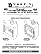
Fig. 32 Combustible side wall protection and hearth extension dimensions.
Minimum Wall Clearances
WITH
Noncombustible
Surround Facing
WITHOUT
Noncombustible
Surround Facing
Minimum Hearth Extension Dimensions
(for On-Site Construction)
G
H
G
J
Seal cracks
between the
fireplace
and hearth
extension with
noncombustible
material
Safety strips
must overlap
" minimum
May install
noncombustible
decorative
covering
OR .018" min.
sheet metal
Fireplace
Hearth
Combustible
Floor
Minimum
Insulation
Value "R":
4" Min.
Firebox
Opening
A - Min. clearance
to combustible
perpendicular wall
B - Min. clearance
to combustible
perpendicular wall when
using noncombustible wall shield*
Side
Wall
Side
Wall
F**
C**
E
E
D
4" Brick
(Example material)
Combustible material permitted within shaded area.
*
Noncombustible wall shield requires 1" CFM Corporation
EH2416 insulation (minimum R Value = 1.85) between
decorative noncombustible rigid covering and combustible wall.
Minimum height and width is 40" x 40".
**
Dimension/degree of angle will vary depending on thickness
of noncombustible surround facing.
4"
Shaded area starts
1/2" away from
edge of unit
A B C D E F G H J
SHR36 20" 12" 35° 42° 18" 14" 8" 16" 52"
(508 mm) (305 mm) (457 mm) (356 mm) (203 mm) (406 mm) (1321 mm)
SHR42A 22" 18" 32¹⁄₂° 39¹⁄₂° 18" 14" 12" 20" 66"
(559 mm) (457 mm) (457 mm) (356 mm) (305 mm) (508 mm) (1676 mm)
SHR48 28" 18" 26¹⁄₂° 33° 18" 14" 10" 24" 68"
(711 mm) (457 mm) (457 mm) (356 mm) (254 mm) (610 mm) (1227 mm)
SHR52 30" 20" 33¹⁄₂° 38¹⁄₂° 24" 20" 14" 24" 80"
(762 mm) (508 mm) (610 mm) (508 mm) (356 mm) (610 mm) (2032 mm)
FP1169
Ty
pe A floor
12/20/01 djt
Seal Cracks Between
Fireplace and Hearth
Extension with Non-
combustible Material
Noncombustible
Decorative Covering
May be Installed
or
.018" Minimum
Sheet Metal
Fireplace
Hearth
Lower Sur-
round
Majestic Safety
Strips Must be
Overlapped 1/2"
Min.
Minimum Insula-
tion Value R-3.28
(Refer Table 4)
Min. Thickness
(Refer to Table 4)
2¹⁄₂" Min.
Combustible
Floor
FP1169
Majestic Safety
Strips Must be
Overlapped 1/2"
Min.
Minimum Insulation
Value R-0.94
1/4" Min.
Thickness
Combustible
Floor
Noncombustible
Material 7⁷⁄₁₆" Max.
Thickness
Seal Cracks Between Fireplace and Hearth
Extension with Noncombustible Material
Noncombustible
Material
Lower
Surround
Fireplace
Hearth
FP1170
Fig. 33 Protection of adjacent combustible side walls and hearth extension dimensions.

19
SHR Series Woodburning Fireplaces
20001384
removed from gas line tube to repack space around the
pipe. Material should be inserted from outside of the
fireplace and packed tightly to totally seal between the
pipe and tube.
NOTE: Gas pipe should not come in contact with any
wood structures until it has reached a point at least
one (1) inch away from fireplace side.
NOTE: When installing an ANSI Z21.11.2 ventless appli-
ance, the finishing material used for the mantel must be
rated at 250°F or greater.
BTU input of a gas appliance installed in fireplace should
be rated less than 100,000 BTU/Hr.
Gas pipe installation is intended for connection to a deco-
rative gas appliance only when (1.) incorporating an auto-
matic shutoff device and (2.) complying with the Standard
for Decorative Gas Appliances for Installation in Vented
Fireplaces (ANSI Z21.60) or CSA draft requirements
for Gas-Fired Log Lighters for Woodburning Fireplaces
(Draft No. 4, August 1993).
Decorative gas appliance should be installed in accor-
dance with the National Fuel Gas Code, ANSI Z223.1/
NFPA 54 (latest edition).
CAUTION: WHEN USING DECORATIVE GAS
APPLIANCE, FLUE DAMPER MUST BE SET
IN FULLY OPEN POSITION. IF YOU HAVE
GLASS DOORS ON THE FIREPLACE, THEY
MUST ALSO BE FULLY OPENED.
WARNING: DO NOT OPERATE AN
UNVENTED GAS LOG SET IN THIS FIRE-
PLACE WITH THE CHIMNEY REMOVED.
WARNING: WHEN INSTALLING AN
UNVENTED GAS LOG SET, THE
CFM
CORPORATION MODEL AH3244BK OR
AH3244PB 4" ADJUSTABLE HOOD MUST BE
USED.
Installing Line for Gas Logs
CFM Corporation fireplaces are designed to accept a 1/2
inch gas line for installation of an approved gas appli-
ance. (CFM Corporation manufactures a wide variety of
gas logs for use in CFM Corporation fireplaces.)
Be sure to have the appliance installed in accordance
with building codes.
Gas connection may enter from either left or right side of
the fireplace.
Locate appropriate gas line in the outer casing of fire
-
place and remove insulation from gas line tube. (Fig. 36)
From inside the fireplace, locate the knockout on the fire
-
brick -- be sure you are on the appropriate or "gas line"
side of the fireplace. Using a flat bladed screwdriver or
small chisel and hammer, carefully tap around the knock-
out until it loosens and falls out.
Install 1/2 inch certified gas pipe through opening. After
gas pipe installation is complete, use insulation that was
FP1171
sealing detail
12/20/01 djt
Wall Covering
2 x 4 Header
- Do Not Notch at
Ledge Brackets
Fig. 22 or 23
Hearth Extension
Hearth
Extension Insulation
Molding used to
Fasten Hearth
Extension
in Place
Majestic Safety Strips Must
be Overlapped 1/2" Min.
Seal Crack Between
Fireplace and Hearth
Extension with
Noncombustible Material
FP1171
Fig. 34 Sealing detail.
FP1172
sealing detail 2
12/20/01 djt
2 x 4 Header
- Do Not Notch at
Ledge Brackets
Fig. 24
Wall Covering
Noncombustible
Decorative Facing
Seal All Cracks
Between Fireplace
Surround and Wall
Materials with
Noncombustible
Material
Noncombustible
Decorative Covering
Majestic Safety Strips Must
be Overlapped 1/2" Min.
Seal Crack Between Fire-
place and Hearth Exten-
sion with Noncombustible
Material
FP1172
Fig. 35 Sealing detail.
Hearth
Extension
1"
Min.
FP560SHR
SHR series
5/12/99 djt
1/2"
FP560SHR
Fig. 36 Gas line access.
Hole in Outer Casing
Gas Line
Tubing
Ceramic
Knockout
Hole in
Outer Casing
Supply Line
Repack Insulation
Ceramic Knockout
(both sides)
Only unvented gas log sets which have been found to comply with
the Standard for Unvented Room Heaters, ANSI Z21.11.2, are to be
installed in this fireplace.
If installing an unvented gas log set, refer to statement below:

20
SHR Series Woodburning Fireplace
20001384
1384 pts
replacement parts
5/27/99 djt
7/14/99 removed clips,added push nut
1
2
3
4
5
6
7
8
a
b
c
9
10
11
d
12
13
CFM Corporation reserves the right to make changes in design, materials, specifications, prices and discontinue colors and products at any time,
without notice.
SHR36/42A/48/52 Woodburning Fireplace
For units FH30R0, GH40R0, HH30R0, IH10R0
Ref. Description SHR36 SHR42A SHR48 SHR52
1. Damper Weld Assembly RP210 RP210 RP210 n/a
2. Damper Handle 20001418 20001418 20001418 20005322
3. Screen Rail 20001429 20006021 20001431 20005569
4. Screen Rod (two per fireplace) 7554181 7554199 20001428 20005790
5. Screen (two per fireplace) 7554295 20001723 20001723 20005278
6. Screen Pull (two per fireplace) 5584139 5584139 5584139 5584139
7. Push Nut (two per fireplace) 7512167 7512167 7512167 7512167
8a. Firebrick - Hearth 20001272 20005611 20001172 20005303
8b. Firebrick - Back 20004165 20005610 20004147 20005293
8c. Firebrick - Left Side 20004166 20005612 20004154 20005302
8d. Firebrick - Right Side 20004167 20005613 20004148 20005304
9. Firebrick Retainers (three per fireplace) 20001432 20001432 20001432 20001432
10. Basket Grate 20004203 20004203 20004311 20005433
11. O.S.A. Assy. 20003076 20003076 20003076 20005762
12. Damper Blade Assy n/a n/a n/a 20007536
13. Pivot Rod n/a n/a n/a 20005772
Page is loading ...
Page is loading ...
Page is loading ...
Page is loading ...
/