Page is loading ...

LBI-39128
ericssonzericssonz
Installation & Operation
EDACS
Power Monitor Unit

LBI-39128 CONTENTS
Copyright March 1995, Ericsson Inc.
2
TABLE OF CONTENTS
Page
INTRODUCTION....................................................................................................................................... 6
DESCRIPTION........................................................................................................................................... 6
APPLICATION NOTES............................................................................................................................. 7
VAX SITE CONTROLLER COMPUTER.......................................................................................... 7
APPLICATION SOFTWARE PROMS............................................................................................... 7
PERSONALITY PROMS .................................................................................................................... 7
INSTALLATION........................................................................................................................................ 8
SITE CONTROLLER HARDWARE................................................................................................... 8
SITE CONTROLLER SOFTWARE.................................................................................................... 8
Application Software PROMs....................................................................................................... 9
Personality PROMs....................................................................................................................... 9
PMU HARDWARE ............................................................................................................................. 9
A. Addition from No PMU............................................................................................................ 9
B. Upgrade from Old PMU........................................................................................................... 12
C. Adaptation from Old PMU ....................................................................................................... 13
INITIAL POWER-UP.......................................................................................................................... 14
PMU PROGRAMMING...................................................................................................................... 15
Terminal Setup.............................................................................................................................. 15
Software Initialization ................................................................................................................... 15
Time/Date/Password...................................................................................................................... 17
Antenna Mapping.......................................................................................................................... 18
POWER SENSOR CALIBRATION.................................................................................................... 19
Unidirectional Power Sensors ....................................................................................................... 19
Bi-directional Power Sensors ........................................................................................................ 20
FINAL CHECK.................................................................................................................................... 21
(Continued)
NOTICE
This Manual covers Ericsson and General Electric products manufactured and sold by Ericsson Inc.
NOTICE
Repairs to this equipment should be made only by an authorized service technician or facility designated by the supplier. Any
repairs, alterations or substitution of recommended parts made by the user to this equipment not approved by the
manufacturer could void the user’s authority to operate the equipment in addition to the manufacturer’s warranty.
NOTICE!
The software contained in this device is copyrighted by Ericsson Inc. Unpublished rights are reserved under the copyright
laws of the United States.
This manual is published by
Ericsson Inc.
, without any warranty. Improvements and changes to this manual necessitated by typographical errors,
inaccuracies of current information, or improvements to programs and/or equipment, may be made by
Ericsson Inc.
, at any time and without notice. Such
changes will be incorporated into new editions of this manual. No part of this manual may be reproduced or transmitted in any form or by any means,
electronic or mechanical, including photocopying and recording, for any purpose, without the express written permission of
Ericsson Inc.
NOTICE
This Manual covers Ericsson and General Electric products manufactured and sold by Ericsson Inc.
NOTICE
Repairs to this equipment should be made only by an authorized service technician or facility designated by the supplier. Any
repairs, alterations or substitution of recommended parts made by the user to this equipment not approved by the
manufacturer could void the user’s authority to operate the equipment in addition to the manufacturer’s warranty.
NOTICE!
The software contained in this device is copyrighted by Ericsson Inc. Unpublished rights are reserved under the copyright
laws of the United States.
This manual is published by
Ericsson Inc.
, without any warranty. Improvements and changes to this manual necessitated by typographical errors,
inaccuracies of current information, or improvements to programs and/or equipment, may be made by
Ericsson Inc.
, at any time and without notice. Such
changes will be incorporated into new editions of this manual. No part of this manual may be reproduced or transmitted in any form or by any means,
electronic or mechanical, including photocopying and recording, for any purpose, without the express written permission of
Ericsson Inc.

CONTENTS LBI-39128
3
TABLE OF CONTENTS (Cont.)
Page
OPERATION.............................................................................................................................................. 22
STARTUP............................................................................................................................................ 22
Polling Recovery........................................................................................................................... 22
EDACS Configuration Setup ........................................................................................................ 22
Polling Failure............................................................................................................................... 22
MONITOR........................................................................................................................................... 22
Power Sensor Monitoring.............................................................................................................. 22
Power Measurements .................................................................................................................... 23
SWR Calculations......................................................................................................................... 23
ALARMS............................................................................................................................................. 23
Alarm Reporting............................................................................................................................ 24
Excessive Alarms.......................................................................................................................... 24
PARAMETERS ................................................................................................................................... 25
Channel PMU Enable.................................................................................................................... 25
Site PMU Enable........................................................................................................................... 25
PMU Model .................................................................................................................................. 25
Transmitter Lower Alarm Limit.................................................................................................... 27
Transmitter Upper Alarm Limit .................................................................................................... 27
Antenna Lower Alarm Limit......................................................................................................... 27
Antenna Upper Alarm Limit ......................................................................................................... 27
SWR Upper Alarm Limit.............................................................................................................. 28
Antenna Mapping.......................................................................................................................... 28
ALARM LIMIT RE-CONFIGURATION ........................................................................................... 28
Alarm Limits As Installed............................................................................................................. 28
Transmitter Power Alarm Limits................................................................................................... 28
Antenna Power Alarm Limits........................................................................................................ 28
Antenna SWR Alarm Limit........................................................................................................... 29
MAINTENANCE........................................................................................................................................ 30
POWER SENSOR CALIBRATION.................................................................................................... 30
TIME AND DATE ADJUSTMENT.................................................................................................... 30
DIAGNOSTIC SCREENS................................................................................................................... 30
Alarm History Report Screen........................................................................................................ 30
Channel Monitor Screen................................................................................................................ 30
SOFTWARE UPDATES ..................................................................................................................... 32
ERASE ALL PROGRAMMING ......................................................................................................... 32
ALARM DELAY ADJUSTMENT...................................................................................................... 33
TROUBLESHOOTING....................................................................................................................... 34
GLOSSARY................................................................................................................................................ 36
PMU INTERCONNECT DIAGRAM - EDACS REPEATER CABINET ................................................. 37
PMU INTERCONNECT DIAGRAM - SITE CONTROLLER CABINET (Upgrade) .............................. 38

LBI-39128 FIGURES AND TABLES
4
LIST OF FIGURES AND TABLES
Page
Figure 1 - Location of PMU Components.................................................................................................... 6
Figure 2 - Card Layout for PDP Upgraded to VAX .................................................................................... 7
Figure 3 - Location of Fastener Screws on Computer.................................................................................. 8
Figure 4 - Location of PROM Card in Computer ........................................................................................ 8
Figure 5 - Location of PROM Card in Older Computer.............................................................................. 8
Figure 6 - Location of PROMs on PROM Card .......................................................................................... 8
Figure 7 - Application Software PROM Label ............................................................................................ 9
Figure 8 - Personality PROM Label ............................................................................................................ 9
Figure 9 - Antenna Power Sensor Connections............................................................................................ 11
Figure 10 - Connections for Addition from No PMU.................................................................................. 12
Figure 11 - Connections for Upgrade from Old PMU................................................................................. 13
Figure 12 - Connections for Adaptation from Old PMU ............................................................................. 14
Figure 13 - DB-25 Terminal Connections ................................................................................................... 15
Figure 14 - DB-9 Terminal Connections ..................................................................................................... 15
Figure 15 - Operation Select Menu (Main Menu) ....................................................................................... 16
Figure 16 - Setup Selection Menu ............................................................................................................... 16
Figure 17 - Site Data #1 Screen................................................................................................................... 17
Figure 18 - Analog Input Channel Screen.................................................................................................... 18
Figure 19 - Analog Input Channel Screen Showing Antenna Channel Parameter ....................................... 19
Figure 20 - Unidirectional Power Sensor Calibration Screw....................................................................... 19
Figure 21 - Bi-directional Power Sensor Calibration Screws ...................................................................... 20
Figure 22 - Analog Pseudo Channel Screen ................................................................................................ 29
Figure 23 - Report Selection Menu.............................................................................................................. 31
Figure 24 - Alarm History Report Screen.................................................................................................... 31
Figure 25 - Channel Monitor Screen............................................................................................................ 31
Figure 26 - Location of PMU Software....................................................................................................... 32
Figure 27 - Location of DIP Switches ......................................................................................................... 33
Table 1 - Selection of Installation Procedure............................................................................................... 9
Table 2 - Parts for Addition from No PMU................................................................................................. 10
Table 3 - Parts for Upgrade from Old PMU................................................................................................ 12
Table 4 - Parts for Adaptation from Old PMU............................................................................................ 13
Table 5 - Terminal Communications Protocol............................................................................................. 15
Table 6 - Power Sensor Voltage-to-Power Conversion Table..................................................................... 21
Table 7 - PMU Option Parameters .............................................................................................................. 26
Table 8 - SWR Upper Limit ........................................................................................................................ 30
Table 9 - Channel Numbers for Channel Monitor Screen............................................................................ 32
Table 10 - Troubleshooting Symptoms........................................................................................................ 34

SPECIFICATIONS LBI-39128
5
SPECIFICATIONS
PMU:
Mechanical:
Width ............................................................19 in. (482.6 mm)
Height............................................................3.5 in. (88.9 mm)
Depth.............................................................6 in. (152.4 mm)
Weight...........................................................< 5 lb. (2.27 kg)
Environmental:
Temperature Range.......................................0° to 60° C (32° to 140° F)
Relative Humidity.........................................0 to 95%
Power Requirements:
External.........................................................12 Watts (max.) at 12 Vdc (nominal)
RAM Battery Life .........................................3 years
Power Sensors:
19C336861P2 - Unidirectional
Frequency Range...........................................450 to 1000 MHz
Maximum Power...........................................1000 Watts
19C336861P3 - Bi-directional
Frequency Range...........................................450 to 1000 MHz
Maximum Power...........................................1000 Watts
19C336861P4 - Bi-directional
Frequency Range...........................................66 to 325 MHz
Maximum Power...........................................1000 Watts
Data Interfaces:
Site Controller Computer:
Baud Rate......................................................9600
Data Bits........................................................8
Parity Bit.......................................................None
Stop Bit.........................................................1
RS-232 CRT Terminal (or PC):
Baud Rate......................................................9600
Data Bits........................................................8
Parity Bit.......................................................None
Stop Bit.........................................................1

6
INTRODUCTION
This manual describes the installation and operation of
the Decibel Products DB8860-based PMU (Power Monitor
Unit) for non-simulcast EDACS (Enhanced Digital Access
Communications System) repeater sites that use a VAX
computer for the Site Controller. This manual covers only
those features of the Decibel Products DB8860 that are
required for this application.
The user must provide an RS232 CRT terminal (or PC
with terminal emulation software) for installation and
maintenance.
DESCRIPTION
The PMU (Power Monitor Unit) is used to quickly
identify damaged transmitters, transmit combiners, transmit
antennas, and connecting cables so that the equipment can
be quickly removed from service and repaired. The PMU is
a microprocessor-driven power monitoring and reporting
device that receives power measurements from the power
sensors, receives monitoring instructions from the Site
Controller computer, and reports alarm conditions back to
the Site Controller computer.
A unidirectional power sensor is placed at the output of
each transmitter to send forward power measurements to the
PMU. A bi-directional power sensor is placed at the output
of each transmitter combiner to send forward and reflected
power measurements to the PMU.
The Site Controller computer tells the PMU which
power sensors to monitor and when, by telling the PMU
when each transmitter is keyed and unkeyed.
The PMU reports an alarm for a specific transmitter
when the output power measurement for that transmitter
exceeds the upper or lower power limit. The Site Controller
computer then takes that transmitter out of service.
The PMU reports an alarm for a specific antenna
number when the input power measurement for that antenna
exceeds the upper or lower power limit, or the SWR
calculation exceeds the upper limit.
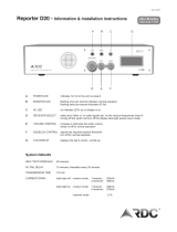
Figure 1 shows the locations of the PMU-related
components in a standard 20-channel EDACS installation
after the PMU option has been installed. Each standard
EDACS repeater cabinet includes the unidirectional power
sensors, power sensor cables, power sensor module, and
cabinet interconnect cable. The cable between the Site
Controller computer and the PMU, the cables between the
PMU and the Power Sensor interface module, and the Power
Sensor interface module all come with the PMU. The bi-
directional (antenna) power sensor(s) are ordered separately.
If the PMU option is to be installed in an older EDACS
site, you may need some additional material to update or
adapt to the older equipment (see the Installation section in
this manual for details).
Antenna #1
Xmtr
#12
Antenna #2
Controller
Xmtr
#11
Xmtr
#10
Xmtr
#9
Xmtr
#8
Xmtr
#7
Xmtr
#6
Xmtr
#5
Xmtr
#4
Xmtr
#3
Xmtr
#2
Xmtr
#1
Xmtr
#15
Xmtr
#14
Xmtr
#13
Xmtr
#18
Xmtr
#17
Xmtr
#16
Xmtr
#20
Xmtr
#19
Transmitter Combiner #2Transmitter Combiner #1
Power
Power Sensor
Module
Unidirectional
Power
Sensor
Power
Bi-directional
Sensor
Unit
Monitor
Computer
Site
Power Sensor
Cable
Transmitter
Cabinet
Interconnect
Cable
Antenna Power Sensor Cable
Interface Module
Interface
Figure 1 - Location of PMU Components

APPLICATION NOTES LBI-3912
8
7
APPLICATION NOTES
VAX SITE CONTROLLER COMPUTER
Make sure that the Site Controller computer, at the
location where this PMU is to be installed, is a VAX model
or a PDP model that has been upgraded to a VAX model. To
determine if a PDP model has been upgraded internally to a
VAX model, you must look inside the PDP system chassis
and see which cards are installed. PDP models that have
been upgraded to a VAX model will have their cards
arranged in the card cage as shown in Figure 2.
KA620-BA
MS630-BB
MRV11-D H3656-00
CQ1610#1
CQ1610#2
EMPTY
EMPTY
EMPTY
Figure 2 - Card Layout for PDP Upgraded to VAX
APPLICATION SOFTWARE PROMS
The Site Controller computer’s Application Software
PROMs must be marked 344A3265Gx, where x = 6 or
higher. (Application Software PROMs with x = 5 or lower
will not work for the new PMU.) If new Application
Software PROMs are needed, they should be ordered when
ordering the new PMU.
PERSONALITY PROMS
The Site Controller computer’s Personality PROMs
must be replaced, even if the system currently has an old
PMU and a System Manager. New Personality PROMs
should be ordered when ordering the new PMU.
When ordering new Personality PROMs, you must give
the correct information for the following four PMU
parameters (don’t assume that the person taking the order
will know what you want, need, or the recommendations
given here):
•
PMU Enable
- This parameter set (mask) defines
(for each channel) if that channel number is to be
monitored by the PMU. This parameter is not
System Manager re-configurable and therefore all
equipped channels must be enabled. It is
recommended that all 20 channels be enabled
(equipped or not).
•
Power Monitor Unit
- This parameter can be set
to “Off” (if you want the PMU option disabled) or
“On” (if you want the PMU option enabled). This
parameter is System Manager re-configurable, but
must be set to “On” if the site is being operated
without a System Manager. It is recommended that
this parameter be set to “On”, even if the site is
being operated with a System Manager.
•
PMU Model
- This parameter can be set to “Old-
8843” (PMU protocol set to 2400 Baud for Decibel
Products DB8843 based old PMU) or “New-8860”
(PMU protocol set to 9600 Baud for Decibel
Products DB8860 based new PMU). This
parameter is not System Manager re-configurable
and therefore must be set to “New-8860”.
•
PMU Power Levels
- This parameter defines the
lower power level limit for all transmitters (one
limit is applied to all). This parameter is System
Manager re-configurable, but must be set to some
power level lower than rated power if the site is
being operated without a System Manager. It is
recommended that this parameter be set to 50% of
the rated power, even if the site is being operated
with a System Manager.
If this PMU option is being installed in the field,
these Personality PROMs must be changed, even
if the system currently has the old PMU option
and a System Manager.
NOTE

LBI-39128 INSTALLATION
8
INSTALLATION
SITE CONTROLLER HARDWARE
Verify that the Site Controller computer is a VAX
model, or a PDP model that has been upgraded to a VAX
model (see the VAX Site Controller heading in the
Applications Notes section). If you find that the Site
Controller computer is a PDP model, upgrade kits are
available through Ericsson Service Parts. Alternatively, the
PDP model may be replaced with the current 19A149302P9
VAX model.
SITE CONTROLLER SOFTWARE
The Site Controller computer contains a set of 14
Application Software PROMs and a set of two Personality
PROMs. Both sets are located on the PROM card. Access to
the PROM card in the latest VAX version of the Site
Controller computer is through the back using the following
procedure:
1. Turn off the Site Controller computer.
2. Loosen the two fastener screws holding the back
panel to the chassis (see Figure 3).
2345678
15
28293031
1
0 SM
14 13 12 11 10 9
27 26 25 24
20212223
19 18 17 16
Fastener
Screws
Figure 3 - Location of Fastener Screws on Computer
3. Rotate the back panel down and out of the way (be
careful not to damage the ribbon cables).
PROM Card
Figure 4 - Location of PROM Card in Computer
4. Remove the PROM Card (see Figure 4) by pulling
on the two tabs fastened to the front edge of the
card. (Observe standard handling practices for
static sensitive components.)
Access to the PROM card in previous VAX versions
and older PDP versions that were upgraded to a VAX
version is through the top using the following procedure:
1. Turn off the Site Controller computer.
2. Pull the Site Controller computer chassis all the
way forward on its slide-out track.
3. Pull up the top cover and the attached card cage.
4. Remove the PROM Card (see Figure 5) by pulling
on the two tabs fastened to the front edge of the
card. (This is a three-handed operation - observe
standard handling practices for static sensitive
components.)
PROM Card
Figure 5 - Location of PROM Card in Older Computer
03 04
0201
0807
0605
09 10
11 12
13 14
01 02
Personality
PROMs
01-02
Software
Application
PROMs
01-14
Figure 6 - Location of PROMs on PROM Card

INSTALLATION LBI-39128
9
The location of the Application Software and
Personality PROMs on the PROM card is shown in Figure
6. When replacing PROMs, be sure to get each new PROM
in the correct location, and with the notched end as shown.
Be especially careful of location numbers 01 and 02 since
these numbers are used for both sets of PROMs.
Application Software PROMs
Check the revision number marked on the Application
Software PROMs. Each of the 14 Application Software
PROMs must be marked 344A3265Gx, where x = 6 or
higher. (Application Software with x = 5 or lower will not
work for the new PMU option.) Figure 7 shows where to
find the software revision number and the PROM location
number on a typical Application Software PROM label.
Replace all 14 Application Software PROMs if required.
344A3265G6
VAX SITE CTRLR
EDACS
1994 BY ERICSSON GE
C
01
PROM Location
Software Revision
Figure 7 - Application Software PROM Label
Personality PROMs
Replace the two Personality PROMs, even if a PMU
was previously installed with this Site Controller computer.
Figure 8 shows a typical Personality PROM label. (See the
Application Notes section if you need to order new
Personality PROMs.)
SER#: 12345678
SITE CONTROLLER
EDACS
PERSONALITY
01
PROM Location
Serial Number
Figure 8 - Personality PROM Label
PMU HARDWARE
There are three procedures for the installation of the
PMU hardware. The procedure you should use will depend
upon whether or not the Site Controller cabinet presently
contains EDACS Interface Panels and/or an old PMU. The
EDACS Interface Panels are located in the back of the
cabinet, near the top. Each panel consists of a 5 1/4 inch X
19 inch frame containing one or more interface modules
(boards with connectors). Use Table 1 to select the right
PMU hardware installation procedure for your system.
Table 1 - Selection of Installation Procedure
INTERFACE
PANEL
OLD
PMU
HARDWARE INSTALLATION
PROCEDURE
Yes No A. Addition from No PMU
Yes B. Upgrade from Old PMU
No Yes C. Adaptation from Old PMU
The table and the procedures assume that the equipment
that presently exists in the Site Controller cabinet is one of
the previous standard configurations. Regardless of which
procedure is used, it is very important to know exactly what
equipment presently exists, review what has to be done, and
be sure you have all the parts you will need before
you start
the installation.
A. Addition from No PMU
Use this procedure only if your Site Controller cabinet
has EDACS Interface panels, but doesn’t have a PMU.
This procedure consists of adding the PMU, Power
Monitor interface module, cables between the PMU and the
Power Monitor interface module, cable between the PMU
and the Site Controller computer, and DC power wires to the
PMU, all in the Site Controller cabinet. It also consists of
adding the antenna power sensor(s) in the RF Equipment
cabinet(s), and the antenna power sensor cables between the
antenna power sensor(s) in the RF Equipment cabinet(s) and
the Power Monitor interface module in the Site Controller
cabinet.

LBI-39128 INSTALLATION
10
Parts Required
Before you start this procedure, be sure you have all the
parts on hand. The parts for this procedure are shown in
Table 2.
Table 2 - Parts for Addition from No PMU
QTY PART # DESCRIPTION
1 19D903880P100
or
19D903880P101
Cable - DILOG Panel to
PMU
Cable - Site Controller
computer to PMU
1 350A1380P1 Decibel Products DB8860-
based PMU Unit
1 188D6466P1 Cable - PMU to Power
Sensor interface module
5 188D6466P2 Cable - PMU to Power
Sensor interface module
1 19C852632G1 Power Sensor interface
module
1 19C852677P1 Cable - Power Sensor
interface module to Antenna
power sensor(s)
1 or
2
19C336861P3
or
19C336861P4
Antenna power sensor (450
- 1000 MHz)
Antenna power sensor (66 -
325 MHz)
Procedure
The following steps involve equipment in the Site
Controller cabinet, except as noted:
1. Turn off the main 12V power supply for the cabinet.
2. Replace the 5 1/4 inch blank panel just above the
Downlink GETC (called Trunking Card in some older
installations) with the PMU. There will be a half rack
unit space (7/8 inch) both above and below the PMU.
3. Connect the #18 red wire from the terminal on the back
of the PMU labeled “+”, to TB10-7 on the back of the
Downlink GETC shelf.
4. Connect the #18 black wire from the terminal on the
back of the PMU labeled “–”, to TB10-6 on the back of
the Downlink GETC shelf.
5. Mount the new 19C852632G1 Power Sensor interface
module on the left-hand end of the upper EDACS
Interface Panel in the upper rear of the cabinet, using
the four thread forming screws provided with it. (You
will need a T15 Torx-head screwdriver.) If an old
Power Sensor interface module is mounted there,
replace it with the new 19C852632G1 interface module.
This interface module contains two 19C852379G1
Channel Termination Boards, each containing 12
shorting jumpers. The board plugged into J1 is used to
short any unused power sensor circuit for Transmitter
channels #1 through #12. The board plugged into J2 is
used to short any unused power sensor circuit for
Transmitter channels #11 through #20.
6. Remove the 19C852379G1 Channel Termination Board
from J1 on the Power Sensor interface module (installed
in step 5), and connect a 25-pair cabinet interconnect
cable in its place. Connect the other end of the 25-pair
cabinet interconnect cable to J14 or J15 on the Power
Sensor interface module in the EDACS Repeater
cabinet containing the transmitter for channel #1). If the
two cabinets are next to each other in the same row, use
a 5-ft 19D903880P120 cable. If the two cabinets are
across from each other in different rows, use a 15-ft
19D903880P121 cable.
7. Starting with the cabinet containing the transmitter for
channel #1, follow the daisy chain of 25-pair cabinet
interconnect cables connected to J14 and J15 on the
Power Sensor interface module in each EDACS
Repeater cabinet until an empty J14 or J15 connector is
found. Plug the 19C852379G1 Channel Termination
Board (removed in the previous step) into this empty
connector.
8. Remove the shorting jumper for each transmitter
channel # equipped with a power sensor (P#
corresponds to transmitter channel #).
Note that there is a shorting jumper for transmitter
channels #11 and #12 on each of the 19C852379G1
Channel Termination Boards. Therefore, if transmitter
channel #11 or #12 is equipped with a power sensor, a
jumper must be removed from each of the two channel
termination boards.
9. If the system does not have any additional EDACS
Repeater cabinets not included in the daisy chain in the
previous step, go to step 11.
If the system has additional EDACS Repeater cabinets
not included in the daisy chain in the previous step,
remove the 19C852379G1 Channel Termination Board
from J2 on the Power Sensor interface module (installed
in step 5), and connect a 25-pair cabinet interconnect
cable in its place. Connect the other end of the 25-pair
cabinet interconnect cable to J14 or J15 on the Power

INSTALLATION LBI-39128
11
Sensor interface module in the EDACS Repeater
cabinet containing the transmitter for channel #11 or
#13). If the two cabinets are next to each other in the
same row, use a 5-ft 19D903880P120 cable. If the two
cabinets are across from each other in different rows,
use a 15-ft 19D903880P121 cable.
10. Starting with the cabinet containing the transmitter for
channel #11 or #13, follow the daisy chain of 25-pair
cabinet interconnect cables connected to J14 and J15 on
the Power Sensor interface module in each EDACS
Repeater cabinet until an empty J14 or J15 connector is
found. Plug the 19C852379G1 Channel Termination
Board (removed in the previous step) into this empty
connector.
11. Remove a shorting jumper in the 19C852379G1
Channel Termination Board for each transmitter
channel # equipped with a power sensor (P# plus 12
corresponds to transmitter channel #). Note that the P#
corresponds to a different transmitter channel # in this
case.
Note that there is a shorting jumper for transmitter
channels #11 and #12 on each of the 19C852379G1
Channel Termination Boards. Therefore, if transmitter
channel #11 or #12 is equipped with a power sensor, a
jumper must be removed from each of the two channel
termination boards.
12. Connect the five new 188D6466P2 cables from J3
through J7 on the Power Sensor interface module in the
upper EDACS Interface Panel, to Port 1 through Port 5
respectively on the back of the PMU.
13. Connect the new 188D6466P1 cable from J8 on the
Power Sensor interface module in the upper EDACS
Interface Panel, to PORT 7 on the back of the PMU.
14. If the Site Controller computer has modular RJ11-8
connectors on its back panel, connect the new
19D903880P101 cable from the right-hand VDT
Interface on the back of the PMU, to Port 29 on the
back of the Site Controller computer.
If the Site Controller computer does not have modular
RJ11-8 connectors on its back panel, connect the new
19D903880P100 cable from the right-hand VDT
Interface on the back of the PMU to connector #13 on
the right-hand (B) DILOG panel (above the Site
Controller computer).
15. Install the 19C336861P3 or P4 antenna power sensor(s)
at the output of the transmitter combiner(s) in the RF
Equipment cabinet(s).
16. Install the 19C852677P1 antenna power sensor cable
from J9 on the Power Sensor interface module in the
Site Controller cabinet, to the antenna power sensor(s)
in the RF equipment cabinet(s) as shown in Figure 9. If
the system has only one antenna, tack solder a jumper
(tip to shield) on each of the unused phono plugs to
short the forward and reflected power sensor circuits for
antenna #2.
1
6
2
3
4
7
8
9
High
Ground
Forward
Forward
Reflected
Reflected
Antenna #1
Antenna #2
High
Ground
High
Ground
High
Ground
DB-9 (F)
J9
DB-9 ( M)
POWER SENSOR
19C852632G1
Antenna Power Sensor Cable
Antenna Power Sensors
to Interface Module
Figure 9 - Antenna Power Sensor Connections
17. Double check the installation using the interconnection
diagram shown in Figure 10.
18. Set the power switch on the back of the PMU to the
“Off” position.
19. Turn on the main 12V power supply for the cabinet.

LBI-39128 INSTALLATION
12
J1 J2
J3
J4
J5
J6
J7
J8J9
188D6466P2 Cables (5 Each)
PORT 7 PORT 5
188D6466P1 Cable
PORT 8 PORT 6
Daisy Chain Cable to Power Sensors for Transmitter Channels 1 - 12
Daisy Chain Cable to Power Sensors for Transmitter Channels 11 - 20
Antenna Power Sensor Cable to Power Sensors for Antennas 1 & 2
19C852632G1 POWER SENSOR INTERFACE MODULE
POWER MONITOR UNIT
PORT 1PORT 4 PORT 2PORT 3
#18 Red
#18 Black
Terminal
Connection
SITE CONTROLLER
Use 19D903880P101 Cable If
112
6
7
Port 29
COMPUTER
DILOG DILOG
Connecting to DILOG Panel
13B
Use 19D903880P100 Cable If
0511 0511AB
Connecting to Site Controller Computer
Programming
VDT Interfaces
DOWNLINK GETC
(TRUNKING CARD)
Figure 10 - Connections for Addition from No PMU
B. Upgrade from Old PMU
Use this procedure only if your Site Controller cabinet
has EDACS Interface panels and an old PMU.
This procedure consists of upgrading the Site Controller
by replacing the old PMU, replacing the old Power Sensor
interface module, and replacing the cables between them.
Parts Required
Before you start this procedure, be sure you have all the
parts on hand. The parts for this procedure are shown in
Table 3.
Table 3 - Parts for Upgrade from Old PMU
QTY PART # DESCRIPTION
1 350A1380P1 Decibel Products DB8860-
based PMU Unit
1 188D6466P1 Cable - PMU to Power
Sensor interface module
5 188D6466P2 Cable - PMU to Power
Sensor interface module
1 19C852632G1 Power Sensor interface
module
Procedure
The following steps involve equipment in the Site
Controller cabinet only:
1. Turn off the main 12V power supply for the cabinet.
2. Mark “+” on the wire going to the screw terminal
marked “+” on the back of the old PMU. Then
disconnect this wire at the PMU end.
3. Mark “–” on the wire going to the screw terminal
marked “–” on the back of the old PMU. Then
disconnect this wire at the PMU end.
4. Mark “RS-232” on the cable going to the DB-25
connector marked “RS-232” on the back of the old
PMU. Then disconnect this cable at the PMU end.
5. Disconnect any cables going to the connectors marked
“Antennas 1-4”, “Transmitters 1-9”, “Transmitters 10-
18”, and “Transmitters 19-20” on the back of the old
PMU. (There is no need to label these cables since they
will not be used with the new PMU.)
6. Replace the old PMU with the new PMU. There will be
a half rack unit space (7/8 inch) both above and below
the new PMU.
7. Connect the existing wire labeled “+” in step 2 to the
terminal labeled “+” on the back of the new PMU.
8. Connect the existing wire labeled “–” in step 3 to the
terminal labeled “–” on the back of the new PMU.
9. Connect the existing cable labeled “RS232” in step 4 to
the right-hand VDT interface on the back of the new
PMU (see Figure 7).
10. Find the Power Sensor interface module mounted in the
left end of the upper EDACS Interface Panel in the
upper rear of the cabinet. If a cable is connected to the

INSTALLATION LBI-39128
13
Power Sensor interface module connector marked “J1”,
label the cable “J1” and disconnect it from the Power
Sensor interface module.
11. If a cable (or an existing 19C852379G1 Channel
Termination Board) is connected to the Power Sensor
interface module connector marked “J2”, label the cable
(or board) “J2” and disconnect it at the Power Sensor
interface module.
12. Find the cables (or group of cables) connected to the
Power Sensor interface module connectors marked “J6”
and “J7”, determine which cable (or group of cables)
goes to some point outside the cabinet, label this cable
(or group of cables) “J9” (the connector number on the
new Power Sensor interface module is different), and
disconnect this cable (or group of cables) at the Power
Sensor interface module.
13. Remove the old 19C852213G1 Power Sensor interface
module and all cables still connected to it (all cables
still connected to it should have been disconnected at
their other end in step #5).
14. Mount the new 19C852632G1 Power Sensor interface
module in the space vacated by the old module.
15. Connect the existing cables (or board) labeled “J1”,
“J2”, and “J9” in steps 10-12 to the connectors marked
“J1”, “J2”, and “J9” respectively on the new Power
Sensor interface module.
16. Connect the 5 new 188D6466P2 cables from J3 through
J7 on the new Power Sensor interface module to Port 1
through Port 5, respectively, on the back of the new
PMU.
17. Connect the new 188D6466P1 cable from J8 on the
new Power Sensor interface module to Port 7 on the
back of the new PMU (skip Port 6).
18. Double check the installation using the interconnection
diagram shown in Figure 11.
19. Set the power switch on the back of the PMU to the
“Off” position.
20. Turn on the main 12V power supply for the cabinet.
C. Adaptation from Old PMU
Use this procedure only if your Site Controller cabinet
doesn’t have EDACS Interface panels, but does have an old
PMU.
J1 J2
J3
J4
J5
J6
J7
J8J9
188D6466P2 Cables (5 Each)
PORT 7 PORT 5
188D6466P1 Cable
PORT 8 PORT 6
Daisy Chain Cable to Power Sensors for Transmitter Channels 1 - 12
Daisy Chain Cable to Power Sensors for Transmitter Channels 11 - 20
Antenna Power Sensor Cable to Power Sensors for Antennas 1 & 2
19C852632G1 POWER SENSOR INTERFACE MODULE
POWER MONITOR UNIT
PORT 1PORT 4 PORT 2PORT 3
#18 Red
#18 Black
Terminal
Connection
DOWNLINK GETC
112
6
7
Existing Cable To Site Controller Computer
Programming
VDT Interfaces
Figure 11 - Connections for Upgrade from Old PMU
This procedure consists of replacing the old PMU with
the new PMU, adding an adapter cable between the existing
transmitter power sensor cables and the new PMU, and
adding an adapter cable between the existing antenna power
sensor cable and the new PMU. The existing RS232 data
link to the Site Controller computer and the two DC power
wires can be re-connected directly to the new PMU. This
procedure upgrades the system to the extent that it adds the
new PMU, but uses adapter cables instead of upgrading to
the EDACS Interface Panel configuration.
Parts Required
Before you start this procedure, be sure you have all the
parts on hand. The parts for this procedure are shown in
Table 4.
Table 4 - Parts for Adaptation from Old PMU
QTY PART # DESCRIPTION
1 350A1380P1 Decibel Products DB8860-
based PMU Unit
1 188D6451P1 Adapter Cable - Transmitter
power sensor circuits
1 188D6496P1 Adapter Cable - Antenna
power sensor circuits

LBI-39128 INSTALLATION
14
Procedure
The following steps involve equipment in the Site
Controller cabinet, except as noted:
1. Mark the cables and wires going to the old PMU as
follows:
• Mark “Antennas 1-4” on the cable going to the DB-
15 connector on the back of old PMU marked
“Antennas 1-4”.
• Mark “Transmitters 1-9” on the cable going to the
DB-37 connector on the back of the old PMU
marked “Transmitters 1-9”.
• Mark “Transmitters 10-18” on the cable going to
the DB-37 connector on the back of the old PMU
marked “Transmitters 10-18”.
• Mark “Transmitters 19-20” on the cable going to
the DB-25 connector on the back of the old PMU
marked “Transmitters 19-20”.
• Mark “RS-232” on the cable going to the DB-25
connector on the back of the old PMU marked
“RS-232”.
• Mark “+” on the wire going to the screw terminal
marked “+”.
• Mark “–” on the wire going to the screw terminal
marked “–”.
2. Turn off the main 12V power supply for the cabinet.
3. Disconnect the cables and wires from the old PMU.
4. Replace the old PMU with the new PMU. There will be
a half rack unit space (7/8 inch) both above and below
the PMU.
5. Connect the 188D6451P1 adapter cable as follows:
• Connect the two DB-37 connectors on the adapter
cable marked “P2” and “P3” to the existing cables
(disconnected from the old PMU) marked
“Transmitters 1-9” and “Transmitters 10-18”
respectively.
• Connect the single DB-25 connector on one end of
the adapter cable marked “P4” to the existing cable
(disconnected from the old PMU) marked
“Transmitters 19-20”.
• Connect the five DB-25 connectors on the other
end of the adapter cable marked “P5”, “P6”, “P7”,
“P8”, and “P9” to Port 1 through Port 5
respectively on the back of the new PMU.
6. Connect the 188D6496P1 adapter cable as follows:
• Connect the DB-15 connector on the adapter cable
marked “P2” to the existing cable (disconnected
from the old PMU) marked “Antennas 1-4”.
• Connect the DB-25 connector on the adapter cable
marked “P3” to Port 7 on the back of the new
PMU.
7. Connect the existing cable (disconnected from the old
PMU) marked “RS-232” to the right VDT Interface
connector on the back of the new PMU.
8. Connect the existing wires (disconnected from the old
PMU) marked “+” and “–” to the screw terminals on the
back of the new PMU marked “+” and “–” respectively.
9. Double check the installation using the interconnection
diagram shown in Figure 12.
PORT 7 PORT 5PORT 8 PORT 6
POWER MONITOR UNIT
PORT 1PORT 4 PORT 2PORT 3
Terminal
Connection
Transmitters 1-9
Transmitters 10-18
Transmitters 19-20
Antennas 1-4
188D6451P1 Adapter Cable
P2
P3
P4
P5P6P7P8 P9
+
_
RS-232
Programming
188D6496P1 Adapter Cable
P2
P3
VDT Interfaces
Figure 12 - Connections for Adaptation from Old PMU
10. Set the power switch on the back of the PMU to the
“Off” position.
11. Turn on the main 12V power supply for the cabinet.
INITIAL POWER-UP
After the PMU equipment has been mounted and
checked, you are ready for the initial power-up of the PMU.
1. Temporarily disconnect the data link cable to the Site
Controller computer from the right-hand VDT Interface

INSTALLATION LBI-39128
15
on the back of the PMU (this cable will be re-connected
later in the installation).
2. Switch the On/Off switch on the back of the PMU to the
“On” position.
3. Verify that the “PWR” indicator on the front panel of
the PMU stays on continuously.
4. Verify that the three other indicators on the front panel
of the PMU are flashing in a repeating sequence. The
“MUX” indicator should flash once every 250
milliseconds; first by itself, next with the “DATA”
indicator, and then with the “ALARM” indicator.
PMU PROGRAMMING
The PMU’s operational program will use the factory
default values for its operational parameters unless re-
configured by the user. The user-configurable parameters
may be re-configured through the use of an RS232 CRT
terminal (or PC with terminal emulation software) connected
to the PMU.
Changing parameters not covered in this
manual may lead to unsatisfactory operation of
the PMU option.
CAUTION
Terminal Setup
The following initial steps are required to set up the
terminal and access the PMU.
1. Connect the RS232 CRT terminal to the left-hand VDT
Interface connector on the back of the PMU (see Figure
12). (DO NOT plug into the front of the PMU.) If the
RS232 CRT terminal has a male DB-25 port, connect
per Figure 13. If the terminal has a male DB-9 port,
connect per Figure 14.
DO NOT plug the RS232 CRT terminal into the
front panel of the PMU (damage to terminal
may result). This connnector is for another
device in another application.
CAUTION
22
33
Ground
Tx Data
Rx Data
Ground
Rx Data
Tx Data
55
DB-25 (F)DB-25 (M) DB-25 (M)DB-25 (F)
PMURS232 CRT Terminal
(or PC COM Port)
11
Null Modem Cable
4
4
6
7
2020
6
7
RTSRTS
CTS CTS
DSRDSR
DTRDTR
Left VDT Interface
Figure 13 - DB-25 Terminal Connections
22
33
Ground
Tx Data
Rx Data
Ground
Rx Data
Tx Data
Left VDT Interface
55
DB-25 (F)DB-9 (M) DB-25 (M)DB-9 (F)
PMURS232 CRT Terminal
11
Null Modem Cable
4
4
6
7
209
6
7
RTS
RTS
CTS
CTS
DSRDSR
DTR
DTR
8
(or PC COM Port)
Figure 14 - DB-9 Terminal Connections
2. Turn the terminal on and set the communications
protocol per Table 5.
Table 5 - Terminal Communications Protocol
PARAMETER VALUE
Baud Rate 9600 BPS
Data Bits 8
Parity None
Stop Bits 1
3. Press the Enter key one or more times until the
“Disconnected - Hit Any Key To Connect” prompt
appears on the terminal:
Software Initialization
Before you attempt to program any PMU parameters,
all parameters should be returned to the factory default
values. The following procedure is used to initialize the
PMU with its factory defaults:

LBI-39128 INSTALLATION
16
4. Type 8860 and press the Enter key. The Operation
Select Menu should then appear on the terminal as
shown in Figure 15 (revision # and date may be
different). If the PMU does not respond to this entry,
the password may have been re-configured from its
factory default value. See the Erase All Programming
heading in the Maintenance section for the procedure to
return all parameters to the factory default values,
including returning the password to 8860.
5. With the Operational Select Menu shown on the
terminal, type 4 (for item #4 - Setup) and press the
Enter key. The Setup Selection Menu should then
appear on the terminal as shown in Figure 16.
6. With the Setup Selection Menu shown on the terminal,
type 10 (for item #10 - Erase All Programming) and
press the Enter key.
7. At the “Enter Y to Continue, Any Other Character to
Abort:” prompt (after the warning message), type Y and
press the Enter key.
8. At the “Enter Site Password” prompt, type 8860 and
press the Enter key.
9. At the “Enter Site ID” prompt, type 1234 and press the
Enter key. You will be given a 4-second countdown and
then a flashing “Sentry Initialized” message.
10. Finally the Setup Selection Menu should appear on the
terminal.
SENTRY 8860 COPYRIGHT 1987-1994 DECIBEL PRODUCTS
PATENT 4,823,280
OPERATION SELECT MENU SENTRY PMU REV 8.6 12/07/94
1. DISCONNECT
2. REPORTS
3. MANUAL CONTROL
4. SETUP
5. HARDWARE STATUS
6. SOFTWARE STATUS
7. RESET ***WARNING - FOR EMERGENCY ONLY***
ENTER SELECTION:
Figure 15 - Operation Select Menu (Main Menu)
SETUP SELECTION MENU
1. RETURN TO OPERATION SELECT MENU
2. SITE DATA #1
3. SITE DATA #2
4. ANALOG INPUT CHANNEL
5. DIGITAL INPUT CHANNEL
6. ANALOG PSEUDO CHANNEL
7. DIGITAL PSEUDO CHANNEL
8. RELAY OUTPUTS
9. INPUT CONVERSION TABLE
10. ERASE ALL PROGRAMMING
11. db TEST CONFIGURATION
12. db TOWER LIGHTS CONFIGURATION
ENTER SELECTION: _
Figure 16 - Setup Selection Menu

INSTALLATION LBI-39128
17
Time/Date/Password
The following steps to set the time, date, and password
are optional and have no affect on the performance of the
PMU:
11. With the Setup Selection Menu shown on the terminal,
type 2 (for item #2 - Site Data #1) and press the Enter
key. The Site Data #1 screen should then appear on the
terminal as shown in Figure 17.
12. With the Site Data #1 screen shown on the terminal,
type 1 (for item #1 - Time) and press the Enter key.
13. At the “Enter New Data:” prompt, type up to 4
numerical characters (do not type the colon, am, or pm)
and press the Enter key. Use the following samples as a
guide:
Type 1 or 01 to get 1:00 am.
Type 13 to get 1:00 pm.
Type 130 to get 1:30 am.
Type 1330 to get 1:30 pm.
14. With the Site Data #1 screen shown on the terminal,
type 2 (for item #2 - Date) and press the Enter key.
15. At the “Enter New Data:” prompt, type 4 numerical
characters (do not type the / ) and press the Enter key.
The first 2 numbers are for the month; the second 2
numbers are for the day of the month. Use the following
samples as a guide:
Type 1 or 01 to get 1/00.
Type 12 or 120 to get 12/00.
Type 0120 to get 1/20.
Type 1201 to get 12/01.
16. With the Site Data #1 screen shown on the terminal,
type 3 (for item #3 - Year) and press the Enter key.
17. At the “Enter New Data:” prompt, type all 4 characters
for the year and press the Enter key.
18. With the Site Data #1 screen shown on the terminal,
type 6 (for item #6 - Password) and press the Enter key.
SITE DATA #1
1. TIME = 0:01 am
2. DATE = 1/01
3. YEAR = 1994
4. SITE NAME = NOT PROGRAMMED
5. SITE ID = 1234
6. PASSWORD = 8860
7. REPORT TIME = 8. REPORT TIME =
9. REPORT TIME = 10. REPORT TIME =
11. PH #1 PRI=H 12. PH #1 ALT=
13. RETRY INTERVAL #1 (min)= 10
14. PH #2 PRI= 15. PH #2 ALT=
13. RETRY INTERVAL #2 (min)= 10
14. PH #3 PRI= 15. PH #3 ALT=
13. RETRY INTERVAL #3 (min)= 10
14. PH #4 PRI= 15. PH #4 ALT=
13. RETRY INTERVAL #4 (min)= 10
ENTER ITEM NUMBER TO CHANGE,
"H" FOR HELP MENU, "A" TO ABORT,
OR "E" TO END PROGRAMMING THIS CHANNEL:
Figure 17 - Site Data #1 Screen

LBI-39128 INSTALLATION
18
19. At the “Enter New Data:” prompt, type up to 4
characters for the password and press the Enter key.
Check the password shown on the Site Data #1 screen
to be absolutely sure it is what you expected and want.
If not, return to step #8 and redo the password. If you
try to enter more than 4 characters, only the first 4 will
be used. After you are satisfied with the password, go
on to the next step.
20. Type E (to end programming this screen) and press the
Enter key. The Setup Selection Menu should then
appear on the terminal.
Antenna Mapping
Antenna Mapping tells the PMU which antenna is used
by each transmitter. The factory defaults have AI025
(antenna #1) mapped for transmitters #1 through #10 and
AI027 (antenna #2) mapped for transmitters #11 through
#20. If any transmitter is connected to an antenna other than
described by these default values, the Antenna Channel
parameter must be re-configured.
The following steps must be repeated for each
transmitter that is connected to a different antenna # than
described by the PMU’s factory defaults. Those transmitters
for which the PMU’s factory defaults are correct, may be
skipped. Transmitters may be configured in any order, but
starting with the lowest transmitter # and working your way
up will probably be the easiest way to keep track of which
ones have been done.
21. With the Setup Selection Menu shown on the terminal,
type 4 (for item #4 - Analog Input Channel) and press
the Enter key.
22. At the “Enter Channel Number” prompt, type the
channel number of the transmitter and press the Enter
key. The Analog Input Channel screen for that channel
should then appear on the terminal (see Figure 18). (If
item #10 - Channel Enable Method = 5, item #11 will
not be present.)
23. With the Analog Input Channel screen shown on the
terminal, type 1 (for item #1 - Channel Type) and press
the Enter key.
24. At the “Enter New Data” prompt, type 3 and press the
Enter key. The screen will be re-written to add item #11
(or #12) - Antenna Channel (see Figure 19).
25. Type 11 or 12 (whichever corresponds to the Antenna
Channel) and press the Enter key.
26. At the “Enter New Data” prompt, type AI025 for
antenna #1 or AI027 for antenna #2, and press the Enter
key. The screen will be re-written to show the new
value.
27. Type E (to End programming this channel) and press
the Enter key. The Setup Selection Menu should then
appear on the terminal.
This completes the configuration of the Antenna
Channel parameter for the selected transmitter. If this
parameter needs to be changed for another transmitter,
return to step 21. When this parameter is satisfactory for all
transmitters, go on to step 28.
ANALOG INPUT CHANNEL 1
1. CHANNEL TYPE (0-13) = 0
2. DESCRIPTION = TX01
3. UNIT ID = AI01
4. MEASUREMENT UNITS = Watts
5. ALARM DELAY (1/4 sec) = 3
6. LOWER ALARM LIMIT = 0.0
7. UPPER ALARM LIMIT = 125.0
8. ALARM REPORT TYPES (1,2,3,4) =
9. ALARM RELAY NUMBER = 0
10. CHANNEL ENABLE METHOD (0-5) = 0
11. CHANNEL ENABLE THRESHOLD = 0.0
ENTER ITEM NUMBER TO CHANGE,
"H" FOR HELP MENU, "A" TO ABORT,
OR "E" TO END PROGRAMMING THIS CHANNEL:
Figure 18 - Analog Input Channel Screen

INSTALLATION LBI-39128
19
ANALOG INPUT CHANNEL 1
1. CHANNEL TYPE (0-13) = 3
2. DESCRIPTION = TX01
3. UNIT ID = AI01
4. MEASUREMENT UNITS = Watts
5. ALARM DELAY (1/4 sec) = 3
6. LOWER ALARM LIMIT = 0.0
7. UPPER ALARM LIMIT = 125.0
8. ALARM REPORT TYPES (1,2,3,4) =
9. ALARM RELAY NUMBER = 0
10. CHANNEL ENABLE METHOD (0-5) = 0
11. CHANNEL ENABLE THRESHOLD = 0.0
12. ANTENNA CHANNEL = AI025
ENTER ITEM NUMBER TO CHANGE,
"H" FOR HELP MENU, "A" TO ABORT,
OR "E" TO END PROGRAMMING THIS CHANNEL: _
Figure 19 - Analog Input Channel Screen Showing Antenna Channel Parameter
28. With the Setup Selection Menu shown on the terminal,
type 1 (for item #1 - Return To Operation Select Menu)
and press the Enter key.
29. The Operation Select Menu should then be shown on
the terminal. Type 1 (for item #1 - Disconnect) and
press the Enter key.
30. The “Disconnected - Hit Any Key To Connect” prompt
should then appear on the terminal.
POWER SENSOR CALIBRATION
The power sensor provides a DC voltage output
representing the power through it. This calibration method
uses an in-line wattmeter to read the power going through
the power sensor, a DC voltmeter to measure the DC voltage
out of the power sensor, and a conversion table to simulate
the PMU’s calculation of power from this DC voltage. This
DC voltage is then adjusted (using the 20-turn potentiometer
mounted in the power sensor) until the power read from the
conversion table agrees with the power read on the power
meter.
Unidirectional Power Sensors
Use the following procedure to calibrate the
unidirectional power sensors used at the output of each
transmitter. Start with the transmitter for channel #1. The
location of the calibration screw is shown in Figure 20.
Calibration Screw
Figure 20 - Unidirectional Power Sensor Calibration Screw
1. Turn off the 12V station power supply for the
transmitter.
2. Disconnect the coax (from the power sensor to the
combiner) at the power sensor end, and insert an in-line
wattmeter (make sure the wattmeter is rated high
enough to handle the power from the transmitter).
3. Disconnect the power sensor cable from the phono
connector on the power sensor, and attach the DC
voltmeter in its place (center pin is positive). (An
alternate method is to disconnect the power sensor cable
at the PMU - see interconnection diagram at end of
manual - and attach the DC voltmeter to the end of the
cable.)
4. Turn on the 12V station power supply for the
transmitter.
5. Manually key the transmitter using the switch marked
“REM KEY”, or press and hold the PTT switch on a
hand-held microphone plugged into the transmitter.
6. Measure the DC voltage on the meter, look up this
voltage in Table 6 (V in volts) to get the corresponding

LBI-39128 INSTALLATION
20
power (P in watts), and compare with the actual power
measurement on the power meter. Because the table
does not contain all values of V and P, you may need to
interpolate to get the values you need.
7. Turn the calibration screw (clockwise if the measured
power is lower than the power from the table) and
repeat steps 6 and 7 until the measured power is the
same as the power from the table.
8. Turn off the 12V station power supply for the
transmitter.
9. Disconnect the DC voltmeter from the phono connector
on the power sensor, and re-connect the power sensor
cable in its place.
10. Remove the wattmeter from between the power sensor
and the coax to the combiner, and re-connect the coax
to the power sensor.
11. Turn on the 12V station power supply for the
transmitter.
12. Repeat steps 1 through 11 for the next transmitter until
each transmitter has had its power sensor calibrated.
Bi-directional Power Sensors
Use the following procedure to calibrate the bi-
directional power sensors used at the output of each
combiner. Start with the combiner that feeds antenna #1.
The locations of the calibration screws are shown in Figure
21.
Calibration Screw
Calibration Screw
Forward Power
Reflected Power
Forward Power
Reflected Power
Figure 21 - Bi-directional Power Sensor Calibration Screws
1. Disconnect the coax (from the power sensor to the
antenna) at the power sensor end, and insert an in-line
wattmeter set to measure forward power (make sure the
wattmeter is rated high enough to handle the power
from all the transmitters feeding the combiner).
2. Disconnect the power sensor cable from the phono
connector for the forward power on the power sensor,
and attach the DC voltmeter in its place (center pin is
positive). (An alternate method is to disconnect the
power sensor cable at the PMU - see interconnection
diagram at end of manual - and attach the DC voltmeter
to the end of the cable.)
3. Manually key the transmitter using the switch marked
“REM KEY”, or press and hold the PTT switch on a
hand-held microphone plugged into the transmitter.
4. Measure the DC voltage on the meter, look up this
voltage in Table 6 (V in volts) to get the equivalent
power calculation (P in watts), and compare with the
actual power measurement on the power meter.
5. Turn the calibration screw (clockwise if the measured
power is lower than the power from the table) and
repeat steps 4 and 5 until the measured power is the
same as the power from the table.
6. Disconnect the DC voltmeter from the phono connector
on the power sensor, and re-connect the power sensor
cable in its place.
7. Set the in-line wattmeter to measure reflected power.
8. Disconnect the power sensor cable from the phono
connector for the forward power on the power sensor,
and attach the DC voltmeter in its place (center pin is
positive).
9. Manually key the transmitter using the switch marked
“REM KEY”, or press and hold the PTT switch on a
hand-held microphone plugged into the transmitter.
10. Measure the DC voltage on the meter, look up this
voltage in Table 6 (V in volts) to get the equivalent
power calculation (P in watts), and compare with the
actual power measurement on the power meter.
11. Turn the calibration screw (clockwise if the measured
power is lower than the power from the table) and
repeat steps 10 and 11 until the measured power is the
same as the power from the table.
12. Disconnect the DC voltmeter from the phono connector
on the power sensor, and re-connect the power sensor
cable in its place.
13. Remove the wattmeter from between the power sensor
and the coax to the combiner, and re-connect the coax
to the power sensor.
14. Repeat steps 1 through 13 for the other combiner (if two
transmit antennas are used).
/