Genius Satellite Radio NT 250 User manual
- Category
- Car audio amplifiers
- Type
- User manual
This manual is also suitable for

NT 250 Technical and Maintenance Manual NicomUsa Inc
Page 1
TABLE OF CONTENTS
CHAPTER 1
Transmitter General Description And Installation Procedures Page 2
Remote Control Feature Page 3
Programming the NT 250 Page 5
CHAPTER 2
Electrical & Mechanical Specifications Page 10
Front Panel Description Page 13
Rear Panel Description Page 14
CHAPTER 3
250 W schematics and components list Page 15

NT 250 Technical and Maintenance Manual NicomUsa Inc
Page 2
CHAPTER 1
GENERAL DESCRIPTION
NT 250 Transmitter Exciter
INTRODUCTION
The NT 250 FM Exciter is the latest in state of the art products available from Nicom. This
Transmitter is designed with high reliability components and is intended to give many years of
trouble free continuous service. This unit incorporates many features including a switching power
supply and a PLL frequency synthesizer.
The latest SMD technology has allowed to make a more compact unit (only 3 rack spaces) and
at the same time a very light unit (only 32 lbs).
INSTALLATION
After unpacking the module, check for any mechanical damage or loose parts inside.If there is
any transportation damage, inform the supplier immediately and do not put the module into
operation.
The voltage is applicable from 100 to 240 Volts without needing any change.
Ensure that the station’s ground system connections have a ground resistance of less than 5
ohms. The equipment’s rack or cabinet must be effectively grounded.
Check that the transmitter’s main switch is off.
Connect the power cord to the AC plug.
STARTING PROCEDURE
Connect the antenna cable to the ‘N’ connector on the back of the unit. The antenna system must
be set up to operate at the transmitter’s working frequency.
ATTENTION
Antenna matching is extremely crucial for FM transmitters. Operate this unit only after verifying
good matching. Mismatching will decrease the communication distance and unduly stress the
semiconductors.
Turn on the transmitter.
After 1 or 2 seconds the green LED “PLL LOCK” should turn on. This indicates that the frequency
is locked on the programmed value.
After 1 more second the “RF ENABLE” green LED will come on. This indicates that RF power is
being delivered to the output connector on the back.
Now you can input modulation. For MONO operation connect your signal to the XLR connector
following the connecting instructions printed on the back of the transmitter and then regulate the
input level with the apposite trimmer. For stereo input, use the BNC connector labeled “MPX”.
Regulate the audio with the apposite trimmer.
Note:Be sure that the modulation level is close to but not more than 75KHz. 75KHz is 100%
modulation. Lower modulation level will decrease the S/N value while over-modulation (>100%)
will cause distortion at the receiver and it is against current regulations.

NT 250 Technical and Maintenance Manual NicomUsa Inc
Page 3
REMOTE CONTROL FEATURE
The NT 250 is equipped with a 9 pin RS 232 connector that allows all the mains telemetry
functions. The software is supplied with the unit and with this CD rom it's possible to monitor
and to change the main parameters ot the NT 250 on the computer's screen.
The NT 250 is also supplied with the interlock connector that allows to switch the power on and
off simply by grounding the inner conductor of the BNC.
NOTE:
The CD Rom supplied contains the remote control software of the NT 250.
REMOTE CONTROL SOFTWARE
INSTALLATION
The NT 250 comes with a Serial port RS 232. This port allows a Bi-Directional remote control of
the unit from a PC.
INSTALLING THE SOFTWARE
1. Insert the NT 250 CD-ROM into the CD drive.
2. Run Setup.exe file found in the main folder of the CD-ROM. The installation will continue
automatically asking only for the name of the folder of the hard drive where the program will
be installed. It will be necessary to reboot the computer.
3. Once installed, the Tx_Nicom program icon can be recalled by clicking : Start - Programs -
Tx_Nicom icon.
CONNECTING THE NT 250
The NT 250 is equipped with a Serial Port (RS232) in the rear panel. To connect the computer
with the NT 250 we recommend standard serial cables Pin-to-Pin; the lenght of the cable must
stay within 60 feet.
REMEMBER TO CLOSE THE PROGRAM BEFORE REMOVING THE CONNECTING CABLE

NT 250 Technical and Maintenance Manual NicomUsa Inc
Page 4
RUNNING THE PROGRAM
Once the program is running, from the main screen it is necessary to click the POWER ON
button; the screen will light up and a message" COMMUNICATION IN PROGRESS" will appear.
After few seconds, on the left side of the screen, the operating frequency will appear together
with all the other parameters. If not, check the Communication port setting (COM1-COM 2).
To change it, click the File menu and then select "set Port".
The other parameters shown on the screen are the following:
1.
Temperature in Celsius ( remember that Farheneit is Celsius x 1.8 + 20)
2. Lock Indicator showing that PLL circuit of the unit is locked
3. On the Air showing that the unit is transmitting
4. RF Forward giving the amount of Watts radiated
5. RF Reflected giving the amount of reflected power
On the right side of the screen there are four buttons that allow to modify the parameters:
a. Send Button to be used after a change of frequency is made
b. Set Frequency allows the change of frequency by clicking the new frequency on
the keyboard on the left side of the screen
c. Disconnect allows to disconnect the system
d. RF On turns up and down the power

NT 250 PROGRAMMING
Connect a 50 ohm load or 50 ohm antenna to the RF output, connect the
equipment into a mains supply (100÷240 VAC). The equipment is factory
pre-set to 50 W.
Switch ON the power and the yellow V POWER LED will light.
The Display will show:
After 3 seconds the green PLL LOCK led will light and the Display will
show an increasing bar. After a further 5 seconds the green ENABLE will
light and there will be output power.
At this point the Display will show the next parameter:
•
Level Modulation (MOD > );
•
Forward Power (FRW 50.0W);
• Reflected Power (RFL 0.4W).
WAIT
PROGRAM
SETTING
WAIT
PROGRAM
SETTING
MOD >
FRW 50W RFL 0.4W
PROGRAM
SETTING

The default frequency is 98.000 MHz.
To display the frequency push the SETTING key.
In order to display the parameter push the SELECT key.
Display Password
The Password mode is factory set to enable, and is not possible change
this setting.
The default password is
1 2 3
.
The way for changing the password is the following:
• Press the PROGRAM key for 3 seconds;
• Press the PROGRAM key to move the underscore character position
at the required digit, and press the SETTING key to confirm the digit.
Repeat the same for the two remaining digits.
• If the password is correct press the SETTING key to confirm,
otherwise press the PROGRAM key to select again.
PASSWORD
0
1 2 3 4 5 6 7 8 9
PROGRAM
SETTING
PASSWORD
0 1 2 3 4 5 6 7 8 9
PROGRAM
SETTING
*
PASSWORD
0 1 2 3 4 5 6 7 8 9
PROGRAM
SETTING
*
*
*

If the password is not correct an error is displayed:
After a few seconds the display will show the parameters again.
•
When the password is correct, the display will show:
To change the password press the SETTING key.
To change the frequency press the PROGRAM key.
•
For changing the password proceed with the same method for the
required password:
The confirmation password will be required.
CONFIRM (Y/N) ?
N=SEL. Y=SET.
PROGRAM
SETTING
NEW PASS . = SET.
NEW FREQ . = PRG
PROGRAM
SETTING
ERROR
PASSWORD
PROGRAM
SETTING
NEW PASSWORD
0
1 2 3 4 5 6 7 8 9
PROGRAM
SETTING
CONFIRMATION
0
1 2 3 4 5 6 7 8 9
PROGRAM
SETTING

If the password is correct the display will show:
If the confirmation password is wrong the display will show:
IMPORTANT NOTE
! BE CAREFUL !
Once the password is set, it must be remembered, otherwise
neither the frequency nor the password can be reset and the unit
will have to be returned to Nicom for resetting.
Display Change of Frequency.
•
Press the PROGRAM key for 3 seconds and enter the correct
password. At this point press again the SELECT key:
•
Press the PROGRAM key to change the desired digit and press the
SETTING key to confirm it.
STORED
NEW PASSWORD
PROGRAM
SETTING
ERROR
CONFIRMATION
PROGRAM
SETTING
NEW PASS . = SET.
NEW FREQ . = PRG
PROGRAM
SETTING
FREQUENCY ?
MHz 1
03.900
PROGRAM
SETTING

The underscore character indicates which digit can be change.
To move the underscore character hit the PROGRAM key.
When the new frequency is chosen, then press the SETTING key
confirm it.
After a “WAIT CYCLE”, the display will show the parameters:
After 7 minutes the display light will switch off and the display will show:
MOD >
FRW 50W RFL 0.4W
PROGRAM
SETTING
NICOM
MHz 103.900
PROGRAM
SETTING

NT 250 Technical and Maintenance Manual NicomUsa Inc
Page 10
CHAPTER 2
ELECTRICAL SPECIFICATIONS
NT 250 TECHNICAL DATA
Power output: 2 to 270 Watts continuously variable
Frequency of operation: Sinthesized with TXCO crystal reference
RF output connector/ Impedance: Type "N" Female / 50 Ohms
Frequency Stability: Better than 5ppm (
±
500 Hz) , 0 to 50° C.
Frequency Range: 87.5 - 108 Mhz
Frequency programming: Digitally in 10 Khz increments.
Modulation type: Direct FM at the carrier frequency
S/N Ratio (ref. to 50 Khz / 1000 Hz): Mono > 70dB - Stereo > 65 dB.
Distortion, THD: < 0.1 %, Typ. 0.05 %
Asyncronous AM S/N ratio: 65 dB below reference carrier with 100% AM
modulation, 75 usec de-emphasis (no FM
modulation present).
Syncronous AM S/N ratio: 60 dB below reference carrier with 100% AM
modulation (FM modulation
±
75 Khz).
DC input power: 24 V VDC 8 A
AC input power: Single phase 100 - 240 V
Ambient Temperature Range: 0° to 50° C (+32° to +122° F)
Spurious and Harmonic or
Subharmonic Emissions: < -80 dB or better
Stereo Separation 55 dB @ 1 Khz

NT 250 Technical and Maintenance Manual NicomUsa Inc
Page 11
COMPOSITE OPERATION
Composite inputs four total, 1 for MPX and 3 for SCA
MPX input 1 unbalanced bnc connector
MPX input impedance 2 K ohms
MPX input level 3,5 V p-p (1,237 Vrms/3.64 dBm)
Composite FM unweighed S/N ratio > 78 dB below
±
75 Khz deviation at 400 Hz
measured in a 30 Hz - 100Khz bandwidth with
75 usec de-emphasis (RMS)
Composite Total Harmonic Distortion 0.05 % typical
Composite Intermodulation Distortion 0.05 %, measured with a 1 Khz and a 1.3 Khz
tone, 1:1 ratio, at 100% modulation
Baseband 30 Hz - 60 Khz within 0.15 dB
Crosstalk main to stereo subchannel and stereo subchannel
to main > 55 dB ( 60 dB typical)
SCA Inputs 3 unbalanced BNC connectors
SCA Input Impedance 10 K Ohms
SCA Input Levels 0 dBm (775 mV rms/ 2.2 V p-p) nominal for
±
75 Khz deviation, adjustable
SCA Amplitude Response
±
0.8 dB, 40 Khz to 100 Khz
Crosstalk 67 Khz SCA to main or to stereo subchannel >65dB
92 Khz SCA to main or to stereo subchannel >70 dB
MONOAURAL OPERATION
Audio Input Impedance 600 Ohms balanced or unbalanced; 50 dB common
mode suppression
Audio Input Level 0 dBm (775 mV rms/ 2.2 V p-p) nominal for
±
75 Khz deviation, adjustable
FM S/N Ratio
> 70 dB below
±
75 Khz deviation at 400 Hz
measured in a 30 Hz - 20Khz bandwidth with
75 usec de-emphasis (RMS)
Audio Frequency Response
±
0.8 dB, 30 Hz to 15 Khz
Intermodulation Distortion
0.05 %, measured with a 1 Khz and a 1.3 Khz
tone, 1:1 ratio, at 100% modulation

NT 250 Technical and Maintenance Manual NicomUsa Inc
Page 12
MECHANICAL SPECIFICATIONS
Chassis Dimensions: 132 mm (5.1") H
326 mm (12.83")D
445 mm (17.51) W
Front panel dimensions: 483 mm (19") W
132 mm (5.1") H
Ambient operating temperature: from 0 to + 50 C (+32 to +122 F)
Humidity: 90% maximum, non condensing.
Weight: 32 Lbs ( 14.5 Kg)
Shipping Dimensions: 22" x 23" x 8"

NICOM
TITLE
DATE
DRAWING NO.
NT250 FRONT PANEL
JULY 2001
Nt250 Front Panel.CDR
1-
2 - POWER STAGE SUPPLY CORRECT OPERATION YELLOW INDICATOR
3 - PLL LOCK FREQUENCY CONTROL CORRECT OPERATION CIRCUIT GREEN INDICATOR
4 - PRESENCE OF RF POWER AT FREQUENCY SET ON OUTPUT CONNECTOR GREEN INDICATOR
5 - RF OUTPUT POWER ADJUSTING FROM 0 TO OVER 250W
6- LCD MULTIMETER DISPLAY SHOWING:
- operational frequency
- modulation
- forward rf power
- reflected power
7-8-THESE PUSH BUTTONS ALLOW TO TO SELECT ON LCD DISPLAY THE FOLLOWING MENU:
- display parameter
- password
- change of operational frequency
9 - MAINS SWITCH
ON
OFF
LOCK
PWR ADJ.PWR ADJ.
ENABLE
VDC2
VDC1
PROGRAM
SET
NT 250NT 250
FM TRANSMITTERFM TRANSMITTER
1
2
3
4
5
6
7
8
9
EXTERNAL POWER SUPPLY CORRECT OPERATION YELLOW INDICATOR

NICOM
TITLE
DATE
DRAWING NO.
1 - MAIN SUPPLY CONNECTOR
2 - AC FUSE 3A
3-FAN
4 - DB 9 PIN INPUT / OUTPUT CONNECTOR FOR TELEMETRY ( opt.01 )
5 - BNC FEMALE FOR CONNECTION OF THE INTERLOCK LOOP - A CONNECTION TO GROUND INHIBIT RF POWER
6-7-8- BNC FEMALES FOR SUBCARRIERS GENERATORS INPUTS
9-10-11- SCA INPUT ADJUSTING LEVELS
12 - XLR FEMALE BALANCED MODE MONO AUDIO INPUT
13 - MONO INPUT ADJUSTING LEVEL
14 - BNC FEMALE FOR THE COMPOSITE MPX INPUT
15 - MPX INPUT ADJUSTING LEVEL
16 - N FEMALE FOR RF OUTPUT POWER
Nt250 EXCITER
REAR PANEL LAYOUT
JULY 2001
Nt250 Rear Panel.cdr
RF OUTPUT
50 OHM 250W
MAINS V
A
REMOTE CONTROL
INTERLOCK
CE
WARNING
Voltages under equipment cover plate
can be hazardous to your life. Equipment
only can be handled by qualified personnel.
SCA 3
SCA 2
SCA 1
MPX
MONO
50
75
S
1 GND
2
3
+
-
6
7
8
9
10
11
12
13
14
15
FUSE
3
5
16
4
2
1

VCO
AUDIO INPUT
RF DRIVER
RF AMPLIFIER
PLL
LIMITER
TCXO
12.8
MHz
LPF
DIRECTIONAL
COUPLER
POWER
SUPPLY
SIGNAL INTERFACE
MICROCONTROLLER
DISPLAY
NICOM
MPX
MONO
SCA
ADJ
RS232
VDCVAC
RF OUTPUT
MHz 98.000
Mod. NT 250
1.0
FUNCTIONAL SCHEMATIC
B
1 1Friday, October 24, 2003
Title
Size Document Number Rev
Date: Sheet of
N COM

VAC
110V - 230V
L
N
NICOM
MPX
MONO
SCA1
SCA2
SCA3
INTERLOCK
RS232
L
L
N
N
MHz 98.000
with
EMC FILTER
Mod. NT 250
1.0
GENERAL SCHEMATIC
A3
1 8Friday, October 24, 2003
Title
Size Document Number Rev
Date: Sheet of
N COM
15V POWER SUPPLY
+15V
GND
L
N
GND EARTH
RF FILTER
RF INPUT
RF OUTPUT
GND
RF FORWARD
RF REFLECTED
POWER SUPPLY
+48V
GND
L
N
GND EARTH
CONTROL PANEL
LED & ADJ POWER
DISPLAY
DISPALY
RF AMPLIFIER 250W
+27V
GATES
TEMPERATURE
-12V
RF INPUT
RF OUTPUT
GND
ESVA BOARD
MPX
GND MPX
MONO+
GND MONO
MONO-
SCA1
GND SCA1
Interlock
GND Interlock
SCA2
GND SCA2
SCA3
GND SCA3
+15V
GND
V- GATE
FORWARD POWER
REFLECTED POWER
DISPLAY
J4-LED & ADJ POWER
DJ3-RS232
RF OUTPUT
TEMPERATURE
GND
TX
RX
P1
DB9 MALE
5
9
4
8
3
7
2
6
1
J1
RF OUTPUT
FAN1
24 V
1
2
SW1
SW 2DEV
1
2
3
4
RV1
275V
RV2
275V
FAN3
12 V
1
2
S1
AC MALE
F1
3.15A
JR1
XLR
C
+
- G
FAN2
12 V
1
2
R2
3.9 / 5W
L1
CHOKE
L5
CHOKE
L4
CHOKE
L7
CHOKE
L6
CHOKE
L2
CHOKE
L3
CHOKE
COAX1
RG303
COAX2
RG316
F2
150mA
J4
BNC
J3
BNC
J6
BNC
J5
BNC
J2
BNC
F3
150mA
R1
3.9 / 5W
F4
1A

Mod. EMC-03
1.0
EMC FILTER
A
1 1Friday, January 31, 2003
Title
Size Document Number Rev
Date: Sheet of
N COM
TERM1
L IN
TERM2
GND HEART
TERM3
N IN
TERM4
FUSE A
TERM5
FUSE B
TERM6
L OUT
TERM7
N OUT
C2
1uF / 350V
L8
0.8mH
L9
0.8mH
C1
2.2nF / 350V
C3
2.2nF / 350V
RV2
275V
SW1
RV1
275V
RV3
275V


TX
GND
RX
Mod. ESVA-1C
1.0
Mather Board ESVA-1C
C
1 1Friday, October 24, 2003
Title
Size Document Number Rev
Date: Sheet of
N COM
Microcontroller
VU Meter
ENABLE
RX RS232
TX RS232
PLL LOCK
SW2
DATA
RF ON/OFF
GND
CLOCK
Temperature
Reflected PW
SW1
Forward PW
+5V
Protection & Meter
+5V
+15V
GND
-15V
FORWARD POWER
REFLECT POWER
V. GATE
RF FWD METER
RF RFL METER
ADJ-A
ADJ-B
ADJ-C
VADJ
LED RF
DB9_FWD_PW
DB9_RFL_PW
Interlock
+24V
DRIVER OFF
VCO
+15V
GND
V-VCO
BF IN
RF OUT
GND RF OUT
GND BF IN
RF PLL
GND RF PLL
PLL
+15V
GND
V-VCO
+5V
ENABLE
GND DATA
DATA
CLOCK
GND RF IN
LED LOCK
RF IN
PLL LOCK
RF Driver
RF INPUT
RF OUTPUT
GND RF OUTPUT
GND RF INPUT
+15V
GND
DRIVER OFF
V-ADJ
Power Supply
GND
+15V
+24V
-15V
VB
VD
+5V
VA
VC
-5V
Audio
BF OUT
VC
VB
GND
VA
VD
GND BF OUT
VU METER
MONO +
GND MONO
MONO -
SCA 1
GND SCA 1
SCA 2
SCA 3
MPX
GND SCA 2
GND SCA 3
GND MPX
+15V
-15V
-5V
INTERLOCK
LOCK
LOCK
CLOCK
CLOCK
ENABLE
TEMP.
TEMP.
DATA
DATA
ENABLE
INTERLOCK
-5V
GND
ADJ-C
GND
LED PW
LED LOCK
LED LOCK
SW2
LED PW
LED RF
ADJ-B
ADJ-A
SW1
SW2
SW1
LED LOCK
SW1
SW2
DB9_RFL
DB9_RFL
INTERLOCK
+24V
ADJ-A
+24V
LED RF
+5V
FWD PW V-ADJ
-5V
IN FWD PW
+24V
ADJ-C
ADJ-B
+5V
ADJ-A
DB9_FWD
IN RFL PW
IN FWD PW
ADJ-C
+24V
DB9_FWD
V-GATE
FWD PW
V-ADJ
RFL PW
V-GATE
+5V
+5V
ADJ-B
LED RF
+5V
INTERLOCK
IN RFL PW
RFL PW
+5V
+5V
+5V
VD
VC
+15V
+15V
VU METER
VU METER
-15V
-15V
VC
GND
VD
GND
VB
+15V
VA
+15V
VA
+15V
VB
GND
+15V
-15V
GND
GND
GNDGND
ADJ-A
ADJ-B
ADJ-C
GND
LED RF
GND
LED LOCK
LED PW
SW2
SW1
GND
V-ADJ
J5
STEREO_CODER
1
2
3
L9
22uH
+
C1
22MF / 16V
J11
XLR
2 1
3 4
C20
39pF
C21
39pF
C17
39pF
J2
SMB
D1
LL4148
J19
PUSH
1
2
3
L8 22uH
C3
1nF
TERM7
GND
L1
22uH
C4
1nF
C19
1nF
C18
1nF
L6
22uH
C14
1nF
C13
1nF
TERM6
V-ADJ
1
10
J3
DJ2x5
C9
1nF
1
10
J13
DB9
C10
1nF
J20
RJ45
4
5
6
7
8
3
2
1
+
C2
22MF / 16V
+
C15
2.2MF / 50V
C16
39pF
C6
1nF
C5
1nF
L10 22uH
TERM1
+5V
TERM2
-5V
C7
1nF
C8
1nF
L2
22uH
L3
22uH
C22
1nF
R4 10K
J12
DB9_AUX
1
2
3
C23
1nF
D2 LL4148
R3
10K
J4
BNC
1
2
R2
2K2
R1
1K
1
J7
DJ3
TERM4
RFL PWR
TERM3
FWD PWR
TERM5
V. GATE
SW1
DB9 MONITOR
1
2
3
4
8
7
6
5
L7
22uH
C11
1nF
C12
1nF
L5
22uH
J6
BNC
1
2
J8
BNC
1
2
L4
22uH
J9
BNC
1
2
L11 22uH
C25
1nF
C24
1nF
J10
BNC
1
2
J1
POWER

CMRR
LIMITER
STEREO
75uS
50uS
MONO
MODULATION
Mod. ESVA-1C
1.0
Audio Output
C
1 1Friday, October 24, 2003
Title
Size Document Number Rev
Date: Sheet of
N COM
VC
VD
VA
VB
+15V
+15V -15V
VA
VC
VB
VD
-15V
+15V
-15V
R38
100
R19
3K9
R18
1K2
J14
DJ3
+
C30
100MF / 16V
R30
560K
+
C37
2.2MF / 50V
R179
20K
R40
1K2
D6
3V3
+
-
U2B
LM358
5
6
7
R32
100K
R48
10K
R39
10K
R37
4K7
+
C43
100MF / 25V
+
C41
100MF / 25V
R51
4K7
R5
27K
R47
4K7
R52
10K
R41
1K2
+
-
U3A
LF353
3
2
1
84
R26
100K
R25
220K
C45
47pF
R7
12K
R12
1K
R24
33
+
C34
10MF / 35V
R27
1K
R22
1K
R44
10K
R8
47K
C40
4.7nF
J15
DJ3
C42
6.8nF
R20
1K
C26
60pF
+
C31
1000MF / 35V
D4
BAT43
R15
1K2
R17
3K9
FILT1
FILTER 19KHz
1
2
3
4
5
6
7
8
D3
BAT43
R46
3K9
R9
5K
R36
10K
R45
3K9
+
-
U3B
LF353
5
6
7
D5
LL4148
R42
10K
C44
47pF
R49
2K2
R6
47K
R35
560K
R16
200
R50
10K
+
-
U1B
OP275
5
6
7
84
+
-
U1A
OP275
3
2
1
R21
12K
R10
27K
C27
10pF
R43
10K
C29
470pF
R23
12K
R28
4K7
R14
12K
R29
10K
+
C35
470MF / 35V
C32
470pF
C33
470pF
D8
LL4148
D7
LL4148
R34
NC
+
C36
470MF / 35V
R13
10K
R31
100K
+
C38
10MF / 35V
+
-
U2A
LM358
3
2
1
84
C39
10pF
R11
47K
C28
22pF
R33
33
BF OUT
VC
VB
GND
VA
VD
GND BF OUT
VU METER
MONO +
GND MONO
MONO -
SCA 1
GND SCA 1
SCA 2
SCA 3
MPX
GND SCA 2
GND SCA 3
GND MPX
+15V
-15V
Page is loading ...
Page is loading ...
Page is loading ...
Page is loading ...
Page is loading ...
Page is loading ...
Page is loading ...
Page is loading ...
Page is loading ...
Page is loading ...
Page is loading ...
Page is loading ...
Page is loading ...
Page is loading ...
Page is loading ...
Page is loading ...
Page is loading ...
Page is loading ...
Page is loading ...
Page is loading ...
Page is loading ...
Page is loading ...
Page is loading ...
Page is loading ...
-
 1
1
-
 2
2
-
 3
3
-
 4
4
-
 5
5
-
 6
6
-
 7
7
-
 8
8
-
 9
9
-
 10
10
-
 11
11
-
 12
12
-
 13
13
-
 14
14
-
 15
15
-
 16
16
-
 17
17
-
 18
18
-
 19
19
-
 20
20
-
 21
21
-
 22
22
-
 23
23
-
 24
24
-
 25
25
-
 26
26
-
 27
27
-
 28
28
-
 29
29
-
 30
30
-
 31
31
-
 32
32
-
 33
33
-
 34
34
-
 35
35
-
 36
36
-
 37
37
-
 38
38
-
 39
39
-
 40
40
-
 41
41
-
 42
42
-
 43
43
-
 44
44


Genius Satellite Radio NT 250 User manual
- Category
- Car audio amplifiers
- Type
- User manual
- This manual is also suitable for
Ask a question and I''ll find the answer in the document
Finding information in a document is now easier with AI
Other documents
-
KRAFTWERK 32018 User manual
-
 FMUser FM STL10 SERIES User manual
-
 Tugicom DCE300 User manual
-
Behringer ULTRA-CURVE PRO DEQ Series Instructions Manual
-
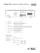 RDC Reporter D20 Operating Information & Installation Instructions
-
Raycus RFL-C300L User manual
-
-
-
Analog Devices 126791-HMC764LP6C Operating instructions
-
APG MPX-E/R/E Chem Installation guide


