Netgear FS700TS User manual
- Category
- Network switches
- Type
- User manual
This manual is also suitable for

202-10150-01
December 2005
NETGEAR, Inc.
4500 Great America Parkway
Santa Clara, CA 95054 USA
Phone 1-888-NETGEAR
Hardware Installation
Guide for the Prosafe
Stackable Smart Switch
FS700TS Series

ii
v1.0, December 2005
© 2005 by NETGEAR, Inc. All rights reserved. December 2005.
Trademarks
@2005 NETGEAR, Inc. NETGEAR, the Netgear logo, Prosafe, The Gear Guy and Everybody's connecting are
trademarks of Netgear, Inc. in the United States and/or other countries.
Microsoft, Windows, and Windows NT are registered trademarks of Microsoft Corporation.
Other brand and product names are registered trademarks or trademarks of their respective holders.
Information is subject to change without notice. All rights reserved.
Statement of Conditions
In the interest of improving internal design, operational function, and/or reliability, NETGEAR reserves the right to
make changes to the products described in this document without notice.
NETGEAR does not assume any liability that may occur due to the use or application of the product(s) or circuit
layout(s) described herein.
Certificate of the Manufacturer/Importer
It is hereby certified that the NETGEAR Smart Fast Ethernet Switch with Gigabit Ports has been suppressed in
accordance with the conditions set out in the BMPT-AmtsblVfg 243/1991 and Vfg 46/1992.The operation of some
equipment (for example, test transmitters) in accordance with the regulations may, however, be subject to certain
restrictions. Please refer to the notes in the operating instructions.
Federal Office for Telecommunications Approvals has been notified of the placing of this equipment on the market and
has been granted the right to test the series for compliance with the regulations.
Voluntary Control Council for Interference (VCCI) Statement
This equipment is in the first category (information equipment to be used in commercial and/or industrial areas) and
conforms to the standards set by the Voluntary Control Council for Interference by Data Processing Equipment and
Electronic Office Machines that are aimed at preventing radio interference in commercial and/or industrial areas.
Consequently, when this equipment is used in a residential area or in an adjacent area thereto, radio interference may be
caused to equipment such as radios and TV receivers.
Federal Communications Commission (FCC) Compliance Notice: Radio Frequency Notice
This device complies with part 15 of the FCC Rules. Operation is subject to the following two conditions:
• This device may not cause harmful interference.
• This device must accept any interference received, including interference that may cause undesired operation.
Note: This equipment has been tested and found to comply with the limits for a Class A digital device, pursuant to part
15 of the FCC Rules. These limits are designed to provide reasonable protection against harmful interference in a
residential installation. This equipment generates, uses, and can radiate radio frequency energy and, if not installed and
used in accordance with the instructions, may cause harmful interference to radio communications. However, there is no
guarantee that interference will not occur in a particular installation. If this equipment does cause harmful interference to
radio or television reception, which can be determined by turning the equipment off and on, the user is encouraged to try
to correct the interference by one or more of the following measures:
• Reorient or relocate the receiving antenna.

Hardware Installation Guide for the Prosafe Stackable Smart Switch FS700TS Series
iii
v1.0, December 2005
• Increase the separation between the equipment and receiver.
• Connect the equipment into an outlet on a circuit different from that which the receiver is connected.
• Consult the dealer or an experienced radio/TV technician for help.
EU Declaration of Conformity
This is to declare that the NETGEAR Smart Fast Ethernet Switch with Gigabit Ports is compliant with EMC Directive
89/336/EEC and Low Voltage Directive 73/23/EEC. Conformity is declared by application of EN55022, Class A,
EN55024 and EN60950.
Canadian Department of Communications Radio Interference Regulations
This digital apparatus (NETGEAR Smart Fast Ethernet Switch with Gigabit Ports) do not exceed the Class A limits for
radio-noise emissions from digital apparatus as set out in the Radio Interference Regulations of the Canadian
Department of Communications.
Règlement sur le brouillage radioélectrique du ministère des Communications
Cet appareil numérique (NETGEAR Smart Fast Ethernet Switch with Gigabit Ports) respecte les limites de bruits
radioélectriques visant les appareils numériques de classe A prescrites dans le Règlement sur le brouillage
radioélectrique du ministère des Communications du Canada.
Customer Support
Refer to the Support Information Card that shipped with your NETGEAR Prosafe Stackable Smart Switch.
World Wide Web
NETGEAR maintains a World Wide Web home page that you can access at the universal resource locator (URL)
http://www.netgear.com. A direct connection to the Internet and a Web browser such as Internet Explorer
or Netscape are required.
Warning: This is a Class A product. In a domestic environment, this product may cause
radio interference, in which case the user may be required to take appropriate
measures.

Hardware Installation Guide for the Prosafe Stackable Smart Switch FS700TS Series
iv
v1.0, December 2005
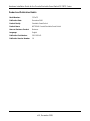
Product and Publication Details
Model Number: FS7xxTS
Publication Date: December 2005
Product Family: Stackable Smart Switch
Product Name: NETGEAR Prosafe Stackable Smart Switch
Home or Business Product: Business
Language: English
Publication Part Number: 202-10150-01
Publication Version Number: 1.0

Hardware Installation Guide for the Prosafe Stackable Smart Switch FS700TS Series
-1
v1.0, December 2005
Contents
Hardware Installation Guide for the Stacking Smart Switch FS700TS Series
Chapter 1
About This Manual
Audience, Scope, Conventions, and Formats ................................................................1-1
How to Use This Manual ................................................................................................1-2
How to Print this Manual .................................................................................................1-2
Chapter 2
Introduction
Overview .........................................................................................................................2-1
Stacking Features ...........................................................................................................2-3
Other Features ...............................................................................................................2-4
Application Example—Desktop Switching ......................................................................2-5
Package Contents ..........................................................................................................2-6
Panel Layout Guide ........................................................................................................2-7
FS728TS Front Panel ..............................................................................................2-7
FS752TS Front Panel ..............................................................................................2-8
FS752TPS Front Panel ............................................................................................2-9
LED Designations ..................................................................................................2-10
Front Panel Buttons ...............................................................................................2-12
Device Hardware Interfaces ...................................................................................2-13
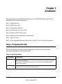
Chapter 3
Installation
Step 1: Preparing the Site ...............................................................................................3-1
Step 2: Installing the Switch ............................................................................................3-2
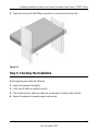
Installing the Switch on a Flat Surface .....................................................................3-2
Installing the Switch in a Rack .................................................................................3-2
Step 3: Checking the Installation ....................................................................................3-3
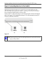
Step 4: Connecting Devices to the Switch ......................................................................3-4

Hardware Installation Guide for the Prosafe Stackable Smart Switch FS700TS Series
-2
v1.0, December 2005
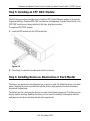
Step 5: Installing an SFP GBIC Module ..........................................................................3-5
Step 6: Installing Device as Stand-alone or Stack Master ..............................................3-5
Step 7: Applying AC Power ............................................................................................3-7
Step 8: Switch Management through a Web Browser or the PC Utility for Initial Configuration
3-7
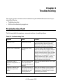
Chapter 4
Troubleshooting
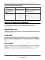
Troubleshooting Chart ....................................................................................................4-1
Additional Troubleshooting Suggestions ........................................................................4-2
Network Adapter Cards ............................................................................................4-2
Configuration ............................................................................................................4-2
Switch Integrity .........................................................................................................4-2
Auto-negotiation .......................................................................................................4-3
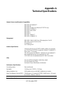
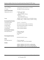
Appendix A
Technical Specifications
Appendix B
Related Documents

About This Manual 1-1
v1.0, December 2005
Chapter 1
About This Manual
This chapter describes the intended audience, scope, conventions, and formats of this manual.
Audience, Scope, Conventions, and Formats
This reference manual assumes that the reader has basic to intermediate computer and Internet
skills. However, basic computer network, Internet, firewall, and VPN technologies tutorial
information is provided in the Appendices and on the Netgear website.
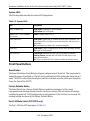
This guide uses the following typographical conventions:
This guide uses the following formats to highlight special messages:
Table 1-1. Typographical Conventions
italics Emphasis, books, CDs, URL names
bold User input
fixed Screen text, file and server names, extensions, commands, IP addresses
Note: This format is used to highlight information of importance or special interest.
Tip: This format is used to highlight a procedure that will save time or resources.
Warning: Ignoring this type of note may result in a malfunction or damage to the
equipment.

Hardware Installation Guide for the Prosafe Stackable Smart Switch FS700TS Series
1-2 About This Manual
v1.0, December 2005
This manual is written for the Prosafe Smart Switch according to these specifications:
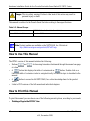
How to Use This Manual
The HTML version of this manual includes the following:
• Buttons, and , for browsing forwards or backwards through the manual one page
at a time
• A button that displays the table of contents and an button. Double-click on a
link in the table of contents or index to navigate directly to where the topic is described in the
manual.
• A button to access the full NETGEAR, Inc. online knowledge base for the product
model.
• Links to PDF versions of the full manual and individual chapters.
How to Print this Manual
To print this manual you can choose one of the following several options, according to your needs.
• Printing a Page in the HTML View.
Danger: This is a safety warning. Failure to take heed of this notice may result in
personal injury or death.
Table 1-2. Manual Scope
Product Version NETGEAR Prosafe Stackable Smart Switch
Manual Publication Date December 2005
Note: Product updates are available on the NETGEAR, Inc. Web site at
http://kbserver.netgear.com/products/FS7xxTS.asp.

Hardware Installation Guide for the Prosafe Stackable Smart Switch FS700TS Series
About This Manual 1-3
v1.0, December 2005
Each page in the HTML version of the manual is dedicated to a major topic. Use the Print
button on the browser toolbar to print the page contents.
• Printing a Chapter.
Use the PDF of This Chapter link at the top left of any page.
— Click the PDF of This Chapter link at the top right of any page in the chapter you want to
print. The PDF version of the chapter you were viewing opens in a browser window.
— Your computer must have the free Adobe Acrobat reader installed in order to view and
print PDF files. The Acrobat reader is available on the Adobe Web site at
http://www.adobe.com.
— Click the print icon in the upper left of the window.
• Printing the Full Manual.
Use the Complete PDF Manual link at the top left of any page.
— Click the Complete PDF Manual link at the top left of any page in the manual. The PDF
version of the complete manual opens in a browser window.
— Click the print icon in the upper left of the window.
Tip: If your printer supports printing two pages on a single sheet of paper, you can
save paper and printer ink by selecting this feature.
Tip: If your printer supports printing two pages on a single sheet of paper, you can
save paper and printer ink by selecting this feature.

Hardware Installation Guide for the Prosafe Stackable Smart Switch FS700TS Series
1-4 About This Manual
v1.0, December 2005

Introduction 2-1
v1.0, December 2005
Chapter 2
Introduction
Congratulations on the purchase of the NETGEAR Prosafe Stackable Smart Switch. The Prosafe
Smart Switch is a state-of-the-art, high-performance, IEEE-compliant network solution designed
for users who require a large number of ports and want the power of Gigabit connectivity to
eliminate bottlenecks, boost performance, and increase productivity. To simplify installation, the
switch is shipped ready for use out of the box.
This chapter serves as an introduction to the NETGEAR Prosafe Stackable Smart Switch and
provides the following information:
•Overview
• Switch Features
• Package contents
Overview
This Installation Guide is for the following NETGEAR Prosafe Stackable Smart Switch models:
• FS728TS—supports 24 ports of 10/100 BASE-T, 2 ports of 10/100/1000 BASE-T, and 2 GbE
combo (Copper/Fiber) ports
• FS752TS—supports 48 ports of 10/100 BASE-T, 2 ports of 10/100/1000 BASE-T, and 2 GbE
combo (Copper/Fiber) ports
• FS752TPS PoE—supports 48 ports of 10/100 BASE-T, 2 ports of 10/100/1000 BASE-T, and 2
GbE combo (Copper/Fiber) ports. This model supports the added feature of Power over
Ethernet (PoE).
These switches can be stacked together in a stack of up to six units, or a maximum of 192 10/100
ports, or can be used as stand-alone devices.

Hardware Installation Guide for the Prosafe Stackable Smart Switch FS700TS Series
2-2 Introduction
v1.0, December 2005
Using Gigabit ports, high-speed connections can be made to a server or network backbone.
Application examples include:
• Connecting switches to each other with high-speed links
• Linking to high-speed servers
• Providing 10/100/1000 copper and fiber connectivity
• The 2 10/100/1000 Base T ports are primarily used for stacking, but can alternatively be used
to provide additional bandwidth.
The NETGEAR Smart Switch also provides the benefit of administrative management with a
complete package of features for the observation, configuration, and control of the network. With a
Web-based Graphical User Interface (GUI), the switch's many capabilities can be viewed and used
in a simple and intuitive manner. The switch's management features include configuration for port
and switch information, VLAN for traffic control, port trunking for increased bandwidth, and
Class of Service (CoS) for traffic prioritization. These features provide better understand and
control of the network. Initial discovery of the switch on the network requires the Smart Wizard
Discovery program, a utility that runs on a PC.
The NETGEAR Smart Switch can be free-standing, or rack mounted in a wiring closet or
equipment room. It is IEEE-compliant and offers low latency for high-speed networking. All ports
can automatically negotiate to the highest speed. This capability makes the switch ideal for
environments that have a mix of Ethernet, Fast Ethernet, or Gigabit Ethernet devices. In addition,
all RJ-45 ports operate in half- or full-duplex mode, increasing the maximum bandwidth of each
connection up to either 20 Mbps, 200 Mbps, or 2000 Mbps respectively. The maximum segment
length is 328 feet (100 meters) over Category 5 Unshielded Twisted-Pair (UTP) cable, but much
longer for fiber connections using SFP GBIC modules.

Hardware Installation Guide for the Prosafe Stackable Smart Switch FS700TS Series
Introduction 2-3
v1.0, December 2005
Stacking Features
Stacking provides multiple switch management through a single point as if all stack masters are a
single unit. All stack masters are accessed through a single IP address through which the stack is
managed. The stack is can be managed from the following:
• Web-based Interface
• SNMP Management Station
Devices support stacking up to six units per stack, or can operate as stand-alone units. Up to 192
10/100 ports are supported in a stack.
During the Stacking setup, the switches will auto-select one as the Stacking Master. All other
devices are named as slave stack members, and assigned a unique Unit ID. One of the slave units is
designated as the backup master. The backup master acts as a slave stack master, but can become a
stack master in the event of failure of stack master. The master and backup master are assigned
unit IDs of 1 and 2. The Stack Master provides a Single point of control and management as well
as a single interface in which to control and manage the stack.
Switch software is downloaded separately for each stack members. However, all units in the stack
must be running the same software version.
A stack unit can operate in one of the following Modes:
• Stand-alone—the unit runs as a general switch and does not run the stacking application.
• Master Unit—manages the Stack and is responsible for the configuration.
• Master-Backup—runs as a slave unit and monitors the operation of the stack master. If the
master unit fails, you must select the Master-Backup manually to assume the Stack-master
role. If a Master-Backup becomes the Master Unit, another Master-Backup will need to be
selected manually. One of the Slave units will not automatically become a Master-Backup.
• Slave—runs a slave version of the Switching Algorithm, which allows the applications
running on the master unit to control the resources of the slave unit.

Hardware Installation Guide for the Prosafe Stackable Smart Switch FS700TS Series
2-4 Introduction
v1.0, December 2005
Other Features
The following list identifies the key features of the NETGEAR Smart Switch.
• 24/48 RJ-45 10/100M auto sensing Fast Ethernet switching ports.
• 2-Port 10/100/1000M auto sensing Gigabit Ethernet switching ports. These ports are reserved
for stacking units together, but can be configured as user ports.
• 2 Small Form-factor Pluggable (SFP) GBIC slots which function as combo ports. Combo ports
are single ports with two physical connections, SFP fiber and RJ-45 copper. The RJ-45 copper
ports corresponding to the Combo ports are the last 2 10/100/1000M auto sensing Fast
Ethernet switching ports on each device. If both devices are plugged in, the fiber connection is
active, with fiber port taking priority if both are connected.
• FS700TS devices support full Netgear Smart Switch function.
• FS700TS devices provide full compatibility with IEEE standards:
– IEEE 802.3i, (10BASE-T)
– IEEE 802.3u (100BASE-TX)
– IEEE 802.3x (Full-duplex flow control)
– IEEE 802.3ab (1000BASE-T)
– IEEE 802.3z (1000BASE-X)
• Auto-sensing and auto-negotiating capabilities for all ports.
• Automatic address learning function to build the packet-forwarding information table. The
table contains up to 8K media access control (MAC) addresses.
• Full- and Half-duplex functions for all 10/100Mbps ports.
• Store-and-Forward transmission to remove bad packets from the network.
• Full-duplex IEEE 802.3x pause frame flow control.
• Active flow control to minimize packet loss/frame drops.
• Half-duplex back-pressure control.
• Per port LEDs, Power supply LED, Master LED and Stack ID indication.
• Internal power supply.
• Standard 1U high, rack mountable 17" chassis.

Hardware Installation Guide for the Prosafe Stackable Smart Switch FS700TS Series
Introduction 2-5
v1.0, December 2005
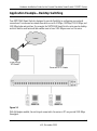
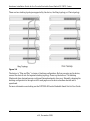
Application Example—Desktop Switching
Your NETGEAR Smart Switch is designed to provide flexibility in configuring your network
connections. It can be used as a stand-alone device or with 10 Mbps, 100 Mbps, 10/100 Mbps, and
1000 Mbps hubs and switches. For example, the NETGEAR Smart Switch can be used as desktop
switch to build a small network that enables users to have 1000 Mbps access to a file server.
With full-duplex enabled, the switch port connected to the server or PC can provide 2000 Mbps
throughput.
Figure 2-1

Hardware Installation Guide for the Prosafe Stackable Smart Switch FS700TS Series
2-6 Introduction
v1.0, December 2005
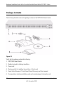
Package Contents
The following illustration shows the package contents of the NETGEAR Smart Switch.
Verify that the package contains the following:
1. NETGEAR Smart Switch
2. Rubber footpads for tabletop installation
3. Power cord
4. Rack-mount kit for installing the switch in a 19-inch rack
5. Smart Switch Resource CD with Smart Wizard Discovery and User's manual
6. Documentation including installation guide and warranty/support information card
Figure 2-2

Hardware Installation Guide for the Prosafe Stackable Smart Switch FS700TS Series
Introduction 2-7
v1.0, December 2005
If any item is missing or damaged, contact the place of purchase immediately.
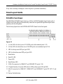
Panel Layout Guide
FS728TS Front Panel
The NETGEAR FS728TS Smart Switch is a 24-Port 10/100M Stackable Smart Switch with 4
Gigabit Ports. Each RJ45 port automatically senses the line speed and negotiates duplex mode
operation with the link partner.
The following figure shows the NETGEAR FS728TS Smart Switch front panel:
1. (1a-1m) LEDs for the top row of 10/100M ports (odd-numbered ports 1-23)
2. (2a-2m) LEDs for the bottom row of 10/100M ports (even-numbered ports 2-24)
3. LED for the top-most SFP port (port 25F)
4. LED for the bottom-most SFP port (port 26F)
5. Reset button
6. Stack ID LED
7. Power LED
8. Stack Master LED
9. 24 RJ-45 connectors for 10BASE-T and 100BASE-TX (ports 1-24)
10. 2 Gigabit Interface Converter SFP slots for SFP modules (ports 25F and 26F)
11. 4 RJ-45 connectors for 10BASE-T, 100BASE-TX and 1000BASE-T (ports 25T, 26T, 27, and
28)
12. Factory Defaults button
Figure 2-3

Hardware Installation Guide for the Prosafe Stackable Smart Switch FS700TS Series
2-8 Introduction
v1.0, December 2005
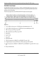
FS752TS Front Panel
The NETGEAR FS752TS Smart Switch is a 48-Port 10/100M Stackable Smart Switch with 4
Gigabit Ports. Each RJ45 port automatically senses the line speed and negotiates duplex mode
operation with the link partner.
The following figure shows the NETGEAR FS752TS Smart Switch front panel:
1. (1a-1y) LEDs for the top row of 10/100M ports (odd-numbered ports 1-47)
2. (2a-2y) LEDs for the bottom row of 10/100M ports (even-numbered ports 2-48)
3. LED for the top-most SFP port (port 49F)
4. LED for the bottom-most SFP port (port 50F)
5. Reset button
6. Stack ID LED
7. Power LED
8. Stack Master LED
9. 24 RJ-45 connectors for 10BASE-T and 100BASE-TX (ports 1-48)
10. 2 Gigabit Interface Converter SFP slots for SFP modules (ports 49F and 50F)
11. 4 RJ-45 connectors for 10BASE-T, 100BASE-TX and 1000BASE-T (ports 49T, 50T, 51, and
52)
12. Factory Defaults button
Figure 2-4

Hardware Installation Guide for the Prosafe Stackable Smart Switch FS700TS Series
Introduction 2-9
v1.0, December 2005
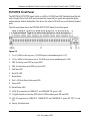
FS752TPS Front Panel
The NETGEAR FS752TPS Smart Switch is a 48-Port 10/100M and PoE Stackable Smart Switch
with 4 Gigabit Ports. Each RJ45 port automatically senses the line speed and negotiates duplex
mode operation with the link partner. The device also offers 24 PoE (Power over Ethernet) enabled
ports.
The following figure shows the NETGEAR FS752TPS Smart Switch front panel:
1. (1a-1y) LEDs for the top row of 10/100M ports (odd-numbered ports 1-47)
2. (2a-2y) LEDs for the bottom row of 10/100M ports (even-numbered ports 2-48)
3. LED for the top-most SFP port (port 49F)
4. LED for the bottom-most SFP port (port 50F)
5. PoE Max LED
6. Stack ID LED
7. Reset button
8. Port 1-24 Mode Select button and LED
9. Power LED
10. Stack Master LED
11. 24 RJ-45 connectors for 10BASE-T and 100BASE-TX (ports 1-48)
12. 2 Gigabit Interface Converter SFP slots for SFP modules (ports 49F and 50F)
13. 4 RJ-45 connectors for 10BASE-T, 100BASE-TX and 1000BASE-T (ports 49T, 50T, 51, and
52)
14. Factory Defaults button
Figure 2-5

Hardware Installation Guide for the Prosafe Stackable Smart Switch FS700TS Series
2-10 Introduction
v1.0, December 2005
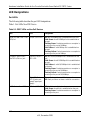
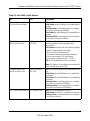
LED Designations
Port LEDs
The following table describes the port LED designations.
Table 1. Port LEDs Non-POE Device
Table 2-1. PORT LEDs on Non-PoE Devices
Port LED Designation
24/48 10/100M Ports—One
LED/Port
Link/ACT/SPD LED Off : No 10/100Mbps link is established on the port.
Solid Green: A valid 100Mbps link is established on
the port.
Flashing Green: Packet transmission or reception is
occurring on the port at 100Mbps.
Solid Yellow: A valid 10Mbps link is established on
the port.
Flashing Yellow: Packet transmission or reception is
occurring on the port at 10Mbps.
4 Gigabit Copper Ports—
Two LED's/Port on Jack
Left LED Link/ACT/
SPD LED:
Off : No 10/100/1000Mbps link is established on the
port.
Solid Green: A valid 1000Mbps link is established on
the port.
Solid Yellow: A valid 10/100Mbps link is established
on the port.
Flashing Green: Packet transmission or reception is
occurring on the port at 1000Mbps.
Flashing Yellow: Packet transmission or reception is
occurring on the port at 10/100Mbps.
Right LED Stack
LED (Combo port
group/Copper port
group):
Green: Stack port has a valid link connection.
Off: Stack port does not have a valid link connection.
2 SFP Ports—One LED/Port SFP Link/ACT LED Off: No link is established on the port.
Solid Green: A valid link is established on the port.
Flashing Green: Packet transmission or reception is
occurring on the port.
Page is loading ...
Page is loading ...
Page is loading ...
Page is loading ...
Page is loading ...
Page is loading ...
Page is loading ...
Page is loading ...
Page is loading ...
Page is loading ...
Page is loading ...
Page is loading ...
Page is loading ...
Page is loading ...
Page is loading ...
Page is loading ...
Page is loading ...
Page is loading ...
Page is loading ...
Page is loading ...
Page is loading ...
Page is loading ...
-
 1
1
-
 2
2
-
 3
3
-
 4
4
-
 5
5
-
 6
6
-
 7
7
-
 8
8
-
 9
9
-
 10
10
-
 11
11
-
 12
12
-
 13
13
-
 14
14
-
 15
15
-
 16
16
-
 17
17
-
 18
18
-
 19
19
-
 20
20
-
 21
21
-
 22
22
-
 23
23
-
 24
24
-
 25
25
-
 26
26
-
 27
27
-
 28
28
-
 29
29
-
 30
30
-
 31
31
-
 32
32
-
 33
33
-
 34
34
-
 35
35
-
 36
36
-
 37
37
-
 38
38
-
 39
39
-
 40
40
-
 41
41
-
 42
42


Netgear FS700TS User manual
- Category
- Network switches
- Type
- User manual
- This manual is also suitable for
Ask a question and I''ll find the answer in the document
Finding information in a document is now easier with AI
Related papers
-
Netgear GS748TR-100NAS User manual
-
Netgear 748TS User manual
-
-
-
-
-
-
-
Netgear FS752TS - ProSafe Smart Switch User manual
-
Other documents
-
Trendnet TE100-SFXM Owner's manual
-
MicroNet SP6524PWS Quick Installation Guide
-
Trendnet TPE-224WS User guide
-
D-Link DES-1526 User manual
-
Allnet ALL0484W User guide
-
-
Comelit IPSWP22N01A User manual
-
Perle IDS-509CPP Quick start guide
-
-
Black Box PIN POINT TS020A User manual