Page is loading ...

INSTRUCTION MANUAL
X-Wedge for LX200 and LX600 telescopes
55-12003_07028_XWedge_InstructionManual.indd 1 8/8/2012 11:07:49 AM

AutoStar #497 HANDBOX
X-Wedge Instruction Manual
1
This Meade X-Wedge is designed for use with the Meade Giant
Field Tripod.
Warning: If the telescope is placed on the wedge without
the field tripod attached to it, the wedge will be seriously
overbalanced and the telescope could tip over.
The X-Wedge instructions are written for use with either the
Meade Standard Field or Giant Field Tripod. The assembly
procedure requires two people who can lift about 55 pounds
each.
X-Wedge Assembly
The required wedge hardware is shipped within the wedge
carton (Fig. A).
1. Locate the two 8-32 hex screws and the tangent
arm (Fig. A, 6).
2. Attach the tangent arm to the tripod using the
supplied 8-32 hex screws. Note: the flat surface
of the tangent arm should face upwards (Fig. D).
X-WEDGE OPERATING MANUAL
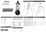
Figure C. Parts of the X-Wedge. (1) Tilt-plate; (2) Mounting slot
at top of tilt plate; (3) Latitude lock screw (one on each side);
(4) Vernier pointer; (5) Latitude Scale; (6) Azimuth Control Knob;
(7) Wedge Body; (8) Plate center hole; (9) Latitude control screw
(adjustment knob not shown); (10) Mounting slots; (11) Center
bolt hole.
2
3
4
6
5
1
7
8
9
1!
Figure B. Fully assembled tripod.
1 Tripod Head
2 Threaded Rod
3 T-handle
Tension Knob
4 Spreader
5 Leg Lock Knobs
6 Extension Strut
7 Tension Hub
8 Retaining clip
(not visible)
1
2
3
4
5
6
7
8
Figure A. Hardware kit for the X-Wedge.
1 Hex wrenches (3)
4 3/8" hex screws (3)
and washers (3)
2 Center mounting
bolt (1) and washer (1)
6 Tangent
arm (1) and
connecting
8-32 hex
screws (2)
5 5/16" hex
screws (3)
and
washers (3)
3 Threaded rod cap (1)
and threaded rod sleeve insert (1)
Figure D. Attach the tangent arm with the flat surface facing up.
55-12003_07028_XWedge_InstructionManual.indd 1 8/8/2012 11:07:51 AM

2
X-Wedge Instruction Manual
3. Place the wedge on the tripod head, sliding the
azimuth thrust bar pin into the tangent arm slot
(Fig. E).
4. Push the tripod threaded rod (Fig. B, 2) up so
that the rod extends through the X-Wedge plate
center hole (Fig C, 8).
5. Screw the threaded rod insert onto the threaded
rod until it is seated firmly on the X-Wedge base
plate, fitted in plate center hole (Fig. F).
6. Align the tripod spreader bar with the tripod legs
as shown in Fig, B. Tighten the tripod t-handle
tension knob to a snug fit. Screw the threaded
rod cap onto the end of the threaded rod.
7. Using the three 5/16" hex screws and washers
(Fig. A, 5) pass the hex screws through the oval
slots on the wedge floor and thread them into the
tripod head (Fig. G).
8. The latitude lock screw (Fig. H) is installed at the
factory to allow the tilt plate to be adjusted for
any latitude greater than 25° and less than 57°.
If viewing in a region with a latitude from 57° to
65°, unthread the lock screw with the supplied
hex key wrench and move the screw to the
optional mounting hole.
Mounting the Telescope
on the X-Wedge
1. Thread one of the provided 3/8" hex screws into
the hole on the underside of the telescope drive
base. The desired hole is located at the curved
Figure E. The azimuth thrust bar pin positioned in the
tangent arm.
Azimuth thrust bar pin
Figure F. The Threaded rod insert properly positioned on the
threaded rod and X-Wedge base plate.
Figure G. X-Wedge with threaded rod cap and 5/16" hex screws
secured.
Figure I. Attach one of the 3/8" hex screws to the curved part of
the telescope drive base.
Figure H. Latitude screw with multiple lock screw positions.
Latitude lock screw
(in 25˚ to 57˚ position
Latitude lock screw
hole for 32˚ to 65˚
55-12003_07028_XWedge_InstructionManual.indd 2 8/8/2012 11:07:51 AM

AutoStar #497 HANDBOX
X-Wedge Instruction Manual
3
end of the telescope drive base (see Fig. I). Be
sure to leave approx, 3/4" of the screw exposed
to allow for clearance of the wedge tilt plate.
2. Grasp the two fork arms of the telescope firmly,
with the control panel toward the floor, place the
telescope onto the wedge tilt plate (Fig. A, 1) by
sliding the mounting screw on the telescope base
into the slot at the top tilt plate (Fig. J).
3. Insert the center mounting bolt (Fig. K) through
the center of the underside of the tilt plate and
into the underside of the drive base. Firmly
tighten the bolt. Do not overtighten.
Note: It is important to insert the center mounting bolt into the
wedge-telescope assembly. The center mounting bolt insures the
precise pointing accuracy of the X-Wedge.
4. Insert the two remaining 3/8" hex screws
through the underside of the tilt plate (Fig. L)
and into the underside of the drive base. Firmly
tighten all three 3/8" hex screws at this time. Do
Figure J. The telescope drive base placed on the
X-Wedge tilt plate.
not overtighten.
The telescope is now fully mounted onto the wedge and field
tripod. Adjustments in wedge latitude angle and/or azimuth
orientation may be made with the telescope in place.
Setting the Observing Latitude
Look up the latitude of the desired observing site (most road
maps show latitude lines). Then, loosen the latitude lock screws
(Fig. C, 3) and rotate the fine latitude control knob (Fig. C, 9)
while reading the latitude scale (Fig. C, 5). The latitude pointer
is a vernier scale (Fig. C, 4) which will allow the tilt angle to be
set to within 0.25°. When the tilt plate is aligned with the desired
latitude, tighten the latitude locking screws.
Aligning on Polaris
Begin aligning the telescope by locating Polaris. Finding Polaris
is simple. Most people recognize the “Big Dipper. The Big Dipper
has two stars that point the way. Polaris is the last star in the
“handle” of the Little Dipper (Fig. M).
Once you have located Polaris in the sky, orient your telescope
Figure K. Attaching the center mounting bolt.
Figure L. Use the provided hex wrench to secure the three 3/8"
hex screws into the telescope drive base.
Fig. M. Locating Polaris
55-12003_07028_XWedge_InstructionManual.indd 3 8/8/2012 11:07:52 AM

4
X-Wedge Instruction Manual
so that the control panel faces north (towards Polaris). You may
need to pick-up and rotate the telescope on its tripod to achieve
this orientation. The telescope and X-Wedge are now pointing
very near to the celestial north. Loosen the DEC lock, rotate the
OTA so that it is 90 degrees to the base (pointing towards Polaris)
and then relock the DEC. If you were to have performed this
maneuver perfectly, you would be able to see Polaris through the
finder scope (make sure that you aligned the finderscope to the
OTA). If you cannot, rotate the entire telescope/tripod assembly
until you can.
You are now ready to perform one of the AutoStar equatorial
alignment procedures. Consult your telescope’s instruction
manual for exact details.
Aligning the Magnetic Compass
With the aid of the magnetic compass, a telescope can be polar
aligned in locations where the view of Polaris is obstructed or
even before the skies get dark. The compass face has an angular
scale from 0 to 360 degrees which will be useful in adjusting for
the local angle of Magnetic Declination—the difference between
Magnetic North (which the compass shows) and true north
(where the telescope should be pointed).
Note: Magnetic Declination should not be confused with the
astronomical term “Declination” which, when used with “Right
Ascension,” describes the celestial coordinate system.
1. Setting Magnetic Declination:
a. In order to obtain an accurate reading using
the compass, you first need to determine the
Magnetic Declination of the observing area by
referring to the Magnetic Declination Map (Fig
O). Locate this value on the compass face for
future reference.
NOTE: East Magnetic Declination means True North is to the right
of the Magnetic North position and West Magnetic Declination
means True North is left of the Magnetic North position. For
example, Fig. O shows the correct setting for 13.5° East
Declination which covers Irvine, CA. The compass scale markings
range from 0 to 360 degrees azimuth so for East Magnetic
Declinations subtract the East Magnetic Declination value from
360 to obtain the correct reference mark on the compass face.
b. While holding the compass, rotate it so the
red compass arrow points in the direction of
Magnetic North. The arrow should be directly
over the "N" marking on the compass face.
c. Now place the compass onto the flat base
of the X-Wedge as shown in Fig N. Verify the
compass is still pointing toward Magnetic North
and the bubble level is properly centered. If the
bubble is not centered, adjust the tripod legs
until centered.
2. Finding True North:
The magnetic compass is now ready for use.
Follow these simple steps for a quick and easy
azimuth alignment.
a. Slightly loosen the three 5/16" hex screws
in the wedge floor to allow for rotation of the
X-Wedge.
b. Using the Azimuth Control Knob (Fig C,
6), manually adjust the X-wedge around the
Figure O. Compass bearing adjusted for Irvine, CA's
magnetic declination.
Figure N. Compass level placed on the X-Wedge.
55-12003_07028_XWedge_InstructionManual.indd 4 8/8/2012 11:07:52 AM

AutoStar #497 HANDBOX
X-Wedge Instruction Manual
5
threaded rod (without moving the compass)
until the red compass arrow points toward the
observing sites Magnetic Declination found in
step 1.
c. Tighten the t-handle tension knob, locking the
X-Wedge into place.
d. Retighten the 5/16" hex screws on the wedge
floor. Do not over tighten.
The tripod and X-Wedge are now pointed very near celestial
north and ready to run one of the alignment procedures.
55-12003_07028_XWedge_InstructionManual.indd 5 8/8/2012 11:07:52 AM

6
X-Wedge Instruction Manual
Figure P. Magnetic declination map of North America.
55-12003_07028_XWedge_InstructionManual.indd 6 8/8/2012 11:07:52 AM

AutoStar #497 HANDBOX
X-Wedge Manual
14-2118-00 071112
55-12003
Meade Instruments Corp.
27 Hubble
Irvine, CA 92618
800-626-3233
www.meade.com
Follow us on facebook and twitter for updates.
MEADE LIMITED WARRANTY
Every Meade telescope, spotting scope, and telescope accessory is warranted by Meade Instruments Corp. (“Meade”) to be free of
defects in materials and workmanship for a period of ONE YEAR from the date of original purchase in the U.S.A. and Canada. Meade will
repair or replace a product, or part thereof, found by Meade to be defective, provided the defective part is returned to Meade, freight-
prepaid, with proof of purchase. This warranty applies to the original purchaser only and is non-transferable. Meade products purchased
outside North America are not included in this warranty, but are covered under separate warranties issued by Meade international
distributors.
RGA Number Required: Prior to the return of any product or part, a Return Goods Authorization (RGA) number must be obtained from
Meade by writing, or calling (800) 626-3233. Each returned part or product must include a written statement detailing the nature of the
claimed defect, as well as the owner’s name, address, and phone number.
This warranty is not valid in cases where the product has been abused or mishandled, where unauthorized repairs have been attempted
or performed, or where depreciation of the product is due to normal wear-and-tear. Meade specifically disclaims special, indirect,
or consequential damages or lost profit which may result from a breach of this warranty. Any implied warranties which cannot be
disclaimed are hereby limited to a term of one year from the date of original retail purchase.
This warranty gives you specific rights. You may have other rights which vary from state to state.
Meade reserves the right to change product specifications or to discontinue products without notice.
55-12003_07028_XWedge_InstructionManual.indd 7 8/8/2012 11:07:53 AM
/