Page is loading ...

Note: Please read this instruction carefully for correct use of the product and preserve it for reference purposes.
All the examples and pictures used here are for reference only. There may be several technically incorrect places
or printing errors in this manual. The updates will be added into the new version of this manual. The contents of
this manual are subject to change without notice.This device should be operated only from the type of power
source indicatedon the marking label. The voltage of the power must be verified before using the same.
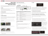
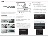
Network Video Recorder
Quick Start Guide
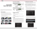
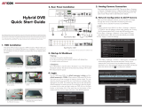
This series of the product supports 8 SATA hard drives.
The pictures of the installation are only for reference, please take the
real object as standard. Please make sure that the device is powered off
before installation
3. Install the mounting bar with HDDs back to the device.
4. Connect the power and data cables.
5. Install the upper four HDDs as the method mentioned above and
install back cover
Please check the device and the accessories after getting the device.
If there are any damages, shortages or defects, please contact your
dealer immediately.
For our HN500 series NVRs, the default username is admin and the
default password is 123456. When starting HN500 series NVR for
the first time, you will see a prompt to begin a startup wizard. You can
skip this wizard if you would like, but it will help you configure basic
settings for your NVR. The wizard may allow you to also change the
default password for better security. If you decide to skip the wizard,
to access the live view and start using your NVR click on the Start
button in the bottom left of the menu bar on the bottom of the
screen and then click on Login and enter in the default password.
2. HDD Installation
1. Packing Check
3. Rear Panel Installation
The interfaces of the rear panel are for reference only.
• Startup
1. Connect the monitor and the power.
2. The device will boot and the power indicator will display blue.
3. A wizard window will pop up.
• Shutdown
Go to “Main Menu” and then select “Shutdown” icon. This will bring
up a shutdown window. The device will shut down by clicking “OK”
button. Then disconnect the power.
4. Startup & Shutdown
4. Login
Username
Password
admin
Login
Enter Password
Display Password Log In Automatically
LoginEdit Security Question Cancel
After you finish adding IP cameras, you can see the live images through
the monitor of the NVR. The following will mainly introduce how to add
the IP cameras via LAN/WAN. This NVR has two network ports, you can
select the network work pattern as required. Network fault tolerance
and multiple address setting are optional.
Network Fault Tolerance: Bound two network ports to one IP address.
This pattern can increase the network bandwidth and form a network
redundant array to share the load. When one port goes wrong, the
otehr port will take over the entire load immediately and seamlessly.
Multiple Address Setting: You shall set the IP address, subnet mask,
gateway and DNS of each ethernet port respectively.
The pictures are only for referenc, please refer to User anua for details
5. Network Configuration
• LAN
1. Set the network of the NVR. Go to Start Settings
Network TCP/IP. Input IP address, subnet mask, gateway,
etc. If using DHCP, please enable DHCP in both the NVR and
the router.
2. Go to Start Settings Network Port. Input HTTP port
(the default value is 80), server port (the default port is 6036).
3. Click “Apply” to save the settings.
4. Go to Start Settings Camera Add Camera. The NVR
will automatically refresh the cameras searched. The IPC which
supports the Onvif protocol may be added manually. If the IPC
searched is not in the same local network as the NVR, you
should select the device and click to modify the IP address.
Remove the cover and loosen the screws to take out two mounting bars.
Get ready the HDDs installed and fix the HDDs on the mournting bar.
(For installing the HDDs well, please fix the round screw holes first)
Inter net
12
LA N 2
LA N 1
AU DIO
IN
AU DIO
OU T
HD MI 2
HD MI 1
US B
US B3. 0
VG A
e- SATA 1
e- SATA 2
8
1
3
5
7
2
4
6
GND
NO1
NO2
NO 3
NO4
GND
COM 1
COM 2
COM 3
COM 4
Z Y
B A
P/ Z
K/ B
AL ARM O UT
AL ARM I N
RS 4 85
IP Address Settings
Obta in an IPv 4 addre ss auto matic ally
Obta in DNS au tomat icall y
Obta in an IPv 6 addre ss auto matic ally
Ethernet Port 1 ( On line )
Ethernet Port 2 ( On line )
Addr ess
MCA Addr ess
Addr ess
MAC Add ress
192 . 16 8 . 1 . 2
10 . 151 . 1 51 . 1
0 . 0 . 0 . 0
. . .
0
192 . 16 8 . 1 . 1
Netw ork Fau lt Toleranc e
Ethe rnet Po rt 1
1500
Subn et Mask
Preferred DNS
Mask L ength
Gate way
Prim ary Car d
Work Pat tern (Mod ifyin g work pa ttern n eed to re boot )Gat eway
Gate way
MTU
3.4.2
3.4.2
4.0.0.1.beta1
Version
80
80
80
No.
Address
EditPort
Protocol Model
Subnet Mask
1
2
3
192.168.1.20
192.168.1.38
192.168.2.45
XXX
XXX
XXX
XXX
XXX
XXX
255.255.255.0
255.255.255.0
255 255 255 0. . .
Quickly Add
Manually Add
Add Recorder
Add Camera
Selected: 1/3
Add
Default Password
Remain Bandwidth: 108 / 120 Mb
Cancel
Mac Address
Address Sync to IPC
Edit Camera
192 .168 . 1 . 45
255 . 255 . 255 . 0
admin
192 .168 . 1 . 1
Subnet Mask
Username
Gateway
Password
OK Cancel
CE :98 :23 :75 :35 :22

6. UPnP
7. NAT
• WAN
1. Set the network of the NVR. Go to Start Settings Network
TCP/IPv4. Input static IP address or enable PPPoE and then
input the user name and password received from your ISP.
2. Go to Start Settings Camera. Click “Add Camera” or behind
the column of the search camera and select “Manually Add” to add
the IP cameras. Input IP address, server port, username and password
of the IP camera. The IP camera must be connected over WAN. And
here the IP address of the IP camera must be a WAN IP address.
• NAT Setting
You can use the UPnP function to enable the fast connection of
the device to WAN via a router without port mapping.
1. Go to Start Settings Network UPnP, and enable UPnP
and then click “Apply” button to save.
2. Enable the UPnP function in the router.
3. Click “Refresh” button to refresh the UPnP status. If the UPnP
status were still “Invalid UPnP” after refreshing it for several times,
the port would be wrong. Please change the mapping type to
“Manual” and then click to modify the port until the UPnP
status turns to “valid UPnP”.
1. The NVR shall be powered on and connected to the network.
2. Go to Start Settings Network TCP/IP. You can obtain
the IP address, subnet mask and gateway automatically.
You can also manually enter them according to the actual network
situation. Please make sure the network segment is the same as
that of the network which is used.
3. Set the preferred or alternative DNS Server. Click “Apply” to
save the parameters.
4. Go to Start Settings Network NAT tab. Enable NAT and
select the NAT Server Address (The default NAT Server Address
is nat.autonat.com). Click “Apply” to save the parameters.
Enter Password
Enter Username
Enter device serial number
Login
• NAT Access
After finishing the NAT settings, you can input www.autonat.com in
the IE address bar and then press enter to go to the following
interface. If you are the first time to access the NAT, you shall
download and install the ActiveX according to the popup tips.
After installing ActiveX successfully, it will pop the login box.
5. Checkmark the device you want to add and then click “Add” button.
The NVR will automatically refresh the cameras and return to
“Edit Camera” interface. “Online” status means connecting the device
successfully and you will see the live image. You may select the added
device and click button to modify channel, IP address, ect.
9. Manual Recording
Device Serial Number: Click on the menu bar at the bottom of
the live interface to check the serial number or go to Start Settings
Network Network Status to check the serial number of the DVR).
Username: The username of the NVR. The default username is admin.
Password: The password of the NVR. The password is set by yourself
when you configure the wizard for the first time.
Before recording, please install and format a HDD. In the live
interface you can see the menu toolbar. Click button to start
recording. Click it again to stop recording. You can also click to
check the status of the recording.
10. Playback
Click “Instant Playback” in the right-click menu of the camera’s
preview window to select or drag the playback progress bar
to change the playback time to play back the record.
Click on the tool bar at the bottom of the live preview
interface or click Start Playback to go to the playback interface
as shown below. You can also add the playback cameras manually.
Click in the playback window to pop up the “Add Camera”
window. Check the cameras in the window and then click “Add”
to add playback camera. The record files of the added playback
camera will be played in the playback interface.
• Instant Playback
• General Playback
Versi on
Edit
Upgr ade
Display Password
Camera Name
Address
Model
Edit Camera
XXX
192 .168 . 1 . 58
9008
admin
XXX
Port
Username
Protocol
Password
IP Camera 1
OKTest Cancel
No. Came ra Name
Addr ess
Port
Prot ocol
Mode l
Prev iew
Stat us
Edit Camera
Edit Camera Group IP Planning
Search Camera
1
2
3
192. 168.1.20
192. 168.1.38
192. 168.1.45
IP Camer a 1
IP Camer a 2
IP Camer a 3
XXX
XXX
XXX
4.1. 0.0
4.1. 0.0
4.1. 0.0
Onli ne
Offlin e
Onli ne
XXX
XXX
XXX
80
80
80
Sync to I PC
Rema in Band width : 85/12 0Mb
HTTP Port
HTTPS Port
Server Port
80
443
6036
80
443
183.17.254.19
183.17.254.19
Valid UPnP
Valid UPnP
Valid UPnP
Invalid UPnP
6036183.17.254.19
Port Type
External Port
External Address
UPnP Status Edit
Port
RTSP Port
554
554
AutoMap Type
UPnP
Enable
Refresh Apply
nat.autonat.com
NAT Server Address
Enable
Visit Address www.autonat.com
Apply
NAT
/