
1. Sauder Woodworking Co. (Sauder®) provides limited warranty coverage to the
original purchaser of this product for a period of fi ve years from the date of purchase
against defects in materials or workmanship of Sauder furniture components. As used in
this Warranty, “defect” means imperfections in components which substantially impair
the utility of the product. This Warranty gives you specifi c legal rights, and you may also
have other rights which vary from state to state.
2. There is no warranty coverage for defects or conditions that result from the failure
to follow product assembly instructions, information or warnings, misuse or abuse,
intentional damage, fi re, fl ood, alteration or modifi cation of the product, or use of the
product in a manner inconsistent with its intended use, nor any condition resulting
from incorrect or inadequate maintenance, cleaning, or care. There is also no warranty
coverage for rented products or any products purchased “used” or “as is”, at a distress or
going-out-of business sale, or from a liquidator.
3. As the exclusive remedy under this Warranty, Sauder will (at its sole option) repair
or replace any defective furniture component. Sauder may require independent
confi rmation of the claimed defect and proof of purchase. Replacement parts will be
warranted for only the remaining period of the original Warranty. SAUDER SHALL
HAVE NO LIABILITY for ANY INCIDENTAL OR CONSEQUENTIAL DAMAGES
OF ANY KIND and all such damages are EXCLUDED FROM THIS WARRANTY,
such as loss of use, disassembly, transportation, labor or damage to property on or
near the product. Some states do not allow the exclusion or limitation of incidental or
consequential damages, so the above limitation or exclusion may not apply to you.
4. This Warranty applies only to warranted defects that fi rst arise and are reported to
Sauder within the warranty coverage period. The Warranty cannot be transferred to
subsequent owners or users of the product, and it shall be immediately void in the event
the product is resold, transferred, leased or rented to any third party or person other than
the original purchaser.
5. THERE ARE NO OTHER WARRANTIES APPLICABLE TO THIS PRODUCT.
Under the laws of certain states, there may be no implied warranties from Sauder
and all implied warranties, INCLUDING ANY IMPLIED WARRANTY OF
MERCHANTABILITY OR FITNESS FOR A PARTICULAR PURPOSE are disclaimed
where allowed by law. TO THE EXTENT ANY IMPLIED WARRANTIES ARE
APPLICABLE, ANY IMPLIED WARRANTIES, INCLUDING ANY IMPLIED
WARRANTY OF MERCHANTABILITY OR FITNESS FOR A PARTICULAR
PURPOSE, ARE LIMITED IN DURATION TO THE DURATION OF THIS EXPRESS
WARRANTY or the minimum period allowed by law, whichever is shorter. Some states
do not allow limitations on how long an implied Warranty lasts, so the above limitation
may not apply to you.
6. For Warranty inquiries or claims, please visit our website www.sauder.com.
You can also contact Sauder at 1-800-523-3987. Sauder may require Warranty claims to
be submitted in writing to Sauder Woodworking Co., 502 Middle Street, Archbold, OH
43502 USA. Please include your sales receipt or other proof of purchase and a specifi c
description of the product defect.
5-YEAR LIMITED WARRANTY
GARANTIE LIMITÉE DE 5 ANS
1. Sauder Woodworking Co. (Sauder®) offre une couverture de garantie limitée à
l’acheteur initial du présent produit pendant une période de cinq ans à compter de la
date d’achat contre tout défaut de matériaux ou de fabrication des composantes de
mobilier Sauder. Le mot « défaut », tel qu’il est utilisé sous les termes de la présente
garantie, comprend les imperfections des pièces qui empêchent substantiellement
l’utilisation du produit. La présente garantie vous donne des droits légaux spécifi ques
et il est possible que vous ayez des droits supplémentaires variant d’État en État ou de
province en province.
2. La présente garantie ne saurait couvrir les défauts ou conditions qui surviendraient à la
suite du non respect des instructions, informations ou mises en garde de montage, d’une
mauvaise utilisation ou d’un abus, d’un dommage intentionnel, d’un incendie, d’une
inondation, d’une altération ou modifi cation du produit, d’une utilisation du produit
allant à l’encontre de son usage prévu, ni aucune condition résultant d’une maintenance,
d’un nettoyage ou d’un entretien inappropriés ou inadéquats. De plus, il n’existe aucune
garantie pour les produits loués ou tous les produits achetés « d’occasion » ou « en l’état
», dans le cadre d’une vente aux enchères ou de solde pour cessation de commerce, ou
auprès d’un liquidateur.
3. En tant que recours exclusif en vertu de la présente garantie, Sauder réparera ou
remplacera (sur sa seule décision) toute composante de mobilier défectueuse. Sauder peut
exiger une confi rmation indépendante du défaut revendiqué ainsi qu’une preuve d’achat. Les
pièces de rechange seront garanties uniquement pendant la période restante de la garantie
originale. SAUDER NE SERA EN AUCUN CAS RESPONSABLE de TOUT DOMMAGE
ACCESSOIRE OU CONSÉCUTIF DE TOUTE SORTE et lesdits dommages sont EXCLUS
DE LA PRÉSENTE GARANTIE, à savoir perte d’utilisation, démontage, transport, main
d’ceuvre ou dommages matériels sur ou à proximité du produit. Certains États ou provinces
ne permettant pas l’exclusion ou la limite aux responsabilités pour dommages accidentels ou
consécutifs, la limite ou l’exclusion ci-dessus peut ne pas être applicable.
4. La présente garantie ne s’applique qu’aux défauts garantis qui se produisent pour la
première fois et qui sont signalés à Sauder dans les limites de ouverture de la garantie.
La garantie ne peut pas être transférée à des propriétaires ou utilisateurs subséquents du
produit, et sera immédiatement invalidée dans le cas où le produit est revendu, transféré,
loué sous bail ou loué à une tierce partie ou personne autre que l’acheteur original.
5. IL N’EXISTE AUCUNE AUTRE GARANTIE EN VIGUEUR POUR LE PRÉSENT
PRODUIT. En vertu des lois de certains États ou provinces, il ne peut y avoir de garanties
implicites de la part de Sauder et toutes les garanties implicites, Y COMPRIS TOUTE
GARANTIE IMPLICITE DE COMMERCIABILITÉ OU D’ADAPTATION À UN
USAGE PARTICULIER sont déclinées partout où la loi l’autorise. DANS LA MESURE
OÙ TOUTE GARANTIE IMPLICITE EST APPLICABLE, TOUTE GARANTIE
IMPLICITE, Y COMPRIS TOUTE GARANTIE DE COMMERCIABILITÉ OU
D’ADAPTATION À UN USAGE PARTICULIER, EST LIMITÉE À LA DURÉE DE
LA PRÉSENTE GARANTIE EXPRESSE ou à la période minimum autorisée par la loi,
la période la plus courte étant retenue. Certains États ne permettant pas que des limites
soient imposées quant à la durée d’une garantie implicite, la limite ci-dessus peut donc ne
pas être applicable.
6. Pour toute question concernant la garantie ou toute demande de réclamation,
consulter le site Web www.sauder.com. Il est également possible de contacter
Sauder en composant le 1-800-523-3987. Sauder peut exiger de soumettre les demandes
de réclamation sous garantie par écrit à Sauder Woodworking Co., 502 Middle Street,
Archbold, OH 43502 USA. Veuillez joindre votre ticket de caisse ou toute autre preuve
d’achat ainsi qu’une description spécifi que du défaut de produit.
1.
Sauder Woodworking Co. (Sauder®) provee cobertura de garantía limitada al
comprador original de este producto por un período de cinco años, a partir de la fecha
de compra, contra defectos en los materiales o de mano de obra en los componentes de
muebles Sauder. Como es utilizado en esta Garantía, “defecto” signifi ca imperfecciones
en los componentes que de manera fundamental afecta la utilidad del producto. Esta
Garantía le permite a usted ciertos derechos legales, y usted también podría poseer otros
derechos adicionales, los cuales varían de estado a estado.
2. No hay cobertura de garantía para defectos o estados que resulten del incumplimiento
en seguir las instrucciones, la información o las advertencias sobre el ensamblaje del
producto; del uso incorrecto o maltrato, del daño intencional, incendio, inundación,
cambio o modifi cación del producto; o de la utilización del producto de manera
contradictoria con el uso para el cual fue fabricado, ni por ningún estado que resulte del
mantenimiento, limpieza o cuidado incorrecto o inadecuado. Tampoco no hay cobertura
de garantía para los productos rentados o para cualesquiera productos comprados “de
uso” o “como está”, en una venta de bienes embargados o en una venta por salirse del
negocio, o comprados a un liquidador.
3. Como un recurso exclusivo bajo esta Garantía, Sauder (sólo a su opción) reparará o
reemplazará cualquier componente defectuoso de mueble. Sauder puede requerir una
confi rmación independiente de un defecto reclamado y una prueba de compra. Las
piezas de repuesto serán garantizadas solamente por el período de tiempo que queda
de la Garantía original. SAUDER NO TENDRÁ RESPONSABILIDAD por NINGÚN
DAÑO INCIDENTAL O CONSECUENTE DE NINGÚN TIPO y todos dichos daños
SE EXCLUYEN DE ESTA GARANTÍA, tales como pérdida de uso, desensamblaje,
transportación, trabajo o daño a la propiedad en o cerca del producto. Algunos estados
no permiten la exclusión o limitación de daños incidentales o consecuentes, en tales
instancias la limitación o exclusión antes mencionada podría no ser aplicable a usted.
4. Esta Garantía sólo es aplicable a defectos garantizados que primeramente surjan
y se informen a Sauder dentro del período de cobertura de garantía. La Garantía no
puede ser transferida a propietarios o usuarios subsiguientes del producto, y ésta será
inmediatamente invalidada en el caso que el producto sea revendido, transferido,
arrendado o rentado a cualquier tercero u otra persona que no sea el comprador original.
5. NO HAY OTRA GARANTÍA APLICABLE A ESTE PRODUCTO. Bajo las
leyes de ciertos estados, pueden no haber garantías implícitas de Sauder y se hace
renuncia de responsabilidad de todas las garantías implícitas donde lo permita la ley,
INCLUYENDO CUALQUIER GARANTÍA IMPLÍCITA DE MERCANTIBILIDAD
O DE APTITUD PARA UN PROPÓSITO EN PARTICULAR. EN LA MEDIDA
CUALQUIER GARANTÍA IMPLÍCITA ES APLICABLE, CUALESQUIERA
GARANTÍAS IMPLÍCITAS, INCLUYENDO AQUELLA DE MERCANTIBILIDAD
O DE APTITUD PARA UN PROPÓSITO EN PARTICULAR, SE LIMITAN EN
DURACIÓN HASTA LA DURACIÓN DE ESTA GARANTÍA IMPLÍCITA o hasta el
periodo mínimo permitido por la ley, la que sea más corta. Algunos estados no permiten
limitaciones en cuanto a la duración de una garantía implícita, por eso la limitación
arriba citada pueda no ser aplicable a usted.
6. Para solicitud de información o reclamación de Garantía, por favor, visite nuestro
sitio Web www.sauder.com. Usted también puede contactar a Sauder llamando al
1-800-523-3987. Sauder puede solicitar que las reclamaciones sean presentadas por
escrito a Sauder Woodworking Co., 502 Middle Street, Archbold, OH 43502 EE.UU.
Por favor incluya su recibo de venta u otra prueba de compra y una descripción
detallada del defecto del producto.
GARANTÍA LIMITADA DE 5 AÑOS
411904


 1
1
 2
2
 3
3
 4
4
 5
5
 6
6
 7
7
 8
8
 9
9
 10
10
 11
11
 12
12
 13
13
 14
14
 15
15
 16
16
 17
17
 18
18
 19
19
 20
20


Sauder HomePlus Collection 411967 Operating instructions
 Signature Sleep 3215198 Owner's manual
Hay Shelving Unit User manual
Ryobi A99HPR1 Owner's manual
Craftsman CMHT77633 Owner's manual
 Closet Maid 3 Shelf Vertical Organizer 10130 User manual
Franklin Brass P43971K-FB-CP User manual
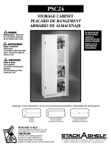 Closet Maid PSC24 User manual
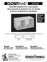 Closet Maid 10140 User manual
Stanley S300 Instructions Manual
YOTRIO Wicker Bar Assembly Instructions


