Page is loading ...

AcraDyne
5000 Series Nutrunners
Operations Manual
PO Box 16460, Portland OR 97292-0460 • 800-852-1368 • Fax 800-582-9015
www.aimco-global.com

Introduction
SAVE THESE INSTRUCTIONS
1) WORK AREA
a) Keep work area clean and well lit. Cluttered and dark areas invite accidents.
b) Do not operate power tools in explosive atmospheres, such as the presence of flammable liquids, gases or dust. Power tools create sparks which may ignite
the dust or fumes.
c) Keep children and bystanders away while operating a power tool. Distractions can cause you to lose control.
2) ELECTRICAL SAFETY
a) Power tool plugs must match the outlet. Never modify the plug in any way. Do not use any adapter plugs with earthed (grounded) power tools.
Unmodified plugs and matching outlets will reduce risk of electric shock.
b) Avoid body contact with earthed or grounded surfaces such a s pipes, radiators, ranges and refrigerators. There is an increased risk of electric shock if your
body is earthed or grounded.
c) Do not expose power tools to rain or wet conditions. Water entering a power tool will increase the risk of electric shock.
d) Do not abuse the cord. Never use the cord for carrying, pulling or unplugging the power tool. Keep cord away from heat, oil, sharp edges or moving parts.
Damaged or entangled cords increase the risk of electric shock.
e) This tool is intended for indoor use only.
3) PERSONAL SAFETY
a) Stay alert, watch what you are doing and use common sense when operating a power tool. Do not use a power tool while you are tired or under the
influence of drugs, alcohol or medication. A moment of inattention while operating power tools may result in serious personal injury.
b) Use safety equipment. Always wear eye protection. Safety equipment such as dust mask, non-skid safety shoes, hard hat, or hearing protection used for
appropriate conditions will reduce personal injuries. If the maximum duty cycle of the attached tool is exceeded or the tool temperature exceeds 50° C.,
then the operator should wear protective hand wear (gloves).
c) Avoid accidental starting. Ensure the switch is in the off-position before plugging in. Carrying power tools with your finger on the switch or plugging in
power tools that have the switch on invites accidents.
d) Remove any adjusting key or wrench before turning the power tool on. A wrench or a key left attached to a rotating part of the power tool may result in
personal injury.
e) Do not overreach. Keep proper footing and balance at all times. This enables better control of the power tool in unexpected situations.
f) Dress properly. Do no wear loose clothing or jewelry. Keep your hair, clothing and gloves away from moving parts. Loose clothes, jewelry or long hair
can be caught in moving parts.
g) If devices are provided for the connection of dust extraction and collection facilities, ensure these are connected and properly used. Use of these devices
can reduce dust-related hazards.
4) POWER TOOL USE AND CARE
a) Do not force the power tool. Use the correct power tool for your application. The correct power tool will do the job better and safer at the rate for which it
was designed.
b) Do not use the power tool if the switch does not turn it on and off. Any power tool that cannot be controlled with the switch is dangerous and must be
repaired.
c) This product is designed to be used in combination with the AcraDyne iEC DC tool controller for intermittent hand-held or fixtured assembly processes.
Safety Information
Thank you for purchasing this AcraDyne DC electric assembly tool, one of the lightest and fastest DC electric assembly tools
on the market. When used with the AcraDyne iEC tool controller, this tool will provide excellent productivity, ergonomics,
reliability and quality on a wide range of industrial assembly applications.
2

OPERATION
Angle Head
Tool Body
Multi Function
Button
Start Lever
Cable
Connection
Square/
Hex Drive
3
1. Connect tool cable to the iEC controller and the tool:
The tool cable has curved alignment tabs and slots
built into the connectors at each end to ensure proper
alignment and connection with the tool and controller.
Make sure that power is not turned on at the controller
before making any connections. Align the female connec-
tor on the cable with the male connector on the tool and insert
the cable onto the tool, then slide the connector nut onto the
threads on the cable and turn clockwise until hand-tight.
Align the male connector tab on the other end of the tool
cable with the female slot on the controller and insert the
cable into the connector, then slide the metal outer cover
onto the connection threads on the controller and turn clock-
wise until hand-tight.
2. Multifunction Button Operation:
The tool will flash all LED lights three times when power is
first turned on at the controller. After the controller finishes
initializing and displays a target toque value, the multifunction
button (MFB) is used to toggle the tool from clockwise mode
(FWD) to counter-clockwise operation mode (REV). The MFB
is the small button opposite the trigger.
The tool will initially start in clockwise mode and will have no
LED lights turned on. If the trigger is pressed, the tool will
turn on the blue LED meaning the tightening operation is
underway. Pressing the MFB will cause the tool to flash yel-
low and red LED lights. Pressing the MFB again will switch
the tool back FWD mode and will indicate this with no LED
lights turned on.
3. Start Lever Operation:
To start the tool, depress the start lever. Blue LED lights will
be displayed while tightening a bolt. The tool will stop auto-
matically when it senses its target torque value or if no torque
is sensed in a specified time period. After a cycle is complete,
the tool will display green LED lights for a success, or red
LED lights for failure to reach torque/angle.
A complete tool system consists of the following items:
Controller Power cord Tool Tool Cable
Light Ring Light Assignment
The Buzzer and Multi-Function Button are programmable in the
DSP Menu of ToolWare.
Light Color Meaning
Green Solid OK
Red Flashing Torque Low
Red Solid Torque High
Yellow Flashing Angle Low
Yellow Solid Angle High
Blue Solid Tool In-Cycle/Tool Armed
Blue Flashing P-Set Change thru MFB
All On Flashing Tool in Disassembly
Buzzer Bad Assembly/Tool in Disassembly/Power Up

PAGE HEADER HERE
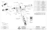
5000 SERIES ANGLE NUTRUNNERS
9
8
6
5
4
30
27
28
26
21 19
18
31
20
25
23
22
24
16
29
15
14
13
12
11
33
17
1
35
32
10
34
3
THIS SCREW IS ALREADY ASSEMBLED
INSIDE OF GEAR CARRIER ASSEMBLY
(SHOWN FOR CLARITY)
APPLY LOCTITE 243 (BLUE)
TIGHTEN TO 40 Nm (30 FT-LBS)
SEE NOTE #1
10
PRESS
ASSEMBLE THRU GROUND TERMINAL
APPLY LOCTITE 243 (BLUE)
TIGHTEN TO 1.4-1.6 Nm (12-14 IN-LBS)
APPLY LOCTITE 243 (BLUE)
TIGHTEN TO 1.4-1.6 Nm
(12-14 IN-LBS)
2 PLACES
APPLY LOCTITE 243 (BLUE)
TIGHTEN TO 8.3-8.5 Nm
(73-75 IN-LBS)
2 PLACES
PRESS FLUSH TO BELOW
MOTOR HOUSING DIAMETER
34
APPLY LOCTITE 243 (BLUE)
TIGHTEN TO 1.4-1.6 Nm
(12-14 IN-LBS)
5 PLACES
SEE NOTE #1
MOTOR PINION IS PART OF GEAR TRAIN
ASSEMBLY (SHOWN FOR CLARITY)
LUBRICATE INTERNAL O-RING PER NOTE #3
AND SLIDE PINION ONTO MOTOR SHAFT
UNTIL O-RING SEATS IN GROOVE.
APPLY LOCTITE 243 (BLUE)
TIGHTEN TO 1.9-2.5 Nm
(17-22 IN-LBS)
4 PLACES
APPLY LOCTITE 243 (BLUE)
TIGHTEN TO 1.9-2.5 Nm
(17-22 IN-LBS)
4 PLACES
APPLY LOCTITE 243 (BLUE)
TIGHTEN TO 1.4-1.6 Nm
(12-14 IN-LBS)
2 PLACES
30
APPLY LOCTITE 243 (BLUE)
TIGHTEN TO 1.4-1.6 Nm
(12-14 IN-LBS)
5 PLACES
LUBRICATE MOTOR SPLINE
SHAFT PER NOTE #1
APPLY LOCTITE 243 (BLUE)
TIGHTEN TO 2.5-2.9 Nm
(22-26 IN-LBS)
6 PLACES
33
2
APPLY LOCTITE 243 (BLUE)
TIGHTEN TO 1.4-1.6 Nm
(12-14 IN-LBS)
2 PLACES
SEE NOTE #3
TOOL LEVER
POSITION TOOL CONNECTOR
KEYWAY 90° FROM TOOL LEVER,
AS SHOWN
9
7
SEE NOTE #1
USED ONLY ON
TOOL MODEL AEN35090A
EXPLODED VIEW OF AEN35090A
TOOL ASSEMBLY
8
10
REF
REF
SUB-ASSEMBLY
3) O-RINGS: LUBRICATE WITH O-RING LUBE
2) BEARINGS: LUBRICATE WITH
CHEVRON SR1 GREASE
1) GEARS & SPLINES: LUBRICATE WITH DOW CORNING
MOLYKOTE BR2 PLUS GREASE.
ASSEMBLY INSTRUCTIONS
4
ITEM # PART NUMBER QTY. DESCRIPTION
1 26058 1 MOTOR ASM., 5000 SERIES
2 26198 1 THRUST WASHER
3 26074 1 BELLEVILLE WASHER
4 SEE CHART 1 GEAR TRAIN ASM.
5 20912 1 WAVE SPRING --- 3000 SERIES
6 SEE CHART 1 ASSEMBLY, GEAR CARRIER
7 SEE CHART 1 SPLINED SPINDLE SHAFT
8 20911 2 BELLEVILLE WASHER
9 SEE CHART 1 ASSY, RIGHT ANGLE HEAD
10 20913 4 PIN, RETAINING
11 26077 2 M-F THREADED HEX STANDOFF
12 26095 1 LED BOARD ASM.
13 26078 2 SCREW, SHC 4-40X.312, STEEL, BLACK OXIDE
14 26080 1 O-RING, LED LIGHT RING COVER
15 26079 1 LIGHT RING COVER, LED
16 26082 1 LEVER HANDLE
17 26088 6 SCREW, BHC 8-32X.25, STEEL, BLACK OXIDE
18 26102 1 TOOL CONNECTOR ASM., LEVER
19 25745 4 SCREW, BHC 4-40X.188, STEEL, BLACK OXIDE
20 25102 1 SCREW, BHC 4-40X.188, STEEL, BLACK OXIDE
21 25847 1 TID BOARD ASM.
22 24934 2 SCREW, FHC 4-40 X .312, STEEL, BLACK OXIDE
23 25071 1 SPRING, LEVER
24 25074 1 LEVER ASSEMBLY
25 20061 2 SCREW, LEVER
26 26084 1 HANDLE COVER, MFB
27 24706 1 REV BUTTON SUB-ASSEMBLY
28 24683 1 SPRING, REV BUTTON
29 24679 1 RETAINING RNG
30 24938 10 SCREW, FHSC 4-40X.188, STEEL, BLACK OXIDE
31 26083 1 HANDLE COVER
32 20534 1 3000 SERIAL/MODEL LABEL
33 26081 2 MOTOR HOUSING COVER
34 25385 8 SCREW, FHSC 6-32 X .375, STEEL
35 22141 1 SAFETY LABEL
MODEL NO. GEAR TRAIN ASM. GEAR CARRIER ASM. ANGLE HEAD ASM. SPLINED SPINDLE SHAFT
AEN35090A 26116 20924 26119 26122
AEN35140A 26116 20924 23461 N/A
AEN35175A 26115 26117 23461 N/A
AEN35225A 26114 20924 23468 N/A
AEN35285A 26112 20924 23468 N/A
AEN35350A 26111 26117 23468 N/A

PAGE HEADER HERE
5000 SERIES IN-LINE NUTRUNNERS
8
7
6
5
4
29
26
27
25
20
18
17
30
19
24
22
21
23
15
28
14
13
12
11
10
32
16
1
34
31
9
33
3
THIS SCREW IS ALREADY ASSEMBLED
INSIDE OF GEAR CARRIER ASSEMBLY
(SHOWN FOR CLARITY)
APPLY LOCTITE 243 (BLUE)
TIGHTEN TO 40 Nm (30 FT-LBS)
SEE NOTE #1
9
PRESS
APPLY LOCTITE 243 (BLUE)
TIGHTEN TO 1.4-1.6 Nm
(12-14 IN-LBS)
2 PLACES
APPLY LOCTITE 243 (BLUE)
TIGHTEN TO 8.3-8.5 Nm
(73-75 IN-LBS)
2 PLACES
PRESS FLUSH TO BELOW
MOTOR HOUSING DIAMETER
33
APPLY LOCTITE 243 (BLUE)
TIGHTEN TO 1.4-1.6 Nm
(12-14 IN-LBS)
5 PLACES
SEE NOTE #1
MOTOR PINION IS PART OF GEAR TRAIN
ASSEMBLY (SHOWN FOR CLARITY)
LUBRICATE INTERNAL O-RING PER NOTE #3
AND SLIDE PINION ONTO MOTOR SHAFT
UNTIL O-RING SEATS IN GROOVE.
APPLY LOCTITE 243 (BLUE)
TIGHTEN TO 1.9-2.5 Nm
(17-22 IN-LBS)
4 PLACES
APPLY LOCTITE 243 (BLUE)
TIGHTEN TO 1.9-2.5 Nm
(17-22 IN-LBS)
4 PLACES
APPLY LOCTITE 243 (BLUE)
TIGHTEN TO 1.4-1.6 Nm
(12-14 IN-LBS)
29
APPLY LOCTITE 243 (BLUE)
TIGHTEN TO 1.4-1.6 Nm
(12-14 IN-LBS)
5 PLACES
LUBRICATE MOTOR SPLINE
SHAFT PER NOTE #1
APPLY LOCTITE 243 (BLUE)
TIGHTEN TO 2.5-2.9 Nm
(22-26 IN-LBS)
6 PLACES
32
2
35
36
APPLY LOCTITE 243 (BLUE)
TIGHTEN TO 1.4-1.6 Nm
(12-14 IN-LBS)
ASSEMBLE THRU GROUND TERMINAL
APPLY LOCTITE 243 (BLUE)
TIGHTEN TO 1.4-1.6 Nm (12-14 IN-LBS)
APPLY LOCTITE 243 (BLUE)
TIGHTEN TO 1.4-1.6 Nm
(12-14 IN-LBS)
SEE NOTE #3
TOOL LEVER
POSITION TOOL CONNECTOR
KEYWAY 90° FROM TOOL LEVER,
AS SHOWN
SUB-ASSEMBLY
3) O-RINGS: LUBRICATE WITH O-RING LUBE
2) BEARINGS: LUBRICATE WITH
CHEVRON SR1 GREASE
1) GEARS & SPLINES: LUBRICATE WITH DOW CORNING
MOLYKOTE BR2 PLUS GREASE.
ASSEMBLY INSTRUCTIONS
5
ITEM # PART NUMBER QTY. DESCRIPTION
1 26058 1 MOTOR ASM., 5000 SERIES
2 26198 1 THRUST WASHER
3 26074 1 BELLEVILLE WASHER
4 SEE CHART 1 GEAR TRAIN ASM.
5 20912 1 WAVE SPRING --- 3000 SERIES
6 SEE CHART 1 ASSEMBLY, GEAR CARRIER
7 20911 2 BELLEVILLE WASHER
8 20923 1 INLINE HEAD ASSY - 1/2 IN DRIVE
9 20913 4 PIN, RETAINING
10 26077 2 M-F THREADED HEX STANDOFF
11 26095 1 LED BOARD ASM.
12 26078 2 SCREW, SHC 4-40X.312, STEEL, BLACK OXIDE
13 26080 1 O-RING, LED LIGHT RING COVER
14 26079 1 LIGHT RING COVER, LED
15 26082 1 LEVER HANDLE
16 26088 6 SCREW, BHC 8-32X.25, STEEL, BLACK OXIDE
17 26102 1 TOOL CONNECTOR ASM., LEVER
18 25745 4 SCREW, BHC 4-40X.188, STEEL, BLACK OXIDE
19 25102 1 SCREW, BHC 4-40X.188, STEEL, BLACK OXIDE
20 25847 1 TID BOARD ASM.
21 24934 2 SCREW, FHC 4-40 X .312, STEEL, BLACK OXIDE
22 25071 1 SPRING, LEVER
23 25074 1 LEVER ASSEMBLY
24 20061 2 SCREW, LEVER
25 26084 1 HANDLE COVER, MFB
26 24706 1 REV BUTTON SUB-ASSEMBLY
27 24683 1 SPRING, REV BUTTON
28 24679 1 RETAINING RNG
29 24940 10 SCREW, FHSC 4-40 X .25 LG., STEEL, BLACK OXIDE
30 26083 1 HANDLE COVER
31 20534 1 3000 SERIAL/MODEL LABEL
32 26081 2 MOTOR HOUSING COVER
33 25385 8 SCREW, FHSC 6-32 X .375, STEEL
34 22141 1 SAFETY LABEL
35 20847 1 REACTION BAR
36 20455 1 FIXTURE NUT, INLINE --- 3000 SERIES
MODEL NO. GEAR TRAIN ASM. GEAR CARRIER ASM.
AES35075AV 26116 20924
AES35090AV 26115 26117
AES35110AV 26114 20924
AES35135AV 26113 26117
AES35170AV 26111 26117
Assembly for: AES35075AV, AES35090AV, AES35110AV, AES35135AV, AES35170AV

6
PAGE HEADER HERE
5000 SERIES IN-LINE NUTRUNNERS
25
22
23
21
16 14
13
26
15
20
18
17
19
11
24
10
9
87
6
12
1
30
27
29
3
APPLY LOCTITE 243 (BLUE)
TIGHTEN TO 1.4-1.6 Nm
(12-14 IN-LBS)
2 PLACES
APPLY LOCTITE 243 (BLUE)
TIGHTEN TO 8.3-8.5 Nm
(73-75 IN-LBS)
2 PLACES
PRESS FLUSH TO BELOW
MOTOR HOUSING DIAMETER
29
APPLY LOCTITE 243 (BLUE)
TIGHTEN TO 1.4-1.6 Nm
(12-14 IN-LBS)
5 PLACES
SEE NOTE #1
MOTOR PINION IS PART OF GEARBOX
ASSEMBLY (SHOWN FOR CLARITY)
LUBRICATE INTERNAL O-RING PER NOTE #3
AND SLIDE PINION ONTO MOTOR SHAFT
UNTIL O-RING SEATS IN GROOVE.
APPLY LOCTITE 243 (BLUE)
TIGHTEN TO 1.9-2.5 Nm
(17-22 IN-LBS)
4 PLACES
APPLY LOCTITE 243 (BLUE)
TIGHTEN TO 1.9-2.5 Nm
(17-22 IN-LBS)
4 PLACES
APPLY LOCTITE 243 (BLUE)
TIGHTEN TO 1.4-1.6 Nm
(12-14 IN-LBS)
25
APPLY LOCTITE 243 (BLUE)
TIGHTEN TO 1.4-1.6 Nm
(12-14 IN-LBS)
5 PLACES
LUBRICATE MOTOR SPLINE
SHAFT PER NOTE #1
APPLY LOCTITE 243 (BLUE)
TIGHTEN TO 2.5-2.9 Nm
(22-26 IN-LBS)
6 PLACES
28
2
28
32
31
4
APPLY LOCTITE 243 (BLUE)
TIGHTEN TO 1.4-1.6 Nm
(12-16 IN-LBS)
ASSEMBLE THRU GROUND TERMINAL
APPLY LOCTITE 243 (BLUE)
TIGHTEN TO 1.4-1.6 Nm (12-14 IN-LBS)
5
SEE NOTE #3
APPLY LOCTITE 243 (BLUE)
TIGHTEN TO 1.4-1.6 Nm
(12-14 IN-LBS)
TOOL LEVER
POSITION TOOL CONNECTOR
KEYWAY 90° FROM TOOL LEVER,
AS SHOWN
SUB-ASSEMBLY
3) O-RINGS: LUBRICATE WITH O-RING LUBE
2) BEARINGS: LUBRICATE WITH
CHEVRON SR1 GREASE
1) GEARS & SPLINES: LUBRICATE WITH DOW CORNING
MOLYKOTE BR2 PLUS GREASE.
ASSEMBLY INSTRUCTIONS
ITEM # PART NUMBER QTY. DESCRIPTION
1 26058 1 MOTOR ASM., 5000 SERIES
2 26198 1 THRUST WASHER
3 26074 1 BELLEVILLE WASHER
4 SEE CHART 1 GEARBOX ASM. - TRIPLE STEP
5 20913 2 PIN, RETAINING
6 26077 2 M-F THREADED HEX STANDOFF
7 26095 1 LED BOARD ASM.
8 26078 2 SCREW, SHC 4-40X.312, STEEL, BLACK OXIDE
9 26080 1 O-RING, LED LIGHT RING COVER
10 26079 1 LIGHT RING COVER, LED
11 26082 1 LEVER HANDLE
12 26088 6 SCREW, BHC 8-32X.25, STEEL, BLACK OXIDE
13 26102 1 TOOL CONNECTOR ASM., LEVER
14 25745 4 SCREW, BHC 4-40X.188, STEEL, BLACK OXIDE
15 25102 1 SCREW, BHC 4-40X.188, STEEL, BLACK OXIDE
16 25847 1 TID BOARD ASM.
17 24934 2 SCREW, FHC 4-40 X .312, STEEL, BLACK OXIDE
18 25071 1 SPRING, LEVER
19 25074 1 LEVER ASSEMBLY
20 20061 2 SCREW, LEVER
21 26084 1 HANDLE COVER, MFB
22 24706 1 REV BUTTON SUB-ASSEMBLY
23 24683 1 SPRING, REV BUTTON
24 24679 1 RETAINING RNG
25 24940 10 SCREW, FHSC 4-40 X .25 LG., STEEL, BLACK OXIDE
26 26083 1 HANDLE COVER
27 20534 1 3000 SERIAL/MODEL LABEL
28 26081 2 MOTOR HOUSING COVER
29 25385 8 SCREW, FHSC 6-32 X .375, STEEL
30 22141 1 SAFETY LABEL
31 23793 1 REACTION BAR
32 23792 1 RETAINING NUT, HEX
MODEL # GEARBOX ASM.
AES35280AV 26202
AES35350AV 26203
AES35420AV 26201
AES35515AV 26200
AES35635AV 26129
Assembly for: AES35280AV, AES35350AV, AES35420AV, AES35515AV, AES35635AV

7
Specifications
Environmental
• Operating Temperature: 0°C to 32°C
• Storage Temperature: 0°C to 65°C
• Humidity:
o 5% to 90% RH, Non-Condensing, for temperatures 0°C to 40°C
o 5% to 60% RH, Non-Condensing, for temperatures 0°C to 65°C
• Maximum Altitude of Operation: 3000m
• Maximum decibel level: 77 dB(A)
Electrical
• Motor Type: BLDC
o Motor Phase Voltage: 160 Volts Pulse DC @ Controller Supply Voltage of
120 RMS, or 320 Volts Pulse DC @ Controller Supply Voltage of 230 RMS
• Duty Cycle: The Nutrunner tools are intended for intermittent operation with recommended
maximum duty cycles not to exceed 25%. Note: actual maximum duty cycles are dependant
upon several factors including: Ambient Temperature, Tool selection, Joint conditions,
Fastening-parameter programming, and different applications and strategies. For optimum
duty cycle determination, please contact your AcraDyne sales representative.
Physical
• 6.9 lbs/3.1 kg - 16.1 lbs/7.3 kg
Performance (Series)
• Torque Range: 19 - 635 NM
• Speed Range: 14 - 468.6 RPM
Notes: Full speed 50% of rated for 5000 series tools @ 120VAC.
5000 series tools must be connected to iEC controllers equipped
with 40A servo drive.
7

AIMCO CORPORATE HEADQUARTERS AIMCO CORPORATION DE MEXICO SA DE CV
10000 SE PINE STREET AVE. CRISTOBAL COLON 14529
PORTLAND, OREGON 97216 CHIHUAHUA, CHIHUAHUA. 31125
PHONE: 503 2546600 MEXICO
TOLL FREE: 18008521368 PHONE: 01614 3801010
FAX: 01614 3801019
AIMCO CHINA AIMCO EUROPE
ROOM 607, NO. 3998 HONGXIN RD DIBAO PLAZA AVENIDA RÍO GALLO, 431
MINHANG DISTRICT, SHANGHAI 19174 GALÁPAGOS GUADALAJARA
CHINA SPAIN
PHONE: 00862134319246 PHONE: + 34 673 34 99 25
FAX: 00862134319245
LITMAN166 REV. 02/2014
PRINTED IN USA ©2014 AIMCO
/